US1857088A - Measuring machine - Google Patents
Measuring machine Download PDFInfo
- Publication number
- US1857088A US1857088A US328986A US32898628A US1857088A US 1857088 A US1857088 A US 1857088A US 328986 A US328986 A US 328986A US 32898628 A US32898628 A US 32898628A US 1857088 A US1857088 A US 1857088A
- Authority
- US
- United States
- Prior art keywords
- microscope
- bar
- spindle
- graduated
- pin
- Prior art date
- Legal status (The legal status is an assumption and is not a legal conclusion. Google has not performed a legal analysis and makes no representation as to the accuracy of the status listed.)
- Expired - Lifetime
Links
- 230000033001 locomotion Effects 0.000 description 9
- 235000007119 Ananas comosus Nutrition 0.000 description 1
- 244000099147 Ananas comosus Species 0.000 description 1
- 241000220010 Rhode Species 0.000 description 1
- 238000005259 measurement Methods 0.000 description 1
Images


Classifications
-
- G—PHYSICS
- G01—MEASURING; TESTING
- G01B—MEASURING LENGTH, THICKNESS OR SIMILAR LINEAR DIMENSIONS; MEASURING ANGLES; MEASURING AREAS; MEASURING IRREGULARITIES OF SURFACES OR CONTOURS
- G01B3/00—Measuring instruments characterised by the use of mechanical techniques
- G01B3/30—Bars, blocks, or strips in which the distance between a pair of faces is fixed, although it may be preadjustable, e.g. end measure, feeler strip
- G01B3/303—Bars, blocks, or strips in which the distance between a pair of faces is fixed, although it may be preadjustable, e.g. end measure, feeler strip pre-adjustable, e.g. by means of micrometerscrew
Definitions
- This-invention relates to certain new and useful improvements in measuring machines, and the 'primary object thereof is to provide a machine of'this type which enables measi Burements to be accurately and at the same time easily and quickly Obtained;l
- Figure 2 is a detail view showing the microscope and associated parts in front elevation
- Figure 3 is a rear elevation of the base portion of Figure 2; y
- F igure-4 is a side elevation of Figure' 3;
- Figure 5 is an end elevation of the Ymeans for actuating thev measuring bar
- Figure 6 is a top plan view of Figure 2; y Figure 7 is a top plan view of one of the measuring disks;
- Figure 8 is a top plan view ated or measuring bar
- Figure 9 is a side elevation of Figure 8
- c Figure 10 is an enlarged detail view of the plug showing the lines of graduations for one'one-hundredth of an'inch thereon;
- Figure 11 is a top plan view of Figure 12;
- Figure 12 is a Vdetail view of the eyepiece o section of the microscope showing the micrometer and associated parts in front elevation;
- Figure 13 is an end elevation showing the eyepiece and associated parts.
- a bed 1 is employed, on which is mounted a headstock 2.
- a tail stock 3 is shown which has a work engaging anvil or point 4.
- VA spindle 5 is mounted in the headstock and has a work engaging end 6 which confronts the anvil 4.
- the spindle 5 is movable longitudinally of the headstock, by means of a rotating wheel 7 having a handle'8 thereon.
- the wheel 7 is ⁇ connected to a threaded member 9 which ext-ends longitudinally within the spindle, the member 9 engaging the interior threads 'of a sleeve-10 which la-tteris connected to spindle 5 and to a graduated bar 11 by screws 50 12.
- yOther screws 1-3 secure the bar 11 to the yof the gradu- ,the spindle 5 against movement.
- a worm gear 14 is mounted on a sleeve 15, the latter providing a support for the Wheel 7 to which it is ⁇ keyed at 16, the sleeve being connected to the spindle ⁇ 5.
- the worm gear 14 is in mesh with a worm 17 mounted on an arm 18 the worm having an operating handle 18 asshown in Figure 5..
- a screw 19 is employed for locking thewheel 7 to the wormk gear 14.
- @pair ofsta'ndards 20 extends upwardly from the headistoc'lry andare Connected by upper and lower yhorizontal bars or rods 21 ⁇ and 22, betweenwhich latter a threaded rod 23 is i disposed ⁇ and mounted ffor rotary movement in the standards ⁇ 20.
- lA microscope 24 is provided and has upper and lower bearings 25 and 26 which latter are slidable on the connecting rods 21 and 22.
- y The microscope further has a threaded portion 27 which is engaged by the threaded rod 23 whereby upon rotation of the rodk the microscope can be adjusted lengthwise of the headstock.- For. the purpose of rotating the threaded rod 23 a wheel 28 isailixed thereto having a handle 29.
- a lockc ing screw 33 is provided for securing the rod 23 against rotation; ⁇ A s shown in Figure la, a locking screw 34 lis provided for locking Referring to Figure 2 ity will be seen'that the microscope has the usual eyepiece section 36 andthe lrnurled wheel 37 forvertical adjustment of the eyepiece.
- a supporting plate 38 is mounted near the top of the microscope on the eyepiece section 36, the plate 38 being provided with bossesl 39 and 39 through which a pin 40 looselypasses, the pin 40 being provided withy a crosspin and spring 41 and abuts ragainst the ypla-te 42k by reason of the action of the spring 41.
- the plate 42 has a central Opening across which there is theusual microscope hair line 42 and is provided with a pin 43 the plate 42 being slidable with the pin 43 inthe eyepiece section of the microscope.
- a graduated disk 44 is rotatably and 're-y movably mounted on a stud 45 carried by the plate 38 and is provided With radially'extending pins 46 adapted to engage with the pin 43.
- the pins 46 are of varying length to compensate for minute errors in. graduations appearing on the graduated bar.' lli;
- the bar 11 is shown as provided With a series or" plugs or scale 47 is secured toben-151 and hasta readings of the range of one inch by tenthsV and the plug 472 is also imounted to, provide.y
- Thev graduated disk 49 shewnin Figure. 7 is adapted tof beV placed?V en, ⁇ the stud '45015 the p microscope t191-obtain, finall readings. i
- the spindle. 5.,.Which. moves the graduated bar Il unison therewith,.is at-the eXtreme rightofthe drawing- Now if yWe consider the Work engagingpart 4,8astfixed or the zero point,.theollovving steps are neeessary to obtain a space or distanceof 2.3645 between thefvvork engaging pa-rts 4 and 6.1; As the parts 4 ⁇ and 6 ⁇ are Widely separated in the .drawings ,.Fi'g'gl and 100 it is necessary that the part 6'bemoved ⁇ to contact with the part ,4 and/ait the Sametime the graduated bar ll is moved toward the left untill the partA 6 cont'actsWith ,the part 4 or thezero pointrwhereupon the?
- crometer is adjusted tornumbierl Wliichgives the .0005' reading,i and spindle 5 With-the bar 11 is then released and the spindle and bar 1l adjusted until the fourth line of the .thousaindths. group. plug47 21 coincidesVV with hair line of the microscope, whereby themeasuringepoints :4 8 are separated for'measuring y2.8645fand; thenthespindllie 5 is finally locked.
- a measuring apparatus opposed movable work engaging members, a graduated bar, means to connect said bar to one of said members for mov-ement therewith, a microscope, means to adjustably mount the microscope over the bar a slidable member associated with the microscope and having an opening for registry with the microscopic eye piece and having a cross hair in the opening, means to tension the slidable member, a pin on said slidable member, and a graduated dial rotatably supported by said microscope and having radial pins of varying lengths associated with its graduations for selective engagement with the pin of the slidable member to position the cross hair.
- opposed movable work engaging members in a measuring apparatus, opposed movable work engaging members, a graduated bar, means to connect said bar to one of said members for movement therewith, a microscope, means to adj ustably mount the microscope over said bar, a slidable member associated with the microscope having ani-opening for registry with the microscope eye piece 4.y f
- a movable work engaging element a graduated bar having connection with said element for movement therewith, a microscope overlying the bar, means to adjust the microscope relative to the bar, a slidable means having an opening and having a cross hair there-across for registry with the microscope and the. graduated bar, means to mount the slidable means on the microscope, a rotary graduated dial mounted on the microscope and having abutments of varying lengths associated with its graduations to selectively engage the slidg able means and means to tension the slidable means.
- a lmovable work engaging element a graduatedbar having connection with said element for movement therewith, a microscope overlying the bar, means to adjust the microscope yrelative to the bar, a slidable member having an opening and having a cross hair, means to mount the slidable member on the microscope, a rotatable dial having projections of varying lengths asso-ciated therewith for selectively engaging the movable member, and a micrometer carried by the miscroscope to adjust the cross hair.
Landscapes
- Physics & Mathematics (AREA)
- General Physics & Mathematics (AREA)
- Length-Measuring Instruments Using Mechanical Means (AREA)
Description
May 3, 1932. I M. K. PARKHURST MEASURING MACHINE Filed Dec 28, 1928 5 Sheets-Sheet l May 3, 1932.v
M. K. PARKHURST MEASURING MACHINE Filed nec. 2s, 192s 5 sheets-sheet 2- l I l l l l I I I:
,.M......l.......|...mm,..., www
3mm@ M WW May 3,1932.
M. K. PARKHURST A MEASURING MACHINE 5 Sheets-Sheet 3 Filed Dec. 28,- 1928 May 3, 1932. M. K. PARKHuRsT MEASURING MACHINE Filed Dec. 28, 1928 5 She-etsShe`et 4 May 3, 1932. M, K. PARKHURST MEASURING MACHINE Filed Dec. 28, 1928 5 Sheets-Sheet 5 Emil- :Jn/ventola Patented May 3, 1932 UNITED STATES yPATENT OFFICE) MALCOLM K. PARKHURST, or NEW YORK, N.- Y.,`AssrGNon 'ro BROWN asHAnrE MFG.
oo., OF rRovIDENoE, RHODE ISLAND MEASURING MACHINE Application filed December 28, 19:28. Serial No'. 328,986. 'i
This-invention relates to certain new and useful improvements in measuring machines, and the 'primary object thereof is to provide a machine of'this type which enables measi Burements to be accurately and at the same time easily and quickly Obtained;l
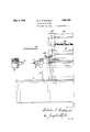
In the drawings Y y Figures 1-1a are longitudinal sectional views of the invention;
Figure 2 is a detail view showing the microscope and associated parts in front elevation;`
Figure 3 is a rear elevation of the base portion of Figure 2; y
F igure-4 is a side elevation of Figure' 3;
Figure 5 is an end elevation of the Ymeans for actuating thev measuring bar;
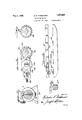
Figure 6 is a top plan view of Figure 2; y Figure 7 is a top plan view of one of the measuring disks;
Figure 8 is a top plan view ated or measuring bar;
' Figure 9 is a side elevation of Figure 8, and c Figure 10 is an enlarged detail view of the plug showing the lines of graduations for one'one-hundredth of an'inch thereon;
Figure 11 is a top plan view of Figure 12;
Figure 12 is a Vdetail view of the eyepiece o section of the microscope showing the micrometer and associated parts in front elevation;
Figure 13 is an end elevation showing the eyepiece and associated parts.
A In proceeding in accordance with the present invention a bed 1 is employed, on which is mounted a headstock 2. In Figure la, a tail stock 3 is shown which has a work engaging anvil or point 4. VA spindle 5 is mounted in the headstock and has a work engaging end 6 which confronts the anvil 4. The spindle 5 is movable longitudinally of the headstock, by means of a rotating wheel 7 having a handle'8 thereon. The wheel 7 is `connected to a threaded member 9 which ext-ends longitudinally within the spindle, the member 9 engaging the interior threads 'of a sleeve-10 which la-tteris connected to spindle 5 and to a graduated bar 11 by screws 50 12. yOther screws 1-3 secure the bar 11 to the yof the gradu- ,the spindle 5 against movement.
The plate 42 has a central Opening across which there is theusual microscope hair line 42 and is provided with a pin 43 the plate 42 being slidable with the pin 43 inthe eyepiece section of the microscope.
` A graduated disk 44 is rotatably and 're-y movably mounted on a stud 45 carried by the plate 38 and is provided With radially'extending pins 46 adapted to engage with the pin 43. y v
The pins 46 are of varying length to compensate for minute errors in. graduations appearing on the graduated bar.' lli;
Referring to Figures 8, 9 and 10,7the bar 11 is shown as provided With a series or" plugs or scale 47 is secured toben-151 and hasta readings of the range of one inch by tenthsV and the plug 472 is also imounted to, provide.y
readings to one one-hundredth of' an inch anglaise carries ai second series o graduations se spaced aste gineneadings of. one cne-thou Sandthcf-an inch@ 1, Y Y
Thev graduated disk 49 shewninFigure. 7 is adapted tof beV placed?V en,` the stud '45015 the p microscope t191-obtain, finall readings. i
The screw 33de employed;tedisconnect the disk 28`=romcthe Wormgear'30lor quick movement of the microscope: and the Wheeli32and its Worm 3l is used toA obtain fine adjjiistment of. thefmiscroscope: ...The screvv 19 disconnects tliediisk Z from the ,Wormgean; 14 for `Guick 'adjustment of the-spindle? 5- and-the Worm 17 its Wheel.,]i8.is.-or thev line adjustment and. corresponds. inactinn. to Wheel` 32..
The eyepiece structureshown ,inl Figures 1lt 12:and: 13.` for use when it is desirable tomake veryine: adJustments asrreadings 1n ten. thnusandths, 9001; In this' iornr ami-- crometer structure:l is adjnstabb7 secu-red. to the supporting plate 38"' andearriesthe stud 45"upon.w,hich thefdisk44 ismounted.v in such manner tliatthe disk.. 44 may be advanced A to bring the` pin useY to: the. desiredV point k40 by ,operating the. knob.. 5,6). of the. micrometer. rIPhe supporting plate. 38 liasthe, downwardly extendingpart 51 into which. the micrometer screw 52 i's screw/threaded, the disk carrying part 53 is slidablyvsecured to thefpa-rt 5l by tWjo pi`ns54 and 544g In' ,operation and referring., to lTi-g. l, it
will benoted thatthe spindle. 5.,.Which. moves the graduated bar Il unison therewith,.is at-the eXtreme rightofthe drawing- Now if yWe consider the Work engagingpart 4,8astfixed or the zero point,.theollovving steps are neeessary to obtain a space or distanceof 2.3645 between thefvvork engaging pa-rts 4 and 6.1; As the parts 4` and 6` are Widely separated in the .drawings ,.Fi'g'gl and 100 it is necessary that the part 6'bemoved` to contact with the part ,4 and/ait the Sametime the graduated bar ll is moved toward the left untill the partA 6 cont'actsWith ,the part 4 or thezero pointrwhereupon the? spindle 5,.,.Which carries the graduated bar is theny loekedagainst. movement. Thefdevice is now in position to. start' the setting of the same tozform an open space between the parts 4 andtf for theabove reading, Thedisk 44 is first placedonthe stud 45 ofthe microscope support 38 With the zero pin 0 in contact with the pin 43 of the movable part 42 Which carries the hair line 42', as shown in Fig. 6. The next step is to rotate the disk'44 to bring the pin 2 of the inches section in line with thepin- 43. to move the hair line, minus or pLus, astlie casevmay' be, depending upon setting of the line 2.0 on the bar 1l, whereupon the microscope ,is moved to the point'- Where the hair line-'424' coincides fwiththeOV'lineof the bar 11. series of graduations mounted so as to obtainV Y The dial 44 is noW turned so as to bring thepin Stof the tenths section into alignment With the. pin43which action further displ'aces the hair line 42 as above described. 'li'he spindle; -5- is then releasedY andwith` the bar Il- .is moved.- by revolving the handley 8 to the right; until stops number 8f eS the-tenths divisio1r47 on# the bar V1l ,coincides with the .hair line of the microscope..At thisfpoi'nt line andalockedi-n place, whereupon the' dial 49iisthen. turnedto bring the pin 4 'of-.the thousandths group in Contact Withfthe pi-n|43 thus adjusting; the microscope-hair Line..k The; mi-
crometer is adjusted tornumbierl Wliichgives the .0005' reading,i and spindle 5 With-the bar 11 is then released and the spindle and bar 1l adjusted until the fourth line of the .thousaindths. group. plug47 21 coincidesVV with hair line of the microscope, whereby themeasuringepoints :4 8 are separated for'measuring y2.8645fand; thenthespindllie 5 is finally locked.
The above coversthe setting of the machine toA a predetermined measurement but' Where there are a' number of pieces to be tested-as vvtoininusor plusathe.v spindle withi thework engaging end Gbecomes aLockediXedpoin-t and. the device described,in anA application filed; December 228,. 19.28,- No.:328,984is subs-ti,- tutedy fory the anvil4-whi-ch. will giveY a, read' ing ofpl'us or. minus or zero-or the device disclosed in. application ilfed. December 28, 1928, .No328,981.5,"may be. used ,inv place of the g anvil 4.
From; thezforegoingit will be-noted that parte 4 and 'being in contact, the` spindle 5 and bar 11; are locked that` position, and with the dial 44 in position, the number 2 pfin. is brought line. with pinA 43 which controls. theY position of the microscope hair line 424.. pin: number 2 may be zero, plus or minus depending, uponthe predetermined setting ,thehair -line ,2r on-the bar It, and
will aord such setting by reason of moving the microscope hair line 42. When the hair line is in absolute correction with the end 6 in zero position, the microscope is released and moved so that the hair line is absolutely in line with the line 2 of bar l1 and locked against all movement. When the dial 44 is turned to bring the pin 8 in the tenths section into line with pin 43, the microscope hair line 42 is moved to correct any discrepancy in the location of the 8 tenths line on the bar 11. Up to this point 4 and 6 are still in contact. The spindle 5 being released by the operation of the handle 8, the part 6 moves away from 4 until the hair line 8 tenths of the bar 11 coincides with the hair line of the microscope'and then the spindle 5 is locked, the two points 4 and 6 being separated by 2.8"; thus step by step the machine is adjusted.
Having thus described my invention what I claim as new and desire to secure by Letters Patent is :4 Y
l. In a measuring apparatus, a bed, a head stock and tail Vstock on the bed, spindles carried by the head stock and tail stock to engage the work therebetween, means to adjust the spindle of the head stock relative to the latter, a microscope carried by the head stock, means to adjustably move the microscope relative to the head stock, a graduated bar carried by the spindle of the head stock and disposed beneath the microscope, a slidable member carried by the microscope and having an opening rcgistrable with the microscope eye piece and provided with across hair, a pin on the member, means to tension the member, and a. rotatable dial carried by the microscope and having radial pins of predetermined lengths selectively engageable with the pin of said member to position the member to compensate for discrepancies o1 said graduated bar. Y
2. In a measuring apparatus, opposed movable work engaging members, a graduated bar, means to connect said bar to one of said members for mov-ement therewith, a microscope, means to adjustably mount the microscope over the bar a slidable member associated with the microscope and having an opening for registry with the microscopic eye piece and having a cross hair in the opening, means to tension the slidable member, a pin on said slidable member, and a graduated dial rotatably supported by said microscope and having radial pins of varying lengths associated with its graduations for selective engagement with the pin of the slidable member to position the cross hair.
3. In a measuring apparatus, opposed movable work engaging members, a graduated bar, means to connect said bar to one of said members for movement therewith, a microscope, means to adj ustably mount the microscope over said bar, a slidable member associated with the microscope having ani-opening for registry with the microscope eye piece 4.y f In a measuring apparatus, opposed movable work engaging means, graduated means actuated by one of the said work engaging means, al microscope, means to adjustably mount the microscope over said graduated means, slidable means associated with and movable relative to the eye piece of the microscope and having a cross hair for registry with the graduated means, and rotatable means having radial projections of predetermined lengths to selectively engageand position said slidable means and thereby the cross hair.
5. In a measuring apparatus, a movable work engaging element, a graduated bar having connection with said element for movement therewith, a microscope overlying the bar, means to adjust the microscope relative to the bar, a slidable means having an opening and having a cross hair there-across for registry with the microscope and the. graduated bar, means to mount the slidable means on the microscope, a rotary graduated dial mounted on the microscope and having abutments of varying lengths associated with its graduations to selectively engage the slidg able means and means to tension the slidable means.
6. In a measuring apparatus, a lmovable work engaging element, a graduatedbar having connection with said element for movement therewith, a microscope overlying the bar, means to adjust the microscope yrelative to the bar, a slidable member having an opening and having a cross hair, means to mount the slidable member on the microscope, a rotatable dial having projections of varying lengths asso-ciated therewith for selectively engaging the movable member, and a micrometer carried by the miscroscope to adjust the cross hair.
7. In a measuring apparatus, opposed movable work engaging means, graduated means carried by one of said work engaging means,
a miscroscope Jfor observation of said grad- 4 :,aamoss mmcroscopekfr. observatonvff said graduated emexms' "Qhawinggg'y a 1 cr0ss-ha1'-- carrying membergand-a rotatable member having projections: of predetermined. lengths; t0.ser1ecl ively engageyanlfposson -the cross-hair carryngmember and therebycompensatefor 'discrepancies of said graduatedxmeans. A
Ill-testimony -.Whe1reof I have signed my nameaV this! specication,
MAIJIW` K.; PARK-HURST.
kim
Priority Applications (1)
| Application Number | Priority Date | Filing Date | Title |
|---|---|---|---|
| US328986A US1857088A (en) | 1928-12-28 | 1928-12-28 | Measuring machine |
Applications Claiming Priority (1)
| Application Number | Priority Date | Filing Date | Title |
|---|---|---|---|
| US328986A US1857088A (en) | 1928-12-28 | 1928-12-28 | Measuring machine |
Publications (1)
| Publication Number | Publication Date |
|---|---|
| US1857088A true US1857088A (en) | 1932-05-03 |
Family
ID=23283342
Family Applications (1)
| Application Number | Title | Priority Date | Filing Date |
|---|---|---|---|
| US328986A Expired - Lifetime US1857088A (en) | 1928-12-28 | 1928-12-28 | Measuring machine |
Country Status (1)
| Country | Link |
|---|---|
| US (1) | US1857088A (en) |
Cited By (2)
| Publication number | Priority date | Publication date | Assignee | Title |
|---|---|---|---|---|
| US2580255A (en) * | 1945-02-12 | 1951-12-25 | Newall Eng | Distance gauge |
| US3217416A (en) * | 1962-07-06 | 1965-11-16 | Western Electric Co | Carriage displacement measuring apparatus |
-
1928
- 1928-12-28 US US328986A patent/US1857088A/en not_active Expired - Lifetime
Cited By (2)
| Publication number | Priority date | Publication date | Assignee | Title |
|---|---|---|---|---|
| US2580255A (en) * | 1945-02-12 | 1951-12-25 | Newall Eng | Distance gauge |
| US3217416A (en) * | 1962-07-06 | 1965-11-16 | Western Electric Co | Carriage displacement measuring apparatus |
Similar Documents
| Publication | Publication Date | Title |
|---|---|---|
| US2043625A (en) | Adjustment of the carriage of machine tools | |
| US2557876A (en) | Adjustable compensating tracer style unit | |
| US1857088A (en) | Measuring machine | |
| US2249904A (en) | Grinding gauge caliper frame | |
| US2348712A (en) | Gear testing machine | |
| JPS5861404A (en) | Tester for inspecting form of tooth surface and direction of tooth surface of involute gear of flat tooth or oblique tooth | |
| US1389381A (en) | Taper-gaging caliper | |
| US2200884A (en) | Positioning device for machine tool tables | |
| US1588963A (en) | Gear-testing apparatus | |
| US1836662A (en) | Cutter truing device | |
| US1329005A (en) | Protractor | |
| US2131973A (en) | Work positioning means | |
| US2060518A (en) | Machine for measuring gears and helical leads | |
| US2025215A (en) | Lead testing device | |
| US3006331A (en) | Apparatus for dressing grinding wheels and holding work pieces thereto | |
| US1528314A (en) | Machine for measuring, gauging, or the like | |
| US2268354A (en) | Adjustable pin gauge | |
| US2179211A (en) | Form grinding apparatus | |
| US2442453A (en) | Grinding wheel dressing tool | |
| US1324454A (en) | Edge-grinding machine | |
| US2623295A (en) | Gear checking apparatus | |
| US2583408A (en) | Sine-bar grinding wheel truing device | |
| US2511418A (en) | Gear finishing machine | |
| US2538311A (en) | Multiple check comparator gauge | |
| US2166020A (en) | Apparatus for dressing the grinding wheels used for gearing |