US1857086A - Means for preventing condensation in refrigerator walls - Google Patents
Means for preventing condensation in refrigerator walls Download PDFInfo
- Publication number
- US1857086A US1857086A US320630A US32063028A US1857086A US 1857086 A US1857086 A US 1857086A US 320630 A US320630 A US 320630A US 32063028 A US32063028 A US 32063028A US 1857086 A US1857086 A US 1857086A
- Authority
- US
- United States
- Prior art keywords
- space
- walls
- cold chamber
- cabinet
- tube
- Prior art date
- Legal status (The legal status is an assumption and is not a legal conclusion. Google has not performed a legal analysis and makes no representation as to the accuracy of the status listed.)
- Expired - Lifetime
Links
- 238000009833 condensation Methods 0.000 title description 6
- 230000005494 condensation Effects 0.000 title description 6
- 239000011810 insulating material Substances 0.000 description 22
- 238000001816 cooling Methods 0.000 description 11
- 238000009413 insulation Methods 0.000 description 11
- 238000005057 refrigeration Methods 0.000 description 8
- 239000007788 liquid Substances 0.000 description 7
- 239000003507 refrigerant Substances 0.000 description 4
- 238000010521 absorption reaction Methods 0.000 description 3
- 238000010276 construction Methods 0.000 description 3
- 239000007799 cork Substances 0.000 description 3
- 238000010438 heat treatment Methods 0.000 description 3
- 239000000463 material Substances 0.000 description 3
- 230000029058 respiratory gaseous exchange Effects 0.000 description 3
- 235000007173 Abies balsamea Nutrition 0.000 description 2
- 239000004857 Balsam Substances 0.000 description 2
- 244000018716 Impatiens biflora Species 0.000 description 2
- 239000002184 metal Substances 0.000 description 2
- 230000000630 rising effect Effects 0.000 description 2
- 239000002023 wood Substances 0.000 description 2
- 239000006096 absorbing agent Substances 0.000 description 1
- 238000009825 accumulation Methods 0.000 description 1
- 150000001875 compounds Chemical class 0.000 description 1
- 239000004020 conductor Substances 0.000 description 1
- 239000002826 coolant Substances 0.000 description 1
- 230000000694 effects Effects 0.000 description 1
- 230000008020 evaporation Effects 0.000 description 1
- 238000001704 evaporation Methods 0.000 description 1
- 230000002349 favourable effect Effects 0.000 description 1
- 239000012774 insulation material Substances 0.000 description 1
- 238000000034 method Methods 0.000 description 1
- 238000010422 painting Methods 0.000 description 1
- 239000011253 protective coating Substances 0.000 description 1
- 229920006395 saturated elastomer Polymers 0.000 description 1
- 238000007789 sealing Methods 0.000 description 1
- 230000002459 sustained effect Effects 0.000 description 1
- 238000010257 thawing Methods 0.000 description 1
- 230000008016 vaporization Effects 0.000 description 1
- 238000010792 warming Methods 0.000 description 1
Images
Classifications
-
- F—MECHANICAL ENGINEERING; LIGHTING; HEATING; WEAPONS; BLASTING
- F25—REFRIGERATION OR COOLING; COMBINED HEATING AND REFRIGERATION SYSTEMS; HEAT PUMP SYSTEMS; MANUFACTURE OR STORAGE OF ICE; LIQUEFACTION SOLIDIFICATION OF GASES
- F25D—REFRIGERATORS; COLD ROOMS; ICE-BOXES; COOLING OR FREEZING APPARATUS NOT OTHERWISE PROVIDED FOR
- F25D23/00—General constructional features
- F25D23/06—Walls
- F25D23/065—Details
- F25D23/068—Arrangements for circulating fluids through the insulating material
-
- F—MECHANICAL ENGINEERING; LIGHTING; HEATING; WEAPONS; BLASTING
- F25—REFRIGERATION OR COOLING; COMBINED HEATING AND REFRIGERATION SYSTEMS; HEAT PUMP SYSTEMS; MANUFACTURE OR STORAGE OF ICE; LIQUEFACTION SOLIDIFICATION OF GASES
- F25D—REFRIGERATORS; COLD ROOMS; ICE-BOXES; COOLING OR FREEZING APPARATUS NOT OTHERWISE PROVIDED FOR
- F25D21/00—Defrosting; Preventing frosting; Removing condensed or defrost water
- F25D21/04—Preventing the formation of frost or condensate
-
- Y—GENERAL TAGGING OF NEW TECHNOLOGICAL DEVELOPMENTS; GENERAL TAGGING OF CROSS-SECTIONAL TECHNOLOGIES SPANNING OVER SEVERAL SECTIONS OF THE IPC; TECHNICAL SUBJECTS COVERED BY FORMER USPC CROSS-REFERENCE ART COLLECTIONS [XRACs] AND DIGESTS
- Y10—TECHNICAL SUBJECTS COVERED BY FORMER USPC
- Y10S—TECHNICAL SUBJECTS COVERED BY FORMER USPC CROSS-REFERENCE ART COLLECTIONS [XRACs] AND DIGESTS
- Y10S220/00—Receptacles
- Y10S220/09—Receptacles insulating materials
Definitions
- This invention relates to means for preventing the condensation of moisture in the interior of the insulated walls of refrlgeration cabinets and it is applicable to all classes of refrigerators wherein the cold chamber is enclosed by double walls consisting of spacedapart inner and outer sheets or panels of suit: able material between which there is a filling of insulation such as ground cork, balsam' wood, or the like.
- the innor and outer sheets or panels of a double wall construction will be referred to as the inner and outer walls, and either may consist of a continuous shell, as will hereinafter appear.
- the socalled cold chamber is of a higher temperature during the heating and condensing period than it is during the period of evaporation and absorption; and in other types of mechanical refrigerators, the temperature of the cold chamber is higher during the defrosting operation than at other times, and furthermore it fluctuates considerably dueto the intermittent operation ofthe apparatus.
- the primary purpose of my invention is to provide a refrigerator cabinet enclosing the so-called cold chamber and constructed of double or spaced-apart inner and outer walls, the space between said walls containing suitable insulating material, and to incorporate in such cabinet apassageway leading from the exterior tothe interior of said space and passing in intimate heat exchanging relation to a cooling medium, such as the cold chamber, so that when the pressure differential between the outer air;and the insulation space is in favor of the outer air, the atmospheric air drawn ingby reason thereof through said passageway is lowered in temperature below the temperature of said space so that any moisture in the air -that.would otherwise be condensed upon reaching the space is actually removed from the air by condensation in the passageway.
- the invention is especially suited for refrigeration apparatus of the intermittent absorption type because of the fact that at regular mtervals in the operation of the apparatus, the temperature of the cold chamber or refrigeration compartment is raised above normal operating temperature for a brief pe riodwhile the relatively hot refrigerant condensate is collecting in the evaporator.
- the warmth of the-evaporator is communicated, to a limited degree at least, to the walls of the cold chamber or refrigeration compartment and this causes the air within the insulation space of the walls to expand and, as the cabinets have heretofore been constructed, a part of it to be expelled through the small cracks or holes that are practically unavoidable, and then during the subsequent cooling period, when the refrigerant in the evaporator.
- the cabinet of the refrigerator is desig* nated 1 andit is made up of a framework comprising a base 2, top 3, rear corner posts 4 and front corner posts 5.
- An insulated door 6 swings between the last mentioned corner posts and closes the cold chamber or refrigeration compartment 7 that is formed by the interior of what is, in effect, a onepiece sheet metal shell that constitutes the inner wall, of the cabinet and is designated 8. While this one-piece shell is in accordance with the better practice, the wall 8 might be made up of a number of separate panels, so far as my present invention is concerned.
- Applied to the corner posts 4 and 5 are sheets or panels of suitable material, such as metal, and they constitute the outer wall that is constitutes the subject matter of my co-pend-.
- thecooling period when the liquid refrigerant in the coolin vessel or evaporator 12 evaporates and a stracts heat from the air within the chamber or compartment ,7, lowering the temperature thereof which is more or less variation in the temperature of the cold chamber or refrigeration compartment.
- a cup-shaped screen 16 surrounds the last mentioned end of the breather tube and prevents. the same from beingv closed or obstructed by the insulating material 10.
- the tube is inclined downwardly and forwardly so that its lowest part is adjacent the front of the chamber or compartment 7 said lowest part constituting a sump, and a drip spout 17 is connected to the sump and dips into a receptacle 18 which provides a liquid seal for the spout.
- the receptacle 18 overflows into a pan 19 that is shown as supported by a shelf 20 sustained by and besaid pan serving also to catch any c0n'densatewhich may drip from the cooling unit.
- a shelf 20 sustained by and besaid pan serving also to catch any c0n'densatewhich may drip from the cooling unit.
- the insulated door 6 closes the open front of the cabinet 1 and the same is made up of a frame 26 to the inner and outer sides of which are applied, respectively, the inner wall or panel 28 and the outer wall orpanel 29.
- a breather tube 32 whose body portion is located on the inner side of the wall 28 where it will be inside the cold chamber when the door is shut, and the upper endof the tube is extended through an aperture in said wall and opens into the insulation space, a screen 33 serving to space the insulation-material from the open end of the tube.
- the opposite end of the tube is shown as extended through apertures in the inner and outer walls28 and 29 so as to be open to the atmosphere; and it is, of course, understood that the apertures in the walls through which the ends of the tube pass aresealed against the ingress and egress of air.
- the outwardly extended lower end of the breather tube 32 is preferably inclined upwardly so as to pro vide a low part or sump 35 to which will gravitate any moisture condensed from. the atmospheric air as the latter passes upwardly through the tube in intimate heat exchang ing relation to the cold chamber of the' refrigerator.
- the sump 35. is drained through a spout 36 into a receptacle 37 which is-so related to thespout as to provide a liquid seal therefor, and the receptacle overflows into a receiver38 that is shown as removably supported by the door so that it may be conveniently emptied as occasion requlres.
- a characteristic of the breathing action of insulated refrigerator walls that is favorable to the present invention is that the exhalation occurs during the time the temperature of the cold chamber is rising and the inhalation takes placeafter the temperature of the cold chamber has fallen enough to lower the-temperature in the insulation space of the walls. Consequently, when the air is being drawn in through the breather tube the temperature of the walls of said tube-will be sufliciently below that of the insulation space to insure condensation of all moisture in the existing in said space, said passageway being arranged to drain any moisture condense therein away from said space.
- a refrigerator comprising a cabinet having spaced-apart inner and outer walls and enclosing a cold chamber, the space between said walls containing insulating material, the cabinet incorporating a passagelation to the cold chamber, the samebeing so arranged as to drain any moisture condensed therein away from said space.
- a refrigerator comprising a cabinet tweensaid walls containing insulating material, the cabinet incorporating a passagea-nd passing-in-intimate heat exchanging relation to the cold chamber, the same involv- 'ing a sumpwherein any moisture that is con densed in the passageway will collect.
- a refrigerator comprising a cabinet and enclosing a cold chamber, the space between said walls containing insulating material, the cabinet incorporating a passageway leading from its exterior to said space and passing in intimate heat exchanging relationto the cold chamber, the same involving a [sump vwherein an'y moisture that is condensed in the passageway will collect, and means permitting the egress of condensate way-leading from its exterior tosaid space and passing in intimate heat exchanging rehaving spaced-apart inner and outer walls and enclosing a cold chamber, the space be- .way leadingfrom its exterior to said space having spaced-apart inner and outer walls from the sump and preventing the ingress of air thereto from the cold chamber. 5.
- a refrigerator comprising a cab net I having spaced-apart inner and outer walls and enclosing a coldv chamber, the space between said Walls containing insulating material, a conduit opening at one end ext-eriortween said walls containing insulating ma terial, a breather tube opening at one end exteriorly of the cabinet and at its opposite end into said space and having a part located within said cold chamber, the tube being .inclined to drainany moisture that is condensed within it away from said space.
- a refrigerator comprising acabinet having a spaced-apart inner and outer walls and enclosing a cold chamber, the space between said walls containing insulating material, a breather tube opening at one end exteriorly of the cabinet and'at its opposite end into said space and having a part located within said cold chamber, said part incorporating a sump to which any moisture that is condensed within the tube drains, said sump being provided with an outlet.
- a refrigerator comprising a cabinet having spaced-apart inner and outer walls and enclosing a cold chamber,- the space between said walls containing insulating material, a breather tube opening at one end exteriorly' of the cabinet and at its ,opposite end into said space and having a part located within said cold chamber, said part incorporating a sump to which any moisture that is condensed within the tube drains, said sump being provided with an outlet, and a liquid seal for said outlet.
- a cabinet having spaced-apart inner and outer was and enclosing a cold chamber, insulating material in the space between said walls, a cooling unit within said chamber, a breather consisting of two tubular branches that are communicatively connected together adjacent their inner ends and are disposed in intimate heat exchanging relation to the cooling unit, the
- the breather having a sump for. the accumulation of condensate, and a drain for said sump.
- a cabinet having spaced-apart inner and outer walls and enclosing a cold chamber, insulating material in the space between said walls, a cooling unit within the cold chamber, a U- haped breath-j er tube disposed below said cooling unit and open into the atmosphere and its opposite end extended through the inner wall of the cabinet so as to open into the space contain ing the insulating material, the tube being inclined downwardly and inwardly and having draining means at its low point.
- a cabinet having spaced-apart inner and outer walls and enclosing a cold chamber, insulating material in the space between said walls, a cooling unit within the cold chamber, a U- haped breather tube disposed below said cooling unit and having one of its ends extending through the inner and outer walls of the cabinet so as to open into the atmosphere and its opposite cabinet so as to open into the spaceconta-ining end extended through the inner wall of the the insulating material, the tube being inclined downwardly and inwardly and having.
- a'drainopening at its low point, and a receptacle supported in receiving relation to said drain opening and providing a liquid seal therefor.
- a cabinet enclosing the cold chamber and having a door opening, a door for closing said opening and comprising spaced-apart inner and outer walls, the space between said walls containing insulating material, the door incorporating a passageway leading from its exterior to said space and passing in intimate heat exchanging relation to the cold chamber, the passageway involving a sump wherein any moisture that is condensed in the passageway will col- 'lect, and means for draining thesump.
- a cabinet enclosing the cold chamber and having a door opening, a door for closing said opening and comprising spaced-apart inner and outer walls, the space between said walls containing insulating material, the door incorporating a passageway leading from its exterior to said space and passing in intimate heat exchanging relation to the cold chamber, the said passageway involving a sump wherein any moisture that is condensed in the passageway will collect, and a liquid seal through which said sump is drained.
- a cabinet enclosing the cold chamber and having a door opening, a door for closing said opening and comprising spaced-apart inner and outer walls,
- a door for closing said opening and com rising spaced-apart inner and outer walls, insulating material in 'the space between said Walls, a breather tube having its body portion disposed inwardly of the inner wall and having one of its ends extended through the inner and outer walls so as to be open to the atmosphere, the opposite end of the-tube openinginto the space between said walls, the tube being so formed as to provide a sump, a drain spout for said sump which discharges on the inner side of the door, and a vessel into which said spout drains.
- a cabinet enclosing a cold chamber and having a door opening, a door for closing said opening and comprising spaced-apart inner and outer walls, insulating material in the space between said walls, a. breather tube-having its body por tion disposed inwardly of the inner wall and having one of its ends extended through the inner and outer walls so as atmosphere, opening into the space betweensaid walls, the tube being so formed as to provide a sump, a drain spout for said sump whichdischarges on the inner side of the door, a recepto be open to the tacle so disposedwith respect to said spout as to provide a liquid seal therefor, and a reinto DCver removably supported by the door which said receptacle overflows.
- a breather tube having its body'por-.
Landscapes
- Engineering & Computer Science (AREA)
- Chemical & Material Sciences (AREA)
- Combustion & Propulsion (AREA)
- Physics & Mathematics (AREA)
- Mechanical Engineering (AREA)
- Thermal Sciences (AREA)
- General Engineering & Computer Science (AREA)
- Cold Air Circulating Systems And Constructional Details In Refrigerators (AREA)
Description
May 3, 1932. D. F. KEITH 1,857,086
MEANS FOR PREVENTING QONDENSATION IN REFRIGERATOR WALLS Filed Nov. 20. 1928 s SheetS -Sheet 2 .J Y L 30 a M 5 K J J -28 ,W a b R /0 a g moz P QMQRM May 3, 1932. D. F. KEITH 1,357,036
MEAP IS FOR PREVENTING CONDENSATION IN REFRIGERATOR WALLS Filed Nov. 20, 1928 3 Sheets-Sheet 3 -caused also by changesin barometer pressure,
the atmospheric air is Patented May 3, 19 32 UNITED STATES PATENT. OFFICE.
DAVID E. KEITH, or crfivnrmn HEIGHTS, oHIo, AssIeNon 'ro rmrnc'rrox STOVE comrm, or CLEVELAND, onto, a conronarron or 01:10
MEANS FOR PREVENTING COHDENSATION IN REFRIGERATOR .WALLS Applicatlonfiled November 20, 1928. Serial no. 920330.
This invention relates to means for preventing the condensation of moisture in the interior of the insulated walls of refrlgeration cabinets and it is applicable to all classes of refrigerators wherein the cold chamber is enclosed by double walls consisting of spacedapart inner and outer sheets or panels of suit: able material between which there is a filling of insulation such as ground cork, balsam' wood, or the like.
For the purpose of this descriptiomthe innor and outer sheets or panels of a double wall construction will be referred to as the inner and outer walls, and either may consist of a continuous shell, as will hereinafter appear.
a fresh supply of ice isplaced within the ice compartment; in refrigeration apparatus of the intermittent absorption type, the socalled cold chamber is of a higher temperature during the heating and condensing period than it is during the period of evaporation and absorption; and in other types of mechanical refrigerators, the temperature of the cold chamber is higher during the defrosting operation than at other times, and furthermore it fluctuates considerably dueto the intermittent operation ofthe apparatus.
In the construction of double wall refrigerator cabinets, it is practically impossible to make the space between the inner and outer walls air tight, and as a consequence of this, when the temperature within the cold cham-' ber rises, the air within the space between the inner and outer walls expands and some the air within the walls contracts-and draws Obviously, this breathin atmospheric air.
ing action of the insulated walls may changes in outside temperature, etc. Since practically always In practically all types of refrigerators, there is a pronounced fluctuation of the tem more or less humid, the moisture which it contains 1s condensed when it comes within the chilling influence of the inner wall that.
separates the insulation space from the cold chamber and the insulation within said space absorbs the moisture untilfinally it becomes ,so saturated that it has little insulting value.
In fact, when it becomes wet it is a conductor of heat between the inner and outer wall panels.
Attempts have been made to overcome this difficulty by hermetically sealing the insulating material. Cork, for example, has been thoroughly coated with a composition ofasphalt, as by dippin or painting the cork with the compound. (Stber kinds of insulation have been wrapped in Waxed paper. Both of these methods of moisture proofing the insulation are costly and require a great deal of care in order to make certain that every openmg is sealed, for the-smallest opening in the protective coating will defeat the purpose thereof. By providing means for preventing .the condensation of moisture in the interior of the insulated walls of refrigerators,-much cheaper insulating materials may be used with highly satisfactory .results.
The primary purpose of my invention is to provide a refrigerator cabinet enclosing the so-called cold chamber and constructed of double or spaced-apart inner and outer walls, the space between said walls containing suitable insulating material, and to incorporate in such cabinet apassageway leading from the exterior tothe interior of said space and passing in intimate heat exchanging relation to a cooling medium, such as the cold chamber, so that when the pressure differential between the outer air;and the insulation space is in favor of the outer air, the atmospheric air drawn ingby reason thereof through said passageway is lowered in temperature below the temperature of said space so that any moisture in the air -that.would otherwise be condensed upon reaching the space is actually removed from the air by condensation in the passageway.
Other objects of the invention are to provide means of the aforesaid character that is simple, relatively inexpensive, highly efii cient, that requires no attention, and will not get out of order.
The invention is especially suited for refrigeration apparatus of the intermittent absorption type because of the fact that at regular mtervals in the operation of the apparatus, the temperature of the cold chamber or refrigeration compartment is raised above normal operating temperature for a brief pe riodwhile the relatively hot refrigerant condensate is collecting in the evaporator. Each time this occurs, the warmth of the-evaporator is communicated, to a limited degree at least, to the walls of the cold chamber or refrigeration compartment and this causes the air within the insulation space of the walls to expand and, as the cabinets have heretofore been constructed, a part of it to be expelled through the small cracks or holes that are practically unavoidable, and then during the subsequent cooling period, when the refrigerant in the evaporator. is vaporizing and being distilled over into the generator absorber the temperature of the cold chamber or refrigeration compartment falls as does also the temperature of the air within the insulated walls causing said air to-contract and draw in atmospheric air. This breathing action occurs with every change of temperature of the cold chamber.
Because of its peculiar adaptabilityito the class of apparatus just described, Ihave illustrated my invention in connection therewith in theaccompanying drawings wherein Fig. 1
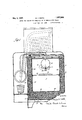
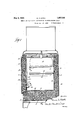
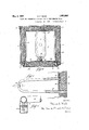
a5 is a sectional front elevation of refrigeration apparatus incorporating my present improvements, all parts excepting the cabinet being shown in elevation; Fig. 2 on-a somewhat larger scale, is a vertical section through the cabinet from front to rear; Fig. 3 is a sectional plan, the plane of section-being immediately below the top of the cabinet; Fig. 4 is a horizontal section through the breather tube and the adjacent portion of the cabinet wall, the same being on a Scale considerably enlarged over thatof the previous views, and Fig. 5 is a sectional detail on the line 55 of Fig. 4.
The cabinet of the refrigerator is desig* nated 1 andit is made up of a framework comprising a base 2, top 3, rear corner posts 4 and front corner posts 5. An insulated door 6 swings between the last mentioned corner posts and closes the cold chamber or refrigeration compartment 7 that is formed by the interior of what is, in effect, a onepiece sheet metal shell that constitutes the inner wall, of the cabinet and is designated 8. While this one-piece shell is in accordance with the better practice, the wall 8 might be made up of a number of separate panels, so far as my present invention is concerned. Applied to the corner posts 4 and 5 are sheets or panels of suitable material, such as metal, and they constitute the outer wall that is constitutes the subject matter of my co-pend-.
ing application Serial No. 242,574, filed December 27, 1927, and for a detailed description of the construction and operation of the apparatusreference may be had to the said case. It is suflicient for the present purpose to explain that during what is known as the heating period of each cycle of operation, relatively hot refrigerant condensate collects within the cooling unit or evaporator 12 and warms the same which results in a'noticeable rise in temperature of the air in the chamber or compartment 7 and, through the conductivity of the wall 8, in a warming up of the air within the space between said wall and the outer wall 9.
Following the heating period is what is known as thecooling period when the liquid refrigerant in the coolin vessel or evaporator 12 evaporates and a stracts heat from the air within the chamber or compartment ,7, lowering the temperature thereof which is more or less variation in the temperature of the cold chamber or refrigeration compartment.
In the present embodiment of my invention,
I employ a U-shaped breather tube 15 that.
is disposed immediately below the cooling unit or evaporator 12 and which has one of its ends extended through the rear sections of the inner and outer walls 8 and 9, and its other end projected through the wall 8 so as to open into the space between said walls. A cup-shaped screen 16 surrounds the last mentioned end of the breather tube and prevents. the same from beingv closed or obstructed by the insulating material 10. The tube is inclined downwardly and forwardly so that its lowest part is adjacent the front of the chamber or compartment 7 said lowest part constituting a sump, and a drip spout 17 is connected to the sump and dips into a receptacle 18 which provides a liquid seal for the spout. The receptacle 18 overflows into a pan 19 that is shown as supported by a shelf 20 sustained by and besaid pan serving also to catch any c0n'densatewhich may drip from the cooling unit. It will be readily understood from the foregoing description that when the breathing action occurs within the space between the innor and outer walls 8 and 9, air is alternately expelled and inhaled through the breather tube 15, and such moisture in the air that is drawn in through said tube as would otherwise be condensed in the space of the wall iscondensed when subjected to the cooling influence of the unit or evaporator 12 and drains to the lowest point of the breather tube from which it escapes through the drip spout 17 into the receptacle 18, said receptacle, in turn, overflowing into the pan 19, as .above explained. Thus it Willbe seen that no moisture can condense from the air that finds its way to the space between the walls 8 and 9 of the cabinet because the air has previously been subjected to a temperature lower than that which exists in said space, and consequently the insulating material 10 never becomes moist, but remains dry and retains its maximum insulating value indefinitely;
The insulated door 6 closes the open front of the cabinet 1 and the same is made up of a frame 26 to the inner and outer sides of which are applied, respectively, the inner wall or panel 28 and the outer wall orpanel 29. The space between said walls-isfilled with insulating material 30, which, as in the case of the insulated walls of the cabinet, may be balsam wood.
To protect the insulation of the door from moisture I employ a breather tube 32 whose body portion is located on the inner side of the wall 28 where it will be inside the cold chamber when the door is shut, and the upper endof the tube is extended through an aperture in said wall and opens into the insulation space, a screen 33 serving to space the insulation-material from the open end of the tube. The opposite end of the tube is shown as extended through apertures in the inner and outer walls28 and 29 so as to be open to the atmosphere; and it is, of course, understood that the apertures in the walls through which the ends of the tube pass aresealed against the ingress and egress of air. The outwardly extended lower end of the breather tube 32 is preferably inclined upwardly so as to pro vide a low part or sump 35 to which will gravitate any moisture condensed from. the atmospheric air as the latter passes upwardly through the tube in intimate heat exchang ing relation to the cold chamber of the' refrigerator. The sump 35. is drained through a spout 36 into a receptacle 37 which is-so related to thespout as to provide a liquid seal therefor, and the receptacle overflows into a receiver38 that is shown as removably supported by the door so that it may be conveniently emptied as occasion requlres.
The manner in which this breather tube functions will be obvious from the above descriptlon of the operation of the breather tube A characteristic of the breathing action of insulated refrigerator walls that is favorable to the present invention is that the exhalation occurs during the time the temperature of the cold chamber is rising and the inhalation takes placeafter the temperature of the cold chamber has fallen enough to lower the-temperature in the insulation space of the walls. Consequently, when the air is being drawn in through the breather tube the temperature of the walls of said tube-will be sufliciently below that of the insulation space to insure condensation of all moisture in the existing in said space, said passageway being arranged to drain any moisture condense therein away from said space.
y 2. A refrigerator comprising a cabinet having spaced-apart inner and outer walls and enclosing a cold chamber, the space between said walls containing insulating material, the cabinet incorporating a passagelation to the cold chamber, the samebeing so arranged as to drain any moisture condensed therein away from said space.
3. A refrigerator comprising a cabinet tweensaid walls containing insulating material, the cabinet incorporating a passagea-nd passing-in-intimate heat exchanging relation to the cold chamber, the same involv- 'ing a sumpwherein any moisture that is con densed in the passageway will collect.
4; A refrigerator comprising a cabinet and enclosing a cold chamber, the space between said walls containing insulating material, the cabinet incorporating a passageway leading from its exterior to said space and passing in intimate heat exchanging relationto the cold chamber, the same involving a [sump vwherein an'y moisture that is condensed in the passageway will collect, and means permitting the egress of condensate way-leading from its exterior tosaid space and passing in intimate heat exchanging rehaving spaced-apart inner and outer walls and enclosing a cold chamber, the space be- .way leadingfrom its exterior to said space having spaced-apart inner and outer walls from the sump and preventing the ingress of air thereto from the cold chamber. 5. A refrigerator comprising a cab net I having spaced-apart inner and outer walls and enclosing a coldv chamber, the space between said Walls containing insulating material, a conduit opening at one end ext-eriortween said walls containing insulating ma terial, a breather tube opening at one end exteriorly of the cabinet and at its opposite end into said space and having a part located within said cold chamber, the tube being .inclined to drainany moisture that is condensed within it away from said space.
7. A refrigerator comprisingacabinet having a spaced-apart inner and outer walls and enclosing a cold chamber, the space between said walls containing insulating material, a breather tube opening at one end exteriorly of the cabinet and'at its opposite end into said space and having a part located within said cold chamber, said part incorporating a sump to which any moisture that is condensed within the tube drains, said sump being provided with an outlet.
8. A refrigerator comprising a cabinet having spaced-apart inner and outer walls and enclosing a cold chamber,- the space between said walls containing insulating material, a breather tube opening at one end exteriorly' of the cabinet and at its ,opposite end into said space and having a part located within said cold chamber, said part incorporating a sump to which any moisture that is condensed within the tube drains, said sump being provided with an outlet, and a liquid seal for said outlet.
9. In a refrigerator, a cabinet having spaced-apart inner and outer was and enclosing a cold chamber, insulating material in the space between said walls, a cooling unit within said chamber, a breather consisting of two tubular branches that are communicatively connected together adjacent their inner ends and are disposed in intimate heat exchanging relation to the cooling unit, the
outer end of one of said branches extending through the inner and outer walls of the cabinet so as to open into the atmosphere while the corresponding end of the other tube enters the space between said walls, the breather having a sump for. the accumulation of condensate, and a drain for said sump.
10. In 'a refrigerator, a cabinet having spaced-apart inner and outer walls and enclosing a cold chamber, insulating material in the space between said walls, a cooling unit within the cold chamber, a U- haped breath-j er tube disposed below said cooling unit and open into the atmosphere and its opposite end extended through the inner wall of the cabinet so as to open into the space contain ing the insulating material, the tube being inclined downwardly and inwardly and having draining means at its low point.
11. In a refrigerator, a cabinet having spaced-apart inner and outer walls and enclosing a cold chamber, insulating material in the space between said walls, a cooling unit within the cold chamber, a U- haped breather tube disposed below said cooling unit and having one of its ends extending through the inner and outer walls of the cabinet so as to open into the atmosphere and its opposite cabinet so as to open into the spaceconta-ining end extended through the inner wall of the the insulating material, the tube being inclined downwardly and inwardly and having.
a'drainopening at its low point, and a receptacle supported in receiving relation to said drain opening and providing a liquid seal therefor.
12. In a refrigerator, a cabinet enclosing the cold chamber and having a door opensulating material, the door incorporating a passageway leading from its exterior to said space and passing in heat exchanging relation to the cold chamber, the same being so arranged as to drain any moisture condensed therein away from said space.
13. In a refrigerator, a cabinet enclosing the cold chamber and having a door opening, a door for closing said opening and comprising spaced-apart inner and outer walls, the space between said walls containing insulating material, the door incorporating a passageway leading from its exterior to said space and passing in intimate heat exchanging relation to the cold chamber, the passageway involving a sump wherein any moisture that is condensed in the passageway will col- 'lect, and means for draining thesump.
14. In a refrigerator, a cabinet enclosing the cold chamber and having a door opening, a door for closing said opening and comprising spaced-apart inner and outer walls, the space between said walls containing insulating material, the door incorporating a passageway leading from its exterior to said space and passing in intimate heat exchanging relation to the cold chamber, the said passageway involving a sump wherein any moisture that is condensed in the passageway will collect, and a liquid seal through which said sump is drained.
15.. In a refrigerator, a cabinet enclosing the cold chamber and having a door opening, a door for closing said opening and comprising spaced-apart inner and outer walls,
insulating material in the space-between said walls tion disposed inwardly of the inner wall and having one of its ends extending through both inner and outer walls so as to be open to the atmosphere, the other end of said tube V opening into the space between the walls, the
tube being so arranged as to drain any moisture condensed therein away from said space.
16. In a refrigerator, a cabinet enclosing a cold chamber and having a door opening,
a door for closing said opening and com rising spaced-apart inner and outer walls, insulating material in 'the space between said Walls, a breather tube having its body portion disposed inwardly of the inner wall and having one of its ends extended through the inner and outer walls so as to be open to the atmosphere, the opposite end of the-tube openinginto the space between said walls, the tube being so formed as to provide a sump, a drain spout for said sump which discharges on the inner side of the door, and a vessel into which said spout drains. 1
' 17, In a refrigerator, a cabinet enclosing a cold chamber and having a door opening, a door for closing said opening and comprising spaced-apart inner and outer walls, insulating material in the space between said walls, a. breather tube-having its body por tion disposed inwardly of the inner wall and having one of its ends extended through the inner and outer walls so as atmosphere, opening into the space betweensaid walls, the tube being so formed as to provide a sump, a drain spout for said sump whichdischarges on the inner side of the door, a recepto be open to the tacle so disposedwith respect to said spout as to provide a liquid seal therefor, and a reinto ceiver removably supported by the door which said receptacle overflows.
In testimony whereof, I hereunto afiix my signature.
DAVID F. KEITH.
a breather tube having its body'por-.
the opposite end of the tube
Priority Applications (1)
| Application Number | Priority Date | Filing Date | Title |
|---|---|---|---|
| US320630A US1857086A (en) | 1928-11-20 | 1928-11-20 | Means for preventing condensation in refrigerator walls |
Applications Claiming Priority (1)
| Application Number | Priority Date | Filing Date | Title |
|---|---|---|---|
| US320630A US1857086A (en) | 1928-11-20 | 1928-11-20 | Means for preventing condensation in refrigerator walls |
Publications (1)
| Publication Number | Publication Date |
|---|---|
| US1857086A true US1857086A (en) | 1932-05-03 |
Family
ID=23247251
Family Applications (1)
| Application Number | Title | Priority Date | Filing Date |
|---|---|---|---|
| US320630A Expired - Lifetime US1857086A (en) | 1928-11-20 | 1928-11-20 | Means for preventing condensation in refrigerator walls |
Country Status (1)
| Country | Link |
|---|---|
| US (1) | US1857086A (en) |
Cited By (3)
| Publication number | Priority date | Publication date | Assignee | Title |
|---|---|---|---|---|
| US2454715A (en) * | 1946-03-08 | 1948-11-23 | Int Harvester Co | Device for preventing excessive condensation in the insulating space of refrigerators |
| US2604760A (en) * | 1950-04-29 | 1952-07-29 | Gen Electric | Moisture collecting and removing arrangement |
| US2754662A (en) * | 1954-03-24 | 1956-07-17 | Nash Kelvinator Corp | Refrigerating apparatus with moisture control means |
-
1928
- 1928-11-20 US US320630A patent/US1857086A/en not_active Expired - Lifetime
Cited By (3)
| Publication number | Priority date | Publication date | Assignee | Title |
|---|---|---|---|---|
| US2454715A (en) * | 1946-03-08 | 1948-11-23 | Int Harvester Co | Device for preventing excessive condensation in the insulating space of refrigerators |
| US2604760A (en) * | 1950-04-29 | 1952-07-29 | Gen Electric | Moisture collecting and removing arrangement |
| US2754662A (en) * | 1954-03-24 | 1956-07-17 | Nash Kelvinator Corp | Refrigerating apparatus with moisture control means |
Similar Documents
| Publication | Publication Date | Title |
|---|---|---|
| US4163373A (en) | Device for extracting moisture from a space | |
| CH635190A5 (en) | METHOD FOR REFRIGERATED STORAGE AND KEEPING FRESH PRODUCTS, AND COOLING FURNITURE FOR CARRYING OUT THE METHOD. | |
| US2250612A (en) | Refrigerating apparatus | |
| US2292032A (en) | Refrigerator cabinet | |
| US2341872A (en) | Household refrigerator with distilled water dispenser | |
| US1857086A (en) | Means for preventing condensation in refrigerator walls | |
| US2319522A (en) | Refrigerating apparatus | |
| US2304411A (en) | Refrigerating apparatus | |
| US2209431A (en) | Humidifier for mechanical refrigerators | |
| US2269205A (en) | Air cooling apparatus | |
| US2485115A (en) | Refrigerating apparatus having condensate collecting means | |
| US3213639A (en) | Automatic humidity control for vegetable and fruit storage | |
| US2634592A (en) | Vacuum vaporization-condensation cooling system | |
| KR101886578B1 (en) | A Showcase | |
| US2211713A (en) | Refrigerator | |
| US2149990A (en) | Humidity control for refrigerated spaces | |
| US1900580A (en) | Ventilated refrigerator | |
| US2552345A (en) | Refrigerating apparatus | |
| US1649732A (en) | Method and means of dry storage | |
| US2317775A (en) | Refrigeration apparatus | |
| US1537601A (en) | Electric household refrigerator | |
| US2306480A (en) | Refrigerator, air cooler, and the like | |
| US1768599A (en) | Refrigerating apparatus | |
| US2260275A (en) | Air conditioning apparatus | |
| US2212710A (en) | Refrigerator |