US1857078A - Refrigerating system - Google Patents
Refrigerating system Download PDFInfo
- Publication number
- US1857078A US1857078A US418932A US41893230A US1857078A US 1857078 A US1857078 A US 1857078A US 418932 A US418932 A US 418932A US 41893230 A US41893230 A US 41893230A US 1857078 A US1857078 A US 1857078A
- Authority
- US
- United States
- Prior art keywords
- race
- tubes
- liquid
- headers
- unit
- Prior art date
- Legal status (The legal status is an assumption and is not a legal conclusion. Google has not performed a legal analysis and makes no representation as to the accuracy of the status listed.)
- Expired - Lifetime
Links
- 239000007788 liquid Substances 0.000 description 17
- 238000001704 evaporation Methods 0.000 description 13
- 239000012530 fluid Substances 0.000 description 8
- 238000001816 cooling Methods 0.000 description 6
- 239000003507 refrigerant Substances 0.000 description 6
- 239000007789 gas Substances 0.000 description 4
- 239000012267 brine Substances 0.000 description 3
- 238000005192 partition Methods 0.000 description 3
- HPALAKNZSZLMCH-UHFFFAOYSA-M sodium;chloride;hydrate Chemical compound O.[Na+].[Cl-] HPALAKNZSZLMCH-UHFFFAOYSA-M 0.000 description 3
- QGZKDVFQNNGYKY-UHFFFAOYSA-N Ammonia Chemical compound N QGZKDVFQNNGYKY-UHFFFAOYSA-N 0.000 description 2
- CURLTUGMZLYLDI-UHFFFAOYSA-N Carbon dioxide Chemical compound O=C=O CURLTUGMZLYLDI-UHFFFAOYSA-N 0.000 description 2
- RAHZWNYVWXNFOC-UHFFFAOYSA-N Sulphur dioxide Chemical compound O=S=O RAHZWNYVWXNFOC-UHFFFAOYSA-N 0.000 description 2
- 239000007787 solid Substances 0.000 description 2
- 241000382509 Vania Species 0.000 description 1
- 229910021529 ammonia Inorganic materials 0.000 description 1
- 239000001569 carbon dioxide Substances 0.000 description 1
- 229910002092 carbon dioxide Inorganic materials 0.000 description 1
- 238000010276 construction Methods 0.000 description 1
- 239000000110 cooling liquid Substances 0.000 description 1
- 238000005057 refrigeration Methods 0.000 description 1
- 239000004291 sulphur dioxide Substances 0.000 description 1
- 235000010269 sulphur dioxide Nutrition 0.000 description 1
- XLYOFNOQVPJJNP-UHFFFAOYSA-N water Substances O XLYOFNOQVPJJNP-UHFFFAOYSA-N 0.000 description 1
Images
Classifications
-
- F—MECHANICAL ENGINEERING; LIGHTING; HEATING; WEAPONS; BLASTING
- F25—REFRIGERATION OR COOLING; COMBINED HEATING AND REFRIGERATION SYSTEMS; HEAT PUMP SYSTEMS; MANUFACTURE OR STORAGE OF ICE; LIQUEFACTION SOLIDIFICATION OF GASES
- F25B—REFRIGERATION MACHINES, PLANTS OR SYSTEMS; COMBINED HEATING AND REFRIGERATION SYSTEMS; HEAT PUMP SYSTEMS
- F25B39/00—Evaporators; Condensers
- F25B39/02—Evaporators
Definitions
- This invention relates to the art of refrigeration and is concerned primarily with the cooling of a fluid by circulating it over a refrigerant evaporator.
- J mong the objects of the invention is to provide a new and improved type of evaporating unit which will contribute to a more free circulation of the refrigerating fluid such as carbon dioxide, ammonia, sulphur dioxide, etc. and in which the'relative proportions of length, transverse area, and surface of the refrigerant paths are such as to permit contact of liquid refrigerant with the greater portion of the evaporating surface without carrying liquid refrigerant in objectionable amounts out of the evaporator.
- the refrigerating fluid such as carbon dioxide, ammonia, sulphur dioxide, etc.
- Another object of the invention is to provide a suitable channel hereinafter called race to permit rapid circulation of the fluid to be cooled over the evaporating unit.
- Figure 1 is a vertical section evaporating unit and race
- Figure 2 is a plan view showing a portion of the evaporating coils
- Figure 3 is an end View of unit and race as applied toan ice making tank and shows a portion of the chamber in which the ice cans are mounted,
- Figure 4 is an enlarged detail showing the nesting of evaporating coils
- Figure 5 is a diagrammatic plan view of the race in a tank for cooling liquid such as brine in an ice making tank, water, oil, etc.
- numeral 10 indicates a tank having a partition .11 running either lengthwise as shown in Figure 5 or crosswise to provide a chamber 12 in which ice cans 13 may be placed or which may act as a liquid storage space and a race 14 in which an evapcrating unit 15 may be placed.
- a pump 16 of any suitable construction may be provided for circulating liquid through the race 14 to bring it into contact with the evaporator 15 and to circulate it through the brine chamber 12.
- partition 11 instead of one partition 11 together with tank side 10 forming the sides of the race,
- the evaporator unit 15 will now'be described. This consists of a pair of upper headers 17 and 18 and lower headers 19 and 20, the latter being connected with a source of liquid refrigerant in a receiver not shown and the upperheaders being connected to the may be run through the to form the race.
- the ;upper headers are" connected by transverse pipes 21 and the lower headers by similar transverse pipes 22.
- Bowed tubes 23 are connected to the upper and lower transverse pipes 21and 22 and these tubes are bent so as to nest one within the other, being here shown as bent into W-shaped pipes. These pipesmay andpreferably' are bent near their ends as shown at 24' as they enter 22. The purpose of this is to simplify the problem of securing these tubes to the transverse pipes.
- the tubes 22- are staggered thus entering alternate the transverse pipesx21' and transverse pipes So as to provide sufiicient space'between adjacent tubes '23 to permit attaching to transverse pipes 21 and 22 and still get very c ose nesting of tubes in the unit. If the desired spacing of tubes in the unit is wider, the tubes need not be staggered.
- the headers 17, 18, 19 and 20 may be supported by a suitable frame work constituting supports 25 andbraces 26 arranged in any convenient form and of sufiicient strength to support tubes of the necessary size.
- the coil unit 15 therefore may be readily removed from the brine tank and replaced by'additional coil units or be removed to repair or replace a single tube from the coils which for any reason may become damaged.
- the relative speeds with which the liquid may pass through the race 1 and chamber 12 may be determined by their relative sizes. While we have shown a single race and a single agitator, we may find it desirable to place anumber of races and agitators in various locations in the tank.
- any other fluids such as gases or finely divided solids which will flow may be cooled with the evaporating unit described. It is obvious that for gases, race would be replaced by a gas tight enclosing duct. v While with liquids, the flow imposing means would be pumps, propellers, paddles, etc.; fans, blowers or compressors would be used for gases; and conveyors or screws for the solids.
- a cooling system for liquids having a channel with an evaporating unit therein for cooling the liquid, baflies across the top of the channel sloping upward from the evaporating unit toward the channel entrance, an means for circulating the'liquid through the channel, substantially as set forth.
- An evaporator for a refri crating system comprising.
- circulation of the fluid may be accomplished by natural means without the use of mechanical pumps, etc.
- An evaporator for a refrigerating system comprising a pair of upper headers'having transverse headers connecting them, a pair of lower headers having transverse headers connecting them, a plurality of bowed-tubes connected in spaced relation to the upper and lower transverse headers, the said bowed tubes being bent in the form of Ws and having their ends slightly bent to enter the transverse headers, substantially as set forth.
- a cooling system for liquids having a channel with an evaporating unit therein for cooling thejliquids,'bafiies across the top of q the channel extending from the top of the evaporating unit upwards, and means for 011- culating the liquid through the channel, substantially as set forth.
Landscapes
- Engineering & Computer Science (AREA)
- Physics & Mathematics (AREA)
- Mechanical Engineering (AREA)
- Thermal Sciences (AREA)
- General Engineering & Computer Science (AREA)
- Devices That Are Associated With Refrigeration Equipment (AREA)
- Heat-Exchange Devices With Radiators And Conduit Assemblies (AREA)
Description
Y. 1932- L. BUEHLER, JR.. ET AL 7, 8
REFRIGERATING SYSTEM Filed Jan. 6, 1930 dam/w;
Patented May 3, 1932 UNITED STA VANIA, ASSIGNORS TO ERICK COMPANY OF .PORATION OF PENNSYLVANIA 2 TBS ,nnrnrennnrme SYSTEM 2 Application filed January 6, 1930.- seriar'No. 418,932.
This invention relates to the art of refrigeration and is concerned primarily with the cooling of a fluid by circulating it over a refrigerant evaporator.
J mong the objects of the invention is to provide a new and improved type of evaporating unit which will contribute to a more free circulation of the refrigerating fluid such as carbon dioxide, ammonia, sulphur dioxide, etc. and in which the'relative proportions of length, transverse area, and surface of the refrigerant paths are such as to permit contact of liquid refrigerant with the greater portion of the evaporating surface without carrying liquid refrigerant in objectionable amounts out of the evaporator.
Another object of the invention is to provide a suitable channel hereinafter called race to permit rapid circulation of the fluid to be cooled over the evaporating unit.
Referring to the accompanying drawings, which are made a part hereof and on which similar reference characters indicate similar parts,
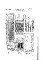
Figure 1 is a vertical section evaporating unit and race,
Figure 2 is a plan view showing a portion of the evaporating coils,
Figure 3 is an end View of unit and race as applied toan ice making tank and shows a portion of the chamber in which the ice cans are mounted,
Figure 4 is an enlarged detail showing the nesting of evaporating coils, and
Figure 5 is a diagrammatic plan view of the race in a tank for cooling liquid such as brine in an ice making tank, water, oil, etc.
In the drawings, numeral 10 indicates a tank having a partition .11 running either lengthwise as shown in Figure 5 or crosswise to provide a chamber 12 in which ice cans 13 may be placed or which may act as a liquid storage space and a race 14 in which an evapcrating unit 15 may be placed. A pump 16 of any suitable construction may be provided for circulating liquid through the race 14 to bring it into contact with the evaporator 15 and to circulate it through the brine chamber 12. Instead of one partition 11 together with tank side 10 forming the sides of the race,
through the the evaporating two partitions '11 middle of the tank a. The evaporator unit 15 will now'be described. This consists of a pair of upper headers 17 and 18 and lower headers 19 and 20, the latter being connected with a source of liquid refrigerant in a receiver not shown and the upperheaders being connected to the may be run through the to form the race.
suction side of the refrigerant compressing and cooling system. The ;upper headers are" connected by transverse pipes 21 and the lower headers by similar transverse pipes 22. Bowed tubes 23 are connected to the upper and lower transverse pipes 21and 22 and these tubes are bent so as to nest one within the other, being here shown as bent into W-shaped pipes. These pipesmay andpreferably' are bent near their ends as shown at 24' as they enter 22. The purpose of this is to simplify the problem of securing these tubes to the transverse pipes. As shown in F igures 2 and 1 the tubes 22- are staggered thus entering alternate the transverse pipesx21' and transverse pipes So as to provide sufiicient space'between adjacent tubes '23 to permit attaching to transverse pipes 21 and 22 and still get very c ose nesting of tubes in the unit. If the desired spacing of tubes in the unit is wider, the tubes need not be staggered. The headers 17, 18, 19 and 20 may be supported bya suitable frame work constituting supports 25 andbraces 26 arranged in any convenient form and of sufiicient strength to support tubes of the necessary size. The coil unit 15 therefore may be readily removed from the brine tank and replaced by'additional coil units or be removed to repair or replace a single tube from the coils which for any reason may become damaged. j
Securedto the top of the race Mare bafiie. plates 27 which extend from the top of the evaporator unit 15 towards the top of the race and whose function .is to maintain relatively still liquid in the race above the'evaporator unit 15 with a relatively rapid flow of liquid past theevaporator 15. The tendency of the agitator 16, of course, is'to have a rather high a liquid level at the inlet end of the race 14 with a lower level attheoutlet end. In order levelbetween race inlet and outlet. The rela- 14 and tank 12 should It is desired to circulate the liquid tive sizes of the race be noted.
throughthe race 14 at a much greater rate than e that with which it travels throughthe tank. The relative speeds with which the liquid may pass through the race 1 and chamber 12 may be determined by their relative sizes. While we have shown a single race and a single agitator, we may find it desirable to place anumber of races and agitators in various locations in the tank.
While in the above description we have dealt with liquids, any other fluids such as gases or finely divided solids which will flow may be cooled with the evaporating unit described. It is obvious that for gases, race would be replaced by a gas tight enclosing duct. v While with liquids, the flow imposing means would be pumps, propellers, paddles, etc.; fans, blowers or compressors would be used for gases; and conveyors or screws for the solids.
It is obvious that by omitting the race the 3. A cooling system for liquids having a channel with an evaporating unit therein for cooling the liquid, baflies across the top of the channel sloping upward from the evaporating unit toward the channel entrance, an means for circulating the'liquid through the channel, substantially as set forth. l. An evaporator for a refri crating system comprising. a plurality .0 lower headers having a plurality of nested bowed tubes'connecting them, means .for directing a fluid to be cooled about said tubes, and a plurality of relatively short baffle plates positioned oblique with respect to the headers and the normal direction of the fluid through the tubes for directing the said Ifluid into better heat exchange contactwith the tubes, substantially as set forth. .7
In witness whereof, we have hereunto set our hands at Waynesboro,'Pennsylvania this 23rd day of December, A. D. nineteen hun-' dred and twenty-nine.
' LEON BUEHLER, JR. 7
WILLIAM H. AUBREY.
and placing the evaporating unit near the V top of the fluid space, circulation of the fluid may be accomplished by natural means without the use of mechanical pumps, etc.
It will be obvious to those skilled in the artthat various changes may be made in our device without departing from the spiritof the invention and therefore we do not limit ourselves to what is shown in the drawings and described in the as indicated in the appended claims.
Having thus fully described our said invention, what we claim as new and desire to secure by Letters Patent, is: 1. An evaporator for a refrigerating system comprising a pair of upper headers'having transverse headers connecting them, a pair of lower headers having transverse headers connecting them, a plurality of bowed-tubes connected in spaced relation to the upper and lower transverse headers, the said bowed tubes being bent in the form of Ws and having their ends slightly bent to enter the transverse headers, substantially as set forth.
2. A cooling system for liquids having a channel with an evaporating unit therein for cooling thejliquids,'bafiies across the top of q the channel extending from the top of the evaporating unit upwards, and means for 011- culating the liquid through the channel, substantially as set forth. a
specification but only upper and
Priority Applications (1)
| Application Number | Priority Date | Filing Date | Title |
|---|---|---|---|
| US418932A US1857078A (en) | 1930-01-06 | 1930-01-06 | Refrigerating system |
Applications Claiming Priority (1)
| Application Number | Priority Date | Filing Date | Title |
|---|---|---|---|
| US418932A US1857078A (en) | 1930-01-06 | 1930-01-06 | Refrigerating system |
Publications (1)
| Publication Number | Publication Date |
|---|---|
| US1857078A true US1857078A (en) | 1932-05-03 |
Family
ID=23660135
Family Applications (1)
| Application Number | Title | Priority Date | Filing Date |
|---|---|---|---|
| US418932A Expired - Lifetime US1857078A (en) | 1930-01-06 | 1930-01-06 | Refrigerating system |
Country Status (1)
| Country | Link |
|---|---|
| US (1) | US1857078A (en) |
-
1930
- 1930-01-06 US US418932A patent/US1857078A/en not_active Expired - Lifetime
Similar Documents
| Publication | Publication Date | Title |
|---|---|---|
| US3296824A (en) | Multiple pump system for absorption apparatus | |
| US2523529A (en) | Eliminator for refrigeration system evaporators | |
| US3145542A (en) | Self-sustained liquid circulating seal system | |
| US1857078A (en) | Refrigerating system | |
| US3859820A (en) | Compressor, condenser, evaporator structure | |
| US1783464A (en) | Refrigerating machine | |
| US3257817A (en) | Refrigeration apparatus and method | |
| US2221423A (en) | Refrigerating apparatus | |
| US3215193A (en) | Latent heat storage tank | |
| US2329746A (en) | Refrigerating apparatus | |
| US2345454A (en) | Refrigeration | |
| US2716870A (en) | Reverse cycle heat pump system | |
| US3357202A (en) | Absorption refrigerating machine | |
| US2188349A (en) | Hold-over refrigeration unit | |
| US10989452B2 (en) | Channeled condenser ballast | |
| US1797764A (en) | Refrigeration | |
| US1718310A (en) | Method of and apparatus for cooling liquids | |
| US2274659A (en) | Refrigeration | |
| US2115715A (en) | Air conditioning apparatus | |
| US1914300A (en) | Evaporator for refrigerators | |
| US1786163A (en) | Condenser for mixed vapors | |
| US2268381A (en) | Refrigeration | |
| US1718311A (en) | Evaporator and brine cooler | |
| US2877631A (en) | Refrigeration apparatus | |
| US2297280A (en) | Refrigeration |