US1857071A - Board-feet computer - Google Patents
Board-feet computer Download PDFInfo
- Publication number
- US1857071A US1857071A US490032A US49003230A US1857071A US 1857071 A US1857071 A US 1857071A US 490032 A US490032 A US 490032A US 49003230 A US49003230 A US 49003230A US 1857071 A US1857071 A US 1857071A
- Authority
- US
- United States
- Prior art keywords
- board
- roller
- cone
- shaft
- carriage
- Prior art date
- Legal status (The legal status is an assumption and is not a legal conclusion. Google has not performed a legal analysis and makes no representation as to the accuracy of the status listed.)
- Expired - Lifetime
Links
- 238000005266 casting Methods 0.000 description 8
- 239000000463 material Substances 0.000 description 5
- 238000010276 construction Methods 0.000 description 4
- 230000005484 gravity Effects 0.000 description 2
- 239000002184 metal Substances 0.000 description 2
- 238000003466 welding Methods 0.000 description 2
- 241001665400 Coracias abyssinicus Species 0.000 description 1
- 230000006835 compression Effects 0.000 description 1
- 238000007906 compression Methods 0.000 description 1
- 238000004883 computer application Methods 0.000 description 1
- 238000005520 cutting process Methods 0.000 description 1
- 235000000396 iron Nutrition 0.000 description 1
- 210000003141 lower extremity Anatomy 0.000 description 1
Images


Classifications
-
- G—PHYSICS
- G01—MEASURING; TESTING
- G01F—MEASURING VOLUME, VOLUME FLOW, MASS FLOW OR LIQUID LEVEL; METERING BY VOLUME
- G01F17/00—Methods or apparatus for determining the capacity of containers or cavities, or the volume of solid bodies
Definitions
- This invention relates to measuring instruments broadly and particularly to a machine for registering the number of'board feet in boards of different thickness, width and length, the main object being to provide a machine that, is simple in construction, has relatively few parts, and is accurate in performing its intended functions.
- Another object of the invention is to pro- Vide a machine of the classindicated that is entirely automatic in adjusting itself to each of the three dimensions of a board, it being only necessary to feed the boardthrough the machine and read the registered indication after it has passed through.
- a further and more specific object of the invention is to provide in a boardn1easuring machine of the type indicated, a pair of coni cal or tapered elements, one for the thickness and the other for the width of the board, each of said elements-having an associated roller.
- One of the rollers isadapted to be moved along its associated cone in accordance with the thickness of the board, while the other roller is stationary and the second cone is adapted to be moved relative thereto in accordance with the width of the board.
- the motion imparted to one cone bythe moving board is in turn imparted to the second cone 30 through the medium of a pair of gears and the roller associated with the second cone.
- the shaft of the second cone drives a rotation counter or indicating device of any suitable type.
- rollers and cones to automatically adjust themselvesin accordance with the dimensions of the board.
- One roller is actuated by gravity to adjust the position thereof relative to its associated cone in accordance with the thickness of the board, while the second cone is actuated by a counterweight to adjust the position thereof relative to its associated roller in accordance with the width of the board.
- Spring means-are utilized to cause a constant bearing pressure to be exertecl by the cones and rollersupon each other, the
- a horizontal table 1 which may be comprised of suitable metal, supported by a; plurality of angle irons2
- the angle irons which support the table may be disposed in the form ofarectangleand welded together at'the corners of the rectangle.
- This structure maybe supported by a plurality of leg, members 3, which may comprise angle members welded or secured to the horizontally-disposed angles in any suitable manner,
- One of the horizontally-disposed angles 2 which support the table lis divided into'two parts and has associ- 5 ated therewith, preferably by welding, a
- a casting 5 is bridged. across the framework formed by the previously mentioned angles 2, and is attached to such angles by means of a plurality of bolts 4.
- This casting may take the form shown in the drawings, and is provided with a central upstanding portion which supports an inclined boss 6.
- Boss 6 has bulged end portions 8 and 9, which are adapted to house suitable thrust bearings for a rotatable shaft mounted within the boss.
- the casting 5 is also formed to provide a centrally and horizontally-disposed boss 7, which also has bulged end portions 10 and 11 adapted to house suitable bearings for the rotatable mountingof a shaft passing through and supported by the boss member.
- the inclined shaft which is supported by boss 6 is provided at its upper end with a conical or tapered member 12.
- the inclination ofthe shaft and the design of the cone are suchthat one element of the conical surface lies in or is. tangent to a vertical plane.
- a bevelgear 13 is provided at the other end of the inclinedshaft.
- One end of the horizontallydisposed shaft, which is supported by boss 7 is provided with a roller 14.
- the other ,end of this shaft is provided with a bevel gear 15 which meshes with gear 13 on the inclined sha-ft.
- Casting 5 is also provided with a depend ing boss 16 at one side thereof, the purpose of which will be apparent later.
- a second casting 17 is supported upon casing 5, and is provided at'its ends with "bosses 18 and 19.
- This latter bridge member is disposed with respect to casting 5.so that boss portion 19 is directly above boss 16.
- a yoke 20 havingthe shape of an inverted U is supported by bridge members or castings 5 and 17. This yoke has 40 a pair of arms 21 and 22, which extend into the boss portions of the bridge member 17. Arm21 extends only partially through boss 18, while arm 22 extends entirely through boss 19 and boss 16, thearms being secured by means of suitable pins or the like to bosses 18 and 19.
- Arm 22 is provided on its lower extremity with a collar 78 which is pinned to the arm.
- the yoke also comprises an arch portion 23,. which is attached to the upper ends of the arms.
- Arms 21 and 22 form guide rods for a roller-supporting bracket 24.
- This bracket is bridged between the arms and has sleeve portions 25 and 26 which are slidable upon the rods.
- Sleeve 25 is provided with a fiat surface, to which a skid-supporting member 27 is attached by means ofsuitable bolts.
- Skid 28 is attached to a surface of support 27. The purpose of the skid is to raise the roller-supporting bracket when engaged by a board, as will appear more clearly hereinafter.
- Bracket 24 has its'central portion formed to provide a boss 29 having bulged end portions for housing thrust bearings to accommodate a rotatable shaft. Bracket 24 may, of course, be formed as a casting. A roller 30 is provided on the upper end of the shaft which is supported by boss 29, while a roller 31 is carried on the lower end of the shaft.
- roller 30 is adapted to'bear against cone 12 to actuate the same.
- the central portion of bracket 24 is also formed to'provide an extending portion 32, to which a roller 33 is attached.
- a board 34 whose board feet it is desired to measure, slides along table 1 and its edge is engaged by roller 31 while its upper surface is engaged by roller 33.
- the bracket 24 and the rollers carried thereby are carried downward by gravity until roller 33 restsagainst the top rollers carried thereby drop after a boardhas passed through'the device, a pair of coil springs 35 and 36 are.
- a pair of rests 37 and 38' are provided above the springs, upon which the end portions: of bracket 24- are 1 adaptedto rest.
- a carriage support 41 is pivotally supported by the angle framework, as indicated at 42.
- This support comprises a pair of parallel tracks 43 and 44, as shown clearly in Fig. 2, having their ends bent upward and bridged by an angle member 45, (see Fig. 4).
- Support 41 is adapted to support carriage 46,
- roller shafts 47 and 48 which is provided with a pair of transverser ly-extending roller shafts 47 and 48 at its ends. These shafts carry pairs of rollers 49 and 50 respectively, which engage the upper surfaces of tracks 43 and 44.
- the body portion of the carriage is T-shaped in cross section and lies between the tracks (see Fig. Aleaf-spring 51 is supported at one end upon the carriageand carries at its other end a roller-supporting bracket 52, which carries at its ends a pair of rollers 53. These rollers, due to the action of spring 51, exert a constant upward pressure on the lower surface of tracks 43' and 44.
- a second conical-or taperedv member 54 is so that an element of its conical surface is horizontal or tangent to a horizontal plane.
- the conical surface of this member is adapted to be engaged by roller 14.
- Thecone 54 is provided with a suitable shaft, and one end of the shaft is carried in a bearing'bracket 55 supported on shaft 48, while the other end of the shaft is suitably journaled in the opposite upstanding portion of the carriage body, as indicated at 56.
- This upstanding portion of the carriage extends through an opening 57 in table 1, (see Fig. 2) and is provided at its upper end with a handle 58 which may be integral with the carriage. It is also provided with the roller 59, which engages the edge of the board opposite to that engaged by roller 31.
- the upper end of this upstanding portion of the carriage is also provided with a skid 60.
- the carriage is adapted to move horizontallyalong tracks 43 and 44.
- the width of the particularboard being measured will, of course, determine the position of the carriage along. the tracks.
- Skid 60 functions tomove the carriage when it is engaged by the end of a board being fed into the machine.
- an angle 2 I which bridges the ends of the framework has attached thereto, preferably by welding,-a depending plate support 61.
- This support has its lower portion bent horizontally and carries a pair of journaledshafts 62 and 63.
- the upper ends of these shafts extend through openings in the horizontal portion of angle. 45, and the angle is slidable along these shafts.
- the upper ends of the shafts are rotatably mounted in the angle framework, as
- a pair of coil springs 64 and 65 are carried on shafts 62 and 63 between suitable cup members 66.
- the lower cup members are prevented from turning by having extending lugs 67, which protrude through slots in the plate support 61.
- These lower cup members arethreaded and receive the lower threaded portions of shafts 62 and 63.
- Shaft 62 and its cup are provided with right hand threads while shaft 68 and its cup are provided withleft hand threads.
- a pair of bevel gears 68 and 69 are provided on the lower ends of the shafts and mesh with the bevel gear portions of a single gear member 70.
- This latter gear'member is provided at its central portion with a sprocket 71, and is carried on shaft 72, which is mounted between a pair of depending arms 73.
- a chain 74 is attached at one end to carriage 46, and passes around sprocket 71. and a suitable pulley 75. The chain carries at its other end a counterweight 76.
- springs 64 and 65 course, to exert an upward pressure on the carriage support by urging upper cup 66 and angle member 45 upward, as is apparent in Fig. 4, .to thereby cause a continuous pressure between roller '14 and, cone 54. It will be apparent that. the position of the carriage along its supporting tracks will determine the force whichmust be overcome by springs 64 and 65 to maintain cone 54 in contact with roller 14-with a constant pressure. When the carriage is at the outer end of the support, the leverage is greater and the springs must exert a greater force, while when the carriage is at the inner end of its support, the leverage is less and a smaller force is required.
- the sprocket As the carriage moves toward the inner end of its support the sprocket is rotated clockwise and the springs will be permitted to expand downwardly, thereby lessening the compressional force exerted by them on thecarriagesupporting assembly. It will be obvious that the device may be designed and calibrated'so that the variation of the tension of the springs exactly compensates for variations in leverage, .due to movement of the carriage.
- a suitable rotation counter. or indicator of any desired type 77 is mounted by means of a bracket 78 on the table-supporting structure.
- the shaft of this indicator is connected by means of a. flexible shaft 79 to the shaft of cone 54. Rotation of cone 54 will, therefore, cause rotationof the indicator shaft through the medium of shaft 79;
- indicator 77 may have its scale calibrated to read not only the number of rotations made, but also the number of board feet in the board being measured. Since the number or revolutions made by the shaft 54 during the measuring of acertain board is diproportional to the board feet con- During inoperative periods of the device,
- roller 59 The action of the counterweight will cause roller 59 to bear continually against one. edge of the board.
- the thickness of the board will, of course, determine theposition of roller along cone 12, while the width of the board will determine the position of the carriage and, therefore, the point of engagement of roller 14 along the cone 54'.
- roller 30 is thereby rotated and imparts motion to cone 12.
- the rate of rotation of the inclined shaft depends, of course," upon the portion of the cone engaged by the roller. I
- the shaft of cone 12 imparts motion to the roller 14 through the medium of beveled gears 13 and 15.
- Roller 14 causes rotation of cone 54, the rate of rotation of cone 54'b-eing determined by the point of engagement of the roller with the cone.
- the rate of rotation of the indicator shaft is determined entirely by the two dimensions, viz., the thickness and width of the board.
- the length of the board determines the total number of revolutions at the particular rate.
- r r I the-device may be used to measure either finished or unfinished lumber. Since the total thickness of the cuttings taken off the different sizes of unfinished boardsby planing, etc. is known, the device could be arranged to be adjustable to give the reading in board feet of unfinished lumber, although finished lumber is being passed through it. For example, the position of roller 30 with respect to cone 12 could be adjustable to compensate for the amount taken off the board in finishing the same. This could be accomplished in various ways.
- means for slidably receiving a three dimensional piece of material means, comprising a rotatable member having roller contact zones of different diameters, said member being operable proportionately to a dimension of said piece of material, means, comprising a roller engaging with said member and adapted to be engaged with the sliding piece of material, for actuating said member, and means for relatively associating said member and said roller to establish therebetween a velocity ratio in accordance with the said dimension of said piece of material.
- a device of the class described comprising means for slidably receiving a board endwise, indicating means, means, comprising a plurality of rollers and a corresponding plurality of rotatable members each having roller contact zones of different diameters, said members respectively engaging with said rollers, for actuating said indicating means from the sliding board proportionately to the three dimensions of said board, and means for causing constant pressure between said rollers and members.
- a device of the class described comprising means for slidably receiving a board endwise, indicating means, means, comprising a plurality of rollers and a corresponding plurality of rotatable conical members respectively engaging with said rollers, for actuating said indicating means from the sliding board proportionately to the threedimensions of said board, and means for causing constant pressure between said rollers and conical members.
- a device of the class described comprising means for slidably receiving a board endwise, a second means operable proportionately to the thickness of said board, a third means for actuating said second means from the sliding board proportionately to the board thickness, a fourth means operable by said second means proportionately to the width of said board, means for relatively associating said second means and the means operable thereby so asto establish therebetween ios a velocity ratio in accordance with the board width, indicating means, and driving means therefor operable by said fourth means.
- a device of the class described comprising means for slidably receiving a board endwise, a second means operable proportionately to the thickness of said board, a third means for actuating said second means from the sliding board proportionately to the board thickness, a fourth means operable by said second means proportionately to the width of said board, means for relatively associating said second means and the means operable thereby so as to establish therebetween a velocity ratio in accordance with the board width, indicating means, and driving means therefor operable by said fourthmeans, said second and fourth means each comprising a rotatable member having roller contact zones of different diameters, and said third and second means each comprising a. roller respectively engaging with said members.
- a device of the class described comprising means for slidably receiving a board endwise, a second means operable proportionately to the thickness of said board, a third means for actuating said second means from the sliding board proportionately to the board thickness, a fourth means operable by said second means proportionately to the width of said board, means for relatively associating said second means and the means operable thereby so as to establish therebetween a velocity ratio in accordance with the board width, indicating means, driving means therefor operable by said fourth means, said second and fourth means each comprising a rotatable member having roller contact zones of different diameters, and said third and second means each comprising a roller respectively engaging with said members, and means for causing constant pressure between said rollers and members.
- a second means comprising a longitudinally fixed rotatable cone operable proportionately to the thickness of said board
- a third means comprising an axially movable roller engaging said cone and adapted to be driven from the sliding board, for actuating said second means
- a fourth means for axially moving said roller in accordance with the board thickness
- a fifth means comprising a longitudinally movable rotatable cone operable by said second means proportionately to the width of said board, means for positioning said movable cone relative to said second means to establish therebetween a velocity ratio in accordance with the board width, indicating means, and driving means therefor operable by said fifth means.
- a device of the class described means for slidably receiving a board endwise, a second means operable proportionately to the thickness of said board, said last means comprising a longitudinally fixed rotatable cone and a roller driven thereby, a third means, comprising an axially movable roller engaging said cone and adapted to be driven from the sliding board, for actuating said second means, a fourth means for axially moving said roller in accordance with the board thickness, a fifth means operable by said second means proportionately to the width of said board, said fifth means comprising a longitudinally movable rotatable cone contacting said first named roller, means for positioning said movable cone relative to said first named roller to establish therebetween a velocity ratio in accordance with the board width, means for causing a constant pressure between said rollers and cones, indicating means, and driving means therefor operable by said fifth means.
Landscapes
- Physics & Mathematics (AREA)
- Fluid Mechanics (AREA)
- General Physics & Mathematics (AREA)
- A Measuring Device Byusing Mechanical Method (AREA)
Description
May 3, 1932. M. G. TULL BOARD FEET COMPUTER Filed Oct. 20, 1930 5 Sheets-Sheet mw w? a? B m? May 3, 1932. M. s. TULL BOARD FEET COMPUTER 20, 1950 3 Sheets-Sheet Filed Oct.
May 3, 1932. M. G. TULL 1,857,071
BOARD FEET COMPUTER Filed Oct. 20, 1930 3 Sheets-Sheet Z3 gaiamjjifi'r s Patented May 3, 1932 UNITED STATES MONTROSE GRAHAM TULL, F WAYNE, PENNSYLVANIA BOARD-FEET COMPUTER Application filed October 20, 1930. Serial No. 490,032. a
This invention relates to measuring instruments broadly and particularly to a machine for registering the number of'board feet in boards of different thickness, width and length, the main object being to provide a machine that, is simple in construction, has relatively few parts, and is accurate in performing its intended functions.
Another object of the invention is to pro- Vide a machine of the classindicated that is entirely automatic in adjusting itself to each of the three dimensions of a board, it being only necessary to feed the boardthrough the machine and read the registered indication after it has passed through. I
A further and more specific object of the inventionis to provide in a boardn1easuring machine of the type indicated, a pair of coni cal or tapered elements, one for the thickness and the other for the width of the board, each of said elements-having an associated roller. One of the rollers isadapted to be moved along its associated cone in accordance with the thickness of the board, while the other roller is stationary and the second cone is adapted to be moved relative thereto in accordance with the width of the board. The motion imparted to one cone bythe moving board is in turn imparted to the second cone 30 through the medium of a pair of gears and the roller associated with the second cone. The shaft of the second cone, in turn, drives a rotation counter or indicating device of any suitable type. The construction outlined above and which is described. more in detail hereinafter results in an extremely simple and accurate device;
An important feature of theinvention is the design and arrangement of parts to cause the rollers and cones to automatically adjust themselvesin accordance with the dimensions of the board. One roller is actuated by gravity to adjust the position thereof relative to its associated cone in accordance with the thickness of the board, while the second cone is actuated by a counterweight to adjust the position thereof relative to its associated roller in accordance with the width of the board. Spring means-are utilized to cause a constant bearing pressure to be exertecl by the cones and rollersupon each other, the
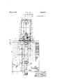
tension 'ofthe springs associated with the 7 second conebeing. varied by means operated by the said counterweight to compensate for variations in pressure, of the said coneupon its roller due to different positions of the ne r The aboveand other objects and features of theinvention, as well as the details of con structionof; a single embodiment thereof, will be clearly understood from the following detailed description read in connection with theaccompanying drawings. ,n 7 Inthedrawings: I 4 Fig." 1 is a side elevation of the the invention; a i V Fig.2 is a plan view of the device of Fig. 1; Fig. 3'is a sectional view along line 3-3 ofFig. 1; and
device of Fig. 4 is a sectional yiew along line 44 of Fig. 1. Y Referring to thedrawings, and particularly to Fig. 1, there is shown a horizontal table 1 which may be comprised of suitable metal, supported by a; plurality of angle irons2 The angle irons which support the table may be disposed in the form ofarectangleand welded together at'the corners of the rectangle. This structure maybe supported by a plurality of leg, members 3, which may comprise angle members welded or secured to the horizontally-disposed angles in any suitable manner, One of the horizontally-disposed angles 2 which support the table lis divided into'two parts and has associ- 5 ated therewith, preferably by welding, a
plurality of other horizontally-disposed angles also indicated by the reference character 2 and shown clearly in Fig. 2. The arrangement of these latter angles is such aswill provide an extending framework for supporting various elements of the device, as will appear more clearly hereinafter. While the angle framework which supports the various elements of the device is, in thepresent instance, shown as supported by means. of a pluralitv of legs, it will be readily understood that this framework may be supported in any desired manner, and could be attached 1 to a wood-working machine, such as a planing machine.
Referring to Figs. 1 to 3, a casting 5 is bridged. across the framework formed by the previously mentioned angles 2, and is attached to such angles by means of a plurality of bolts 4. This casting may take the form shown in the drawings, and is provided with a central upstanding portion which supports an inclined boss 6. Boss 6 has bulged end portions 8 and 9, which are adapted to house suitable thrust bearings for a rotatable shaft mounted within the boss. The casting 5 is also formed to provide a centrally and horizontally-disposed boss 7, which also has bulged end portions 10 and 11 adapted to house suitable bearings for the rotatable mountingof a shaft passing through and supported by the boss member. The inclined shaft which is supported by boss 6 is provided at its upper end with a conical or tapered member 12. The inclination ofthe shaft and the design of the cone are suchthat one element of the conical surface lies in or is. tangent to a vertical plane. A bevelgear 13 is provided at the other end of the inclinedshaft. One end of the horizontallydisposed shaft, which is supported by boss 7 is provided with a roller 14. The other ,end of this shaft is provided with a bevel gear 15 which meshes with gear 13 on the inclined sha-ft. v y
, Casting 5 is also provided with a depend ing boss 16 at one side thereof, the purpose of which will be apparent later. A second casting 17 is supported upon casing 5, and is provided at'its ends with " bosses 18 and 19. This latter bridge member is disposed with respect to casting 5.so that boss portion 19 is directly above boss 16. A yoke 20 havingthe shape of an inverted U is supported by bridge members or castings 5 and 17. This yoke has 40 a pair of arms 21 and 22, which extend into the boss portions of the bridge member 17. Arm21 extends only partially through boss 18, while arm 22 extends entirely through boss 19 and boss 16, thearms being secured by means of suitable pins or the like to bosses 18 and 19. Arm 22 is provided on its lower extremity with a collar 78 which is pinned to the arm. The yoke also comprises an arch portion 23,. which is attached to the upper ends of the arms. Arms 21 and 22 form guide rods for a roller-supporting bracket 24. This bracket is bridged between the arms and has sleeve portions 25 and 26 which are slidable upon the rods. Sleeve 25 is provided with a fiat surface, to which a skid-supporting member 27 is attached by means ofsuitable bolts. Skid 28 is attached to a surface of support 27. The purpose of the skid is to raise the roller-supporting bracket when engaged by a board, as will appear more clearly hereinafter. Bracket 24 has its'central portion formed to provide a boss 29 having bulged end portions for housing thrust bearings to accommodate a rotatable shaft. Bracket 24 may, of course, be formed as a casting. A roller 30 is provided on the upper end of the shaft which is supported by boss 29, while a roller 31 is carried on the lower end of the shaft.
As shown clearly in Figs. 1 to 3, roller 30 is adapted to'bear against cone 12 to actuate the same. The central portion of bracket 24 is also formed to'provide an extending portion 32, to which a roller 33 is attached. It will be apparent from Fig. 1 that a board 34, whose board feet it is desired to measure, slides along table 1 and its edge is engaged by roller 31 while its upper surface is engaged by roller 33. The bracket 24 and the rollers carried thereby are carried downward by gravity until roller 33 restsagainst the top rollers carried thereby drop after a boardhas passed through'the device, a pair of coil springs 35 and 36 are. provided, as shown more clearly in Fig. 3. A pair of rests 37 and 38' are provided above the springs, upon which the end portions: of bracket 24- are 1 adaptedto rest.
It illbe noted. that there will be a tendency for, the arm 22 to. rotate within boss 16.
.To counteract thisand to cause a constant frictional engagement between cone 12 and roller 30 at all times, Iprovide a spring 39 which is fastened between bridge 17 and bridge -5,.as shownclearly. in Fig. 2. This spring may be fastened to the bridge members by means of suitable bolts, one of which may provide an adjustment as indicated at A carriage support 41 is pivotally supported by the angle framework, as indicated at 42. This support comprises a pair of parallel tracks 43 and 44, as shown clearly in Fig. 2, having their ends bent upward and bridged by an angle member 45, (see Fig. 4). Support 41 is adapted to support carriage 46,
which is provided with a pair of transverser ly-extending roller shafts 47 and 48 at its ends. These shafts carry pairs of rollers 49 and 50 respectively, which engage the upper surfaces of tracks 43 and 44. The body portion of the carriage is T-shaped in cross section and lies between the tracks (see Fig. Aleaf-spring 51 is supported at one end upon the carriageand carries at its other end a roller-supporting bracket 52, which carries at its ends a pair of rollers 53. These rollers, due to the action of spring 51, exert a constant upward pressure on the lower surface of tracks 43' and 44.
A second conical-or taperedv member 54 is so that an element of its conical surface is horizontal or tangent to a horizontal plane. The conical surface of this member is adapted to be engaged by roller 14. Thecone 54 is provided with a suitable shaft, and one end of the shaft is carried in a bearing'bracket 55 supported on shaft 48, while the other end of the shaft is suitably journaled in the opposite upstanding portion of the carriage body, as indicated at 56. This upstanding portion of the carriage extends through an opening 57 in table 1, (see Fig. 2) and is provided at its upper end with a handle 58 which may be integral with the carriage. It is also provided with the roller 59, which engages the edge of the board opposite to that engaged by roller 31. The upper end of this upstanding portion of the carriage is also provided with a skid 60.
It will be apparent that the carriage is adapted to move horizontallyalong tracks 43 and 44. The width of the particularboard being measured will, of course, determine the position of the carriage along. the tracks. Skid 60 functions tomove the carriage when it is engaged by the end of a board being fed into the machine.
Referring to Fig. 4, an angle 2 I which bridges the ends of the framework has attached thereto, preferably by welding,-a depending plate support 61. This support has its lower portion bent horizontally and carries a pair of journaledshafts 62 and 63. The upper ends of these shafts extend through openings in the horizontal portion of angle. 45, and the angle is slidable along these shafts. The upper ends of the shafts are rotatably mounted in the angle framework, as
shown clearly in Fig. 1. A pair of coil springs 64 and 65 are carried on shafts 62 and 63 between suitable cup members 66. The lower cup members are prevented from turning by having extending lugs 67, which protrude through slots in the plate support 61. These lower cup membersarethreaded and receive the lower threaded portions of shafts 62 and 63. Shaft 62 and its cup are provided with right hand threads while shaft 68 and its cup are provided withleft hand threads.
A pair of bevel gears 68 and 69 are provided on the lower ends of the shafts and mesh with the bevel gear portions of a single gear member 70. This latter gear'member is provided at its central portion with a sprocket 71, and is carried on shaft 72, which is mounted between a pair of depending arms 73. A chain 74 is attached at one end to carriage 46, and passes around sprocket 71. and a suitable pulley 75. The chain carries at its other end a counterweight 76. Since the threads on the lower port- ions ofshafts 62 and 63 are respectively right and left hand threads, rotation of the sprocket and gear in a certain direction will cause both of the lower spring-supporting cup members to raise or lower as the case may be.
The purpose of springs 64 and 65 course, to exert an upward pressure on the carriage support by urging upper cup 66 and angle member 45 upward, as is apparent in Fig. 4, .to thereby cause a continuous pressure between roller '14 and, cone 54. It will be apparent that. the position of the carriage along its supporting tracks will determine the force whichmust be overcome by springs 64 and 65 to maintain cone 54 in contact with roller 14-with a constant pressure. When the carriage is at the outer end of the support, the leverage is greater and the springs must exert a greater force, while when the carriage is at the inner end of its support, the leverage is less and a smaller force is required.
To provide a varying tension in springs 64 and 65,- so that the variations in force required by different positions of the carriage may be obtained, I have providedthearrangement which is actuated by thesprocket and chain. It will be noted that as the car riage moves toward the outer end of its support, due tothe counterweight, the sprocket will be rotated counter-clockwise and its associated gears will rotate shafts 62 and 63, thereby. raising the lower spring-supporting cup members. This will cause a compression of springs 64 and 65 to thereby cause them to exert a greater upward pressure on the carriage-supporting assembly. As the carriage moves toward the inner end of its support the sprocket is rotated clockwise and the springs will be permitted to expand downwardly, thereby lessening the compressional force exerted by them on thecarriagesupporting assembly. It will be obvious that the device may be designed and calibrated'so that the variation of the tension of the springs exactly compensates for variations in leverage, .due to movement of the carriage.
A suitable rotation counter. or indicator of any desired type 77 is mounted by means of a bracket 78 on the table-supporting structure. The shaft of this indicator is connected by means of a. flexible shaft 79 to the shaft of cone 54. Rotation of cone 54 will, therefore, cause rotationof the indicator shaft through the medium of shaft 79; It will be apparent that indicator 77 may have its scale calibrated to read not only the number of rotations made, but also the number of board feet in the board being measured. Since the number or revolutions made by the shaft 54 during the measuring of acertain board is diproportional to the board feet con- During inoperative periods of the device,
is, of
thickness of the board. The action of the counterweight will cause roller 59 to bear continually against one. edge of the board. The thickness of the board will, of course, determine theposition of roller along cone 12, while the width of the board will determine the position of the carriage and, therefore, the point of engagement of roller 14 along the cone 54'. 'As the board moves along the table and actuates roller 31, roller 30 is thereby rotated and imparts motion to cone 12. The rate of rotation of the inclined shaft depends, of course," upon the portion of the cone engaged by the roller. I The shaft of cone 12, in turn, imparts motion to the roller 14 through the medium of beveled gears 13 and 15. Roller 14 causes rotation of cone 54, the rate of rotation of cone 54'b-eing determined by the point of engagement of the roller with the cone. It will, therefore, be seen that the rate of rotation of the indicator shaft is determined entirely by the two dimensions, viz., the thickness and width of the board. The length of the board, of course, determines the total number of revolutions at the particular rate. r r I Obviously, the-device may be used to measure either finished or unfinished lumber. Since the total thickness of the cuttings taken off the different sizes of unfinished boardsby planing, etc. is known, the device could be arranged to be adjustable to give the reading in board feet of unfinished lumber, although finished lumber is being passed through it. For example, the position of roller 30 with respect to cone 12 could be adjustable to compensate for the amount taken off the board in finishing the same. This could be accomplished in various ways.
It will be seen that I have devised a device whose constructionembodies various new and novel features which collectively simplify the construction and add greatly to the efliciency of the machine. It will be apparent to persons skilled in the art that various changes in the details of construction may be made without departing from the spirit and scope of the invention. It will be understood, of course, that the device may be used to measureslabs of metal, etc., as well as boards.
I desire it tobe understood,therefore, that my invention is not to be limited by the single embodiment disclosed herein, or by the various details which are contained in that embodiment. The invention is to be limited only as is required by the prior art. Limitations only which are contained in the accompanying claims, in view of the prior art,
respectively engaginglwith said rollers, for
actuating said indicating means from the sliding piece proportionately to the three dimensions of said piece of material.
2. In a device of the class described, means for slidably receiving a three dimensional piece of material, means, comprising a rotatable member having roller contact zones of different diameters, said member being operable proportionately to a dimension of said piece of material, means, comprising a roller engaging with said member and adapted to be engaged with the sliding piece of material, for actuating said member, and means for relatively associating said member and said roller to establish therebetween a velocity ratio in accordance with the said dimension of said piece of material.
3. A device of the class described comprising means for slidably receiving a board endwise, indicating means, means, comprising a plurality of rollers and a corresponding plurality of rotatable members each having roller contact zones of different diameters, said members respectively engaging with said rollers, for actuating said indicating means from the sliding board proportionately to the three dimensions of said board, and means for causing constant pressure between said rollers and members. i
4. A device of the class described comprising means for slidably receiving a board endwise, indicating means, means, comprising a plurality of rollers and a corresponding plurality of rotatable conical members respectively engaging with said rollers, for actuating said indicating means from the sliding board proportionately to the threedimensions of said board, and means for causing constant pressure between said rollers and conical members.
5. A device of the class described comprising means for slidably receiving a board endwise, a second means operable proportionately to the thickness of said board, a third means for actuating said second means from the sliding board proportionately to the board thickness, a fourth means operable by said second means proportionately to the width of said board, means for relatively associating said second means and the means operable thereby so asto establish therebetween ios a velocity ratio in accordance with the board width, indicating means, and driving means therefor operable by said fourth means.
6. A device of the class described comprising means for slidably receiving a board endwise, a second means operable proportionately to the thickness of said board, a third means for actuating said second means from the sliding board proportionately to the board thickness, a fourth means operable by said second means proportionately to the width of said board, means for relatively associating said second means and the means operable thereby so as to establish therebetween a velocity ratio in accordance with the board width, indicating means, and driving means therefor operable by said fourthmeans, said second and fourth means each comprising a rotatable member having roller contact zones of different diameters, and said third and second means each comprising a. roller respectively engaging with said members.
7. A device of the class described comprising means for slidably receiving a board endwise, a second means operable proportionately to the thickness of said board, a third means for actuating said second means from the sliding board proportionately to the board thickness, a fourth means operable by said second means proportionately to the width of said board, means for relatively associating said second means and the means operable thereby so as to establish therebetween a velocity ratio in accordance with the board width, indicating means, driving means therefor operable by said fourth means, said second and fourth means each comprising a rotatable member having roller contact zones of different diameters, and said third and second means each comprising a roller respectively engaging with said members, and means for causing constant pressure between said rollers and members.
8. In a device of the class described, means for slidably receiving a board endwise, a second means comprising a longitudinally fixed rotatable cone operable proportionately to the thickness of said board, a third means, comprising an axially movable roller engaging said cone and adapted to be driven from the sliding board, for actuating said second means, a fourth means for axially moving said roller in accordance with the board thickness, a fifth means comprising a longitudinally movable rotatable cone operable by said second means proportionately to the width of said board, means for positioning said movable cone relative to said second means to establish therebetween a velocity ratio in accordance with the board width, indicating means, and driving means therefor operable by said fifth means.
9. In a device of the class described, means for slidably receiving a board endwise, a second means operable proportionately to the thickness of said board, said last means comprising a longitudinally fixed rotatable cone and a roller driven thereby, a third means, comprising an axially movable roller engaging said cone and adapted to be driven from the sliding board, for actuating said second means, a fourth means for axially moving said roller in accordance with the board thickness, a fifth means operable by said second means proportionately to the width of said board, said fifth means comprising a longitudinally movable rotatable cone contacting said first named roller, means for positioning said movable cone relative to said first named roller to establish therebetween a velocity ratio in accordance with the board width, means for causing a constant pressure between said rollers and cones, indicating means, and driving means therefor operable by said fifth means.
10. In a device of the class described, means for slidably receiving a board, an axially movable roller driven by said board, means for axially moving said roller in accordance with the thickness of. said board, a rotatable cone driven at different speeds by said roller, depending upon the axial position of said roller, a spring for maintaining a constant pressure between said roller and cone, means, including a second roller, driven by said cone, a longitudinally slidable and rotatable cone driven by said second roller, means for moving said second cone longitudinally in accordance with the width of said board, means comprising a spring and weight for maintaining constant pressure between said second roller and saidsecond cone, indicating means, and driving means therefor operable by said second cone.
11. In a device of the class described, means for slidably receiving a board, an axially movable roller driven by said board, means for axially moving said roller in accordance with the thickness of said board, a rotatable cone driven at different speeds by said roller, depending upon the axial position of said roller, aspring for maintaining a constant pressure between said roller and cone, means, including a second roller, driven by said cone, a second rotatable cone driven by said second roller, a pivoted track member, a carriage supportingsaid second cone and movable along said track member, means, including for operable by said second cone. I
MONTROSE GRAHAM TULL.
Priority Applications (1)
| Application Number | Priority Date | Filing Date | Title |
|---|---|---|---|
| US490032A US1857071A (en) | 1930-10-20 | 1930-10-20 | Board-feet computer |
Applications Claiming Priority (1)
| Application Number | Priority Date | Filing Date | Title |
|---|---|---|---|
| US490032A US1857071A (en) | 1930-10-20 | 1930-10-20 | Board-feet computer |
Publications (1)
| Publication Number | Publication Date |
|---|---|
| US1857071A true US1857071A (en) | 1932-05-03 |
Family
ID=23946329
Family Applications (1)
| Application Number | Title | Priority Date | Filing Date |
|---|---|---|---|
| US490032A Expired - Lifetime US1857071A (en) | 1930-10-20 | 1930-10-20 | Board-feet computer |
Country Status (1)
| Country | Link |
|---|---|
| US (1) | US1857071A (en) |
Cited By (2)
| Publication number | Priority date | Publication date | Assignee | Title |
|---|---|---|---|---|
| US2523329A (en) * | 1945-02-03 | 1950-09-26 | Standard Telephones Cables Ltd | Gauge device |
| US3530590A (en) * | 1967-11-13 | 1970-09-29 | Inter Chem Corp | Paint proportioning apparatus |
-
1930
- 1930-10-20 US US490032A patent/US1857071A/en not_active Expired - Lifetime
Cited By (2)
| Publication number | Priority date | Publication date | Assignee | Title |
|---|---|---|---|---|
| US2523329A (en) * | 1945-02-03 | 1950-09-26 | Standard Telephones Cables Ltd | Gauge device |
| US3530590A (en) * | 1967-11-13 | 1970-09-29 | Inter Chem Corp | Paint proportioning apparatus |
Similar Documents
| Publication | Publication Date | Title |
|---|---|---|
| US1857071A (en) | Board-feet computer | |
| US2879055A (en) | Cutting torch moving and guiding mechanism | |
| US1425283A (en) | Grinding gauge | |
| US2169954A (en) | Sander | |
| US2515583A (en) | Micrometer height gauge | |
| US2640272A (en) | Contour measuring apparatus | |
| US1053746A (en) | Saw tensioning and straightening machine. | |
| US1763793A (en) | Reproducing mechanism | |
| US1304592A (en) | olson | |
| US2524407A (en) | Wheel balancing machine | |
| US2190866A (en) | Indicating instrument | |
| US193592A (en) | Improvement in cloth-measuring machines | |
| US805912A (en) | Apparatus for testing and registering the degree of inequality of yarn, &c. | |
| US1210382A (en) | Weighing-scale. | |
| CN206339350U (en) | A kind of hydrostatic slideway rigidity test load maintainer | |
| US1292280A (en) | Balancing-stand. | |
| US776315A (en) | Automatic water-stage recorder. | |
| US1019323A (en) | Automatic weighing-machine. | |
| US1699589A (en) | Testing apparatus for measuring the compressibility of bodies softening when compressed | |
| US1909583A (en) | Apparatus for manufacturing composition board | |
| US139507A (en) | Improvement in drawing-boards | |
| US1240416A (en) | Testing-machine. | |
| US3225448A (en) | Finger-hold models for bowling balls | |
| US2219692A (en) | Heart-beat recording scale | |
| US1038797A (en) | Rope-measuring device. |