US1857063A - Manipulator for rolling mills - Google Patents
Manipulator for rolling mills Download PDFInfo
- Publication number
- US1857063A US1857063A US487280A US48728030A US1857063A US 1857063 A US1857063 A US 1857063A US 487280 A US487280 A US 487280A US 48728030 A US48728030 A US 48728030A US 1857063 A US1857063 A US 1857063A
- Authority
- US
- United States
- Prior art keywords
- manipulator
- fingers
- shaft
- arms
- rock
- Prior art date
- Legal status (The legal status is an assumption and is not a legal conclusion. Google has not performed a legal analysis and makes no representation as to the accuracy of the status listed.)
- Expired - Lifetime
Links
Images

Classifications
-
- B—PERFORMING OPERATIONS; TRANSPORTING
- B21—MECHANICAL METAL-WORKING WITHOUT ESSENTIALLY REMOVING MATERIAL; PUNCHING METAL
- B21B—ROLLING OF METAL
- B21B39/00—Arrangements for moving, supporting, or positioning work, or controlling its movement, combined with or arranged in, or specially adapted for use in connection with, metal-rolling mills
- B21B39/20—Revolving, turning-over, or like manipulation of work, e.g. revolving in trio stands
- B21B39/22—Revolving, turning-over, or like manipulation of work, e.g. revolving in trio stands by tipping, e.g. by lifting one side by levers or wedges
- B21B39/223—Side-guard manipulators
Definitions
- An ob ect of the invention 1s the prov1s1on of a retarder and accelerator unit for use With the fingers of the manipulator.
- Another object of the invention is the pro vision of adjustable finger positioning means.
- Another object of the invention is the provision of an improved drive for the manipulator fingers:
- a still further object of the invention is the provision of'a rolling mill manipulator havingth'ereinmany individual features of novelconstruction giving to' the manipulator an improved operation.
- Figure l is a vertical sectional view through the manipulator and the drive shaft, a portion of the figure being shown in side elevation.
- Fig. 2' is 'a'nenlargedi fragment'arytop plan 7 tion of a manipulator finger showing'applied thereto the retarderand accelerator unit, a portion of the view being broken away and shown. in vertical section.
- Fig. 4 is a detail top plan view of the limit switch control
- Fig. 5 is an enlarged View transverse the machine taken on the line 55 of Figure 1, a portion of the viewbeing shown in vertical section and a portion in end elevation.
- a manipulator for rolling mills comprises broadly a mill-table made up of rollers upon which are deposited the ingots that are to be handled ormanipulatedand lengthwise at one side of the table there is provided a manipulator head carrying a series of fingers for engaging-and manipulating the ingot upon the table. To ena'bleapropermanipulationofthe ingots transvers'e'the table the manipulator head'is re'ciprocated in a horizontal direction.
- manipulator fingers are carried by themanipulator head together with a mechanism illustrated and wherein similar parts are des- B ignated by like reference'numerals through out the description:
- a general lay-out of a rolling mill manipulator appearsin Figure 1 of the drawings wherein thehead is-design'ated as an entirety; by the reference letter A; This 'headha'sas a" part ofits construction-the manipulator fin gers B and a universal drive connection or joint C which is driven by the reciprocal" drive shaft D.
- the stationary motive power means as well'as the motorl' Describing the construction in more "detail it will be seen that the universal oirit or connection C is contained within'the chamber- 6 of a suitable housing 7 into which extends anend of a-shaft 8 which extends lengthwiseof I the table and inseparated relation'with the rollers 9 ofthe table
- the rollers 9 ofthe table are driven by a beltconnection 10 with some suitable source of motive power, not shown
- the shaft 8 'runs lengthwise o f-the tablebut" transverse the manipulator in a position horizontally above the reciprocable carriage F and carries a plurality of finger supporting arms l1,' which'a-rms-a't their outer'end
- the stationary motive power means rocks the shaft 8, as will be hereinafter described, and hence lifts and lowers the finger supporting arms 11 and consequently lifts and lowers the manipulator fingers B.
- manipulator fingers hang in a vertical position upon their pivotal support in the ends of the rocker arms and their lower ends 14 are positioned in the spaces between vertical wall 18 extending above the finger supporting rocker arms 11.
- each of these rocker arms at a point behind its forked end is provided with a vertical web 19 in separated relation with a second vertical web 20.
- An elongated bolt 21 passes through these webs and positioned between the web 20 and the vertical wall 18 of the finger extending end 17 is an adjusting block 22. This block 22 is held in place by the bolt 21,-the head of the bolt being counter-sunk therein.
- This piston and cylinder constitutes a finger accelerator and retarder which might well be called a dash pot.
- the lugs 26 of the arms engage the piston tappet and the fingers assume their lowermost position against the tension of the coil springs 27 and 28 which thus form a retarder.
- these fingers store up energy in the coil springs 27 and 28 with the result that when the fingers are lifted the energy in these springs act as an accelerator for the upward movement of the fingers.
- the rocker arms will of course carry the fingers down in each instance to a predetermined position which position can to some extent be adjusted by the adjusting blocks, which blocks will also hold the fingers, when down, in said predetermined adjusted positions.
- V The rear end of the housing 7 is open and rotatably mounted therein is a wheel or disc 34 having an end 35 extending through the open rear end of the housing.
- This portion 35 might be termed a shaft portion inasmuch as it has connection with the drive shaft D.
- the drive shaft D has a rounded end portion 36 to which is bolted a spherical member' 37 having on its outer face teeth 38.
- a cap 39 Bolted to the shaft portion 35 of the wheel or disc is a cap 39 having in its end an opening 40 through which the drive shaft D passes. In its inner face this cap is provided with teeth 41 which mesh with the teeth 38 of the shafts spherical member 37 and thus a driving connection is made between the shaft D and the disc.
- the spherical member 37 can rock in the cap 38, thus a self aligning connection is insured between the shaft D and the disc. End thrust of the shaft D is taken up through the engagement of the spherical member 37 with the cap 39 andengagement of the enlarged tapered head 42 with the tapered portlOIl 43 of the disc hub 35.
- the spacet of the housing is a member 44 having driving connection with the-end of the shaft 8.
- This member 44 is open and carries transverse its opening a shaft 45.
- the universal joint or connector C Upon the shaft 45 is mounted the universal joint or connector C.
- This member is free to rotate upon the shaft 45 and has an extending end provided with a ball 46 which ball is free to move within a suitable bearing'47 mounted eccentrically in the face of the wheel or disc 34.
- the drive motor J is supported upon a suitable base 48 at the rear of the manipulator and is coupled as at 49 to a shaft 50 which is rotatably mounted and supported within a suitable housing 51. l/Vithin the housing this shaft 50 carries a herring-bone gear 52.
- the housing 51 is provided with a circular open ing-53 and the base 5 1 of the housing rests upon and is attached to the manipulator base H.
- the housing openings 53 are closed by suitable plates 55, which plates allow the passage of the drive shaft D.
- a drum 57 Rotatably supported upon bearings 56 within the lower portion of the housing 51 is a drum 57 having on its exterior face a herring-bone ring gear 58 the teeth ofwhich mesh with the herringbone gt ar 52 of the motor shaft extension 50 and is consequently rotated thereby.
- the drum 57 is a. spherical shaped opening or chamber 59 within which is mounted a spherical self aligning toothed coupling 60 provided with teeth 61 having an outer curved edge which mesh with the teeth 62 whichextend inwardly from the inner face of the spherical opening 59 of the drum.
- the spherical shaped toothed coupling 60 is provided with a squared opening through which extends the squared portion 63 of the drive shaft D, which shaft is elongated to extend to a point considerably in the rearof the rotary drum and the spherical toothed coupling while, as has already been described, it extends forwardly sufficiently far for driving connection with the cap 39 of the hub portion 35 of the circular wheel or disc 34.
- connection between the drive shaft D andthe wheel or disc 34 is also a spherical self aligning toothed connection or coupling.
- the drive mechanism for the rock shaft which actuates the manipulator fingers has now been described and it will be seen that the rotary motion of the drive shaft D is converted into an oscillating motion in the finger rock shaft 8.
- the manipulator head. and fingers are reciprocated transverse the rollers 9 of the table the drive shaft D will slide through the squaredopening in the self aligning toothed coupling 60 and will at all times maintain a drive connection between the shaft D and the rotary driven drum 57.
- Th s sliding connection makesit possible to drive from.
- a stationary motive power means the manipulator fingers atany posi tion they can be made to assumeon the mill table and that for each revolution of the plate or wheel 34 and to the rotary drum 57 form supports for the drive shaft and provide a uniform bearing support for the shaft at any position and at the same time takes care of the self alignment of the shaft with the result that wear, breakage, and-upkeep 1 are materially reduced.
- the present invention also includes a worm driven limit switch which is driven by the motor extension shaft 50.
- the arrangement is such that the limit switch shaft will rotate 180 degrees while the squared drive shaft D rotates 360 degrees which makes it practical to control accurately the position of the manipulator fingers when they are in their lowered positions...
- This limit switch is of a cam operated type and due to the fact that the limit switch shaft rotates only one-half as fast as the driving shaft a slight adjustment of the cams of the switch shaft will control accurately the stopping position of the drive shaft D when the manipulator fingers are in their lowered positions.
- manipulatorfingers In a rolling mill manipulator, manipulatorfingers, a driven shaft, arms connecting the fingers, to, the shaft, and -means operatable by said arms for retarding and accelerating the movement "of the fingers.
- a rolling mill manipulator manipurock shaft, a plurality of rock arms support ed-and actuated thereby, manipulator fingers supported and actuated by said rock arms, dash pots positioned beneath each of said rock arms, said dash pots comprising a cylinder having ,therein reciprocable pistons, springs positioned beneath said pistons, said rockarms adapted to engage said pistons when lowering themanipulator fingers and to depress the pistons against spring tension normally holding them upward, and said pistons by reason of the stored energy in said springs accelerating the movement of the rock arms and the manipulator fingers when the same are raised.
- a rolling mill manipulator having manipulator fingers, a driven rock shaft, a plurality of rock arms attached to said shaft, said rock arms loosely pivotally supporting the manipulator fingers, said rock arms carrying adjustable blocks adapted to engage said fingers and move them upon their pivotal support to position the fingers when in their lowered positions.
- Arolling mill manipulator comprising a driven rock'shaft having attached thereto a plurality of rock arms having bifurcated outer ends, manipulator fingers pivotally supported in the bifurcated ends of "the rock arms and free to swing therein, adjustable blocks movably supported in the bifurcated ends of the rock arms and adapted for engagement with the manipulator fingers, and means to move said blocks into and out of engagement with the manipulator fingers for positioning the same when in their lowered positions.
- a rolling mill manipulator comprising a driven rock shaft, a plurality of rock arms carried by said shaft and pivotally supporting manipulator fingers, said fingers free to swing upon their pivotal support and adapted to be raised and lowered by the rock arms and said rock shaft, means carried by said rock arms for positioning the fingers when in their lowered positions, and means independent of the drive means of the fingers for retarding the movement of the rock arms as the same assume positions to lower the fingers, and said retarding means accelerating the movement of the rock arms andthe fingers when the rock arms are lifted to raise the fingers.
- e 7 A construction such as that defined in I claim 6, wherein the mechanism defined is supported upon a carriage reciprocable in a horizontal plane to permit the movement of to raise and lower said fingers, means carried by said rock'arms for positioning. the fingers when in their lowered positions, means positioned beneath said rock arms for retarding the movement of the same in a downwardly direction and accelerating the movement of the same in an upwardly direction, a driving connection between the rock shaft and the stationary motor, said driving connection converting the rotary motive power ofthestationary motor into a rocking motion to said rock shaft, and said drive connection between the rock shaft and the stationary motor permitting movement of the rock shaft towards and away from the motor but constantly .maintaining driving connection with the rock shaft and the motor.
- manipulator fingers In a rolling mill manipulator, manipulator fingers, a drive therefor, and a retarding device operable upon the movement of the fingers and retarding the downward movement thereof.
- manipulator fingers In a rolling mill manipulator, manipulator fingers, a drive therefor, and a combined retarding and accelerating device acting on the fingers and slowing the downward movement and accelerating the upward movement thereof.
- manipulator fingers In a rolling mill manipulator, manipulator fingers, a drive therefor, a combined finger retarding and accelerating device, and said device operated by and acting'on the finger drive.
- manipulator fingers In a rolling mill manipulator, manipulator fingers, a drive therefor, and a resilient retarding device operatable on the fingers and controlling the downward movement thereof.
- manipulator fingers In a rolling mill manipulator, manipulator fingers, a' drive therefor, and a resilient combined retarding and accelerating device operated upon -the movement of the fipgers and controlling the movement there- 0 r 14.
- pivotally mounted driven manipulator fingers In a rolling mill manipulator, pivotally mounted driven manipulator fingers, for lifting and lowering the same, a drive, and movable means engaging said fingers for adjusting the positions of the fingers when in their lowered positions.
- pivotally mounted manipulator fingers pivotally mounted manipulator fingers, a drive for lifting and lowering the same, and movable means for engaging said fingers above their pivotal support to adjust the position of the fingers when in their lowered positions.
- movable fingers In a rolling mill manipulator, movable fingers, a drive therefor, finger supporting elements, and movable means carried by said supporting elements for adjusting the position of the fingers when in their lowered positions.
- manipulator fingers In a rolling mill manipulator, manipulator fingers, a drive mechanism supporting the finger arms connecting the fingers to the mechanism, and means positioned beneath said arms and operable thereby for retarding and accelerating the movement of the fingers.
- manipulator fingers In a rolling mill manipulator, manipulator fingers, a drivenshaft, arms connecting the fingers to said shaft, resilient means positioned below each finger supporting arm, and said resilient means retarding the downward movement of the arms and fingers and accelerating their upward movement.
- a rolling mill manipulator comprising a shaft, a plurality of arms supported and actuated thereby, manipulator fingers supported and actuated by said arms, dash pots positioned beneath said arms, and said dash pots comprising a cylinder having therein a piston movable against and compressing a resilient element, said dash pots being actuated by said arms for retarding and accelerating the movement of said fingers on their downward and upward movements respectively.
- a rolling mill manipulator comprising manipulator fingers, a drive mechanism including a plurality of finger supporting elements having bifurcated outer ends, said manipulator fingers pivotally supported in the bifurcated ends of said supporting elements and free to swing therein, adjustable means positioned in the bifurcated ends of said elements and adapted for engagement with the manipulator fingers, and means to move said a-dj' ustable means towards and away from said manipulator fingers for positioning the same when in their lowered positions.
Landscapes
- Engineering & Computer Science (AREA)
- Mechanical Engineering (AREA)
- Manipulator (AREA)
Description
May 3, 1932. R. D. NYE
MANIPULATOR FOR ROLLING MILLS 4 Sheets-Sheet 1 Filed Oct. 8, 1930 May 3, 1932. R 11 NYE MANIPULATOR FOR ROLLING MILLS Filed Oct. 8, 1950 4 Sheets-Sheet 2 W or May 3, R, D NYE MANIPULATOR FOR ROLLING MILLS 4 Sheets-Sheet 3 Filed Oct. 8, 1930 May 3, 1932. R. D. NYE
MANIPULATOR FOR ROLLING MILLS 4 Sheets -Sheet 4 Filed Oct. 8, 1930 [a at Q- 71 W QWMM WWQW Patented May 3, 1932 UNITED STATES PATENT oFF-loE RALPH 11 m, or WHEELING, WEST VIRGINIA, Assronon r0 mamas new a; rop vnnr Division or THE oonrmnn'rnn Born & s'rEnL FOUNDRY COMPANY, or WHEELING, WEST VIRGINIA, A CORPORATION or DELAWARE MANIPULATOR ron nonnrne MrLLs Application filed October 8, 1930; Serial K074873801 This invention relates to improvements in manipulators for rolling mills.
An ob ect of the invention 1s the prov1s1on of a retarder and accelerator unit for use With the fingers of the manipulator.
Another object of the invention is the pro vision of adjustable finger positioning means.
Another object of the invention is the provision of an improved drive for the manipulator fingers:
A still further object of the invention is the provision of'a rolling mill manipulator havingth'ereinmany individual features of novelconstruction giving to' the manipulator an improved operation.
Other specific features of improved and novel construction will appear from the following description taken in conjunctionwith the accompanying drawings.
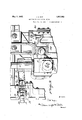
In the drawingszFigure l is a vertical sectional view through the manipulator and the drive shaft, a portion of the figure being shown in side elevation.
Fig. 2' is 'a'nenlargedi fragment'arytop plan 7 tion of a manipulator finger showing'applied thereto the retarderand accelerator unit, a portion of the view being broken away and shown. in vertical section.
Fig. 4 is a detail top plan view of the limit switch control,
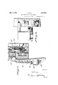
Fig. 5 is an enlarged View transverse the machine taken on the line 55 of Figure 1, a portion of the viewbeing shown in vertical section and a portion in end elevation.
A manipulator for rolling mills comprises broadly a mill-table made up of rollers upon which are deposited the ingots that are to be handled ormanipulatedand lengthwise at one side of the table there is provided a manipulator head carrying a series of fingers for engaging-and manipulating the ingot upon the table. To ena'bleapropermanipulationofthe ingots transvers'e'the table the manipulator head'is re'ciprocated in a horizontal direction.
The manipulator fingers are carried by themanipulator head together with a mechanism illustrated and wherein similar parts are des- B ignated by like reference'numerals through out the description: A general lay-out of a rolling mill manipulator appearsin Figure 1 of the drawings wherein thehead is-design'ated as an entirety; by the reference letter A; This 'headha'sas a" part ofits construction-the manipulator fin gers B and a universal drive connection or joint C which is driven by the reciprocal" drive shaft D. The drive shaft Dreciproc'at'es through and has driving connection with the: stationary motive power means E Thema nipulator head is supported upon a recipro cable carriage F which during its movement is supported upon rollers G mounted-inthe upper face of the manipulator base H upon which is suitably supported" the stationary motive power means as well'as the motorl' Describing the construction in more "detail it will be seen that the universal oirit or connection C is contained within'the chamber- 6 of a suitable housing 7 into which extends anend of a-shaft 8 which extends lengthwiseof I the table and inseparated relation'with the rollers 9 ofthe table Incidentally the rollers 9 ofthe table are driven by a beltconnection 10 with some suitable source of motive power, not shown The shaft 8 'runs lengthwise o f-the tablebut" transverse the manipulator in a position horizontally above the reciprocable carriage F and carries a plurality of finger supporting arms l1,' which'a-rms-a't their outer'end are forked and support loosely between their ends 12 and 1'3the'manipulator fingers'B."
The stationary motive power means rocks the shaft 8, as will be hereinafter described, and hence lifts and lowers the finger supporting arms 11 and consequently lifts and lowers the manipulator fingers B.
These manipulator fingers hang in a vertical position upon their pivotal support in the ends of the rocker arms and their lower ends 14 are positioned in the spaces between vertical wall 18 extending above the finger supporting rocker arms 11.
The upper face of each of these rocker arms at a point behind its forked end is provided with a vertical web 19 in separated relation with a second vertical web 20. An elongated bolt 21 passes through these webs and positioned between the web 20 and the vertical wall 18 of the finger extending end 17 is an adjusting block 22. This block 22 is held in place by the bolt 21,-the head of the bolt being counter-sunk therein.
Inasmuch as the manipulator fingers B swing freely upon their pivotal support in the ends of the rocker arm 11 it will be evident that the fingers, when lowered, can be positioned by these blocks 22. If the blocks 22 are made to engage the finger extension 17 and force the same outwardly the lower ends 14 of the manipulator fingers will be swung inwardly towards the manipulator.
The exact positioning of the lower ends of the- Downward movement of the piston in the cylinder is against the tension of acoil spring '27 and the coil spring 28 which is of a lesser size and positioned within the larger coil 27. Escapement of the piston from the upper end of the cylinder is prevented by the rod 29 the inner end of which is threadedly attached as at 30 to the piston rod while its other end is positioned exteriorly of the cylinder bottom and carries a washer or enlarged head 31. The position'of the washer or head 31 upon the rod is adj ustablethrough v the medium of the nuts 32 and 33.
This piston and cylinder constitutes a finger accelerator and retarder which might well be called a dash pot. As the fingers are lowered by the rocker arms 11 the lugs 26 of the arms engage the piston tappet and the fingers assume their lowermost position against the tension of the coil springs 27 and 28 which thus form a retarder. In assuming their lower-most position these fingers store up energy in the coil springs 27 and 28 with the result that when the fingers are lifted the energy in these springs act as an accelerator for the upward movement of the fingers. The rocker arms will of course carry the fingers down in each instance to a predetermined position which position can to some extent be adjusted by the adjusting blocks, which blocks will also hold the fingers, when down, in said predetermined adjusted positions.
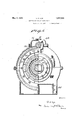
V The rear end of the housing 7 is open and rotatably mounted therein is a wheel or disc 34 having an end 35 extending through the open rear end of the housing. This portion 35 might be termed a shaft portion inasmuch as it has connection with the drive shaft D.
The drive shaft D has a rounded end portion 36 to which is bolted a spherical member' 37 having on its outer face teeth 38. Bolted to the shaft portion 35 of the wheel or disc is a cap 39 having in its end an opening 40 through which the drive shaft D passes. In its inner face this cap is provided with teeth 41 which mesh with the teeth 38 of the shafts spherical member 37 and thus a driving connection is made between the shaft D and the disc.
The spherical member 37 can rock in the cap 38, thus a self aligning connection is insured between the shaft D and the disc. End thrust of the shaft D is taken up through the engagement of the spherical member 37 with the cap 39 andengagement of the enlarged tapered head 42 with the tapered portlOIl 43 of the disc hub 35.
lVithin the spacet of the housing is a member 44 having driving connection with the-end of the shaft 8. This member 44 is open and carries transverse its opening a shaft 45. Upon the shaft 45 is mounted the universal joint or connector C. This member is free to rotate upon the shaft 45 and has an extending end provided with a ball 46 which ball is free to move within a suitable bearing'47 mounted eccentrically in the face of the wheel or disc 34.
From theparts thus. described it will be seen that when the disc or wheel 34 is refated the member-C which is in reality a pitman, will impart to the shaft 8 through the member 44 an oscillating or rocking movement which is the movement desired and necessary to cause this shaft to lift and lower the manipulator fingers through the finger. arms 11.
' It is intended that these drive parts be well lubricated and means to accomplish this lubrication are illustrated in the drawings but as the lubrication forms no part of the present invention no more than general mention will be made of the same. 7
The drive motor J is supported upon a suitable base 48 at the rear of the manipulator and is coupled as at 49 to a shaft 50 which is rotatably mounted and supported within a suitable housing 51. l/Vithin the housing this shaft 50 carries a herring-bone gear 52. The housing 51 is provided with a circular open ing-53 and the base 5 1 of the housing rests upon and is attached to the manipulator base H. The housing openings 53 are closed by suitable plates 55, which plates allow the passage of the drive shaft D.
Rotatably supported upon bearings 56 within the lower portion of the housing 51 is a drum 57 having on its exterior face a herring-bone ring gear 58 the teeth ofwhich mesh with the herringbone gt ar 52 of the motor shaft extension 50 and is consequently rotated thereby. I
lVithin the drum 57 is a. spherical shaped opening or chamber 59 within which is mounted a spherical self aligning toothed coupling 60 provided with teeth 61 having an outer curved edge which mesh with the teeth 62 whichextend inwardly from the inner face of the spherical opening 59 of the drum.
Centrally the spherical shaped toothed coupling 60 is provided with a squared opening through which extends the squared portion 63 of the drive shaft D, which shaft is elongated to extend to a point considerably in the rearof the rotary drum and the spherical toothed coupling while, as has already been described, it extends forwardly sufficiently far for driving connection with the cap 39 of the hub portion 35 of the circular wheel or disc 34.
Attention is directed to the fact that the connection between the drive shaft D andthe wheel or disc 34 is also a spherical self aligning toothed connection or coupling. The drive mechanism for the rock shaft which actuates the manipulator fingers has now been described and it will be seen that the rotary motion of the drive shaft D is converted into an oscillating motion in the finger rock shaft 8. As the manipulator head. and fingers are reciprocated transverse the rollers 9 of the table the drive shaft D will slide through the squaredopening in the self aligning toothed coupling 60 and will at all times maintain a drive connection between the shaft D and the rotary driven drum 57.
Th s sliding connection makesit possible to drive from. a stationary motive power means the manipulator fingers atany posi tion they can be made to assumeon the mill table and that for each revolution of the plate or wheel 34 and to the rotary drum 57 form supports for the drive shaft and provide a uniform bearing support for the shaft at any position and at the same time takes care of the self alignment of the shaft with the result that wear, breakage, and-upkeep 1 are materially reduced.
Conversion of a rotary motive power to oscillate a shaft as has been described consti-.
tutes a vast improvement over the manipulators ascommonly constructed in that it does away with a great many gears, links and levers which inmanipulators have heretofore been used for the reason that what constitutes the rock shaft of the present invention has in manipulators heretofore been .a rotary shaft thus necessitating links and levers to impart a lifting and lowering movement to the manipulator fingers. I
The present invention also includes a worm driven limit switch which is driven by the motor extension shaft 50. The arrangement is such that the limit switch shaft will rotate 180 degrees while the squared drive shaft D rotates 360 degrees which makes it practical to control accurately the position of the manipulator fingers when they are in their lowered positions... This limit switch is of a cam operated type and due to the fact that the limit switch shaft rotates only one-half as fast as the driving shaft a slight adjustment of the cams of the switch shaft will control accurately the stopping position of the drive shaft D when the manipulator fingers are in their lowered positions.
Having thus described my invention what I claim and desire to secure by Letters Patent is:
1. In a rolling mill manipulator, manipulatorfingers, a driven shaft, arms connecting the fingers, to, the shaft, and -means operatable by said arms for retarding and accelerating the movement "of the fingers.
'- 2. In a rolling mill manipulator, manipurock shaft, a plurality of rock arms support ed-and actuated thereby, manipulator fingers supported and actuated by said rock arms, dash pots positioned beneath each of said rock arms, said dash pots comprising a cylinder having ,therein reciprocable pistons, springs positioned beneath said pistons, said rockarms adapted to engage said pistons when lowering themanipulator fingers and to depress the pistons against spring tension normally holding them upward, and said pistons by reason of the stored energy in said springs accelerating the movement of the rock arms and the manipulator fingers when the same are raised.
4. In a rolling mill manipulator having manipulator fingers, a driven rock shaft, a plurality of rock arms attached to said shaft, said rock arms loosely pivotally supporting the manipulator fingers, said rock arms carrying adjustable blocks adapted to engage said fingers and move them upon their pivotal support to position the fingers when in their lowered positions.
5. Arolling mill manipulator comprising a driven rock'shaft having attached thereto a plurality of rock arms having bifurcated outer ends, manipulator fingers pivotally supported in the bifurcated ends of "the rock arms and free to swing therein, adjustable blocks movably supported in the bifurcated ends of the rock arms and adapted for engagement with the manipulator fingers, and means to move said blocks into and out of engagement with the manipulator fingers for positioning the same when in their lowered positions. V I
6. A rolling mill manipulator comprising a driven rock shaft, a plurality of rock arms carried by said shaft and pivotally supporting manipulator fingers, said fingers free to swing upon their pivotal support and adapted to be raised and lowered by the rock arms and said rock shaft, means carried by said rock arms for positioning the fingers when in their lowered positions, and means independent of the drive means of the fingers for retarding the movement of the rock arms as the same assume positions to lower the fingers, and said retarding means accelerating the movement of the rock arms andthe fingers when the rock arms are lifted to raise the fingers.
e 7. A construction such as that defined in I claim 6, wherein the mechanism defined is supported upon a carriage reciprocable in a horizontal plane to permit the movement of to raise and lower said fingers, means carried by said rock'arms for positioning. the fingers when in their lowered positions, means positioned beneath said rock arms for retarding the movement of the same in a downwardly direction and accelerating the movement of the same in an upwardly direction, a driving connection between the rock shaft and the stationary motor, said driving connection converting the rotary motive power ofthestationary motor into a rocking motion to said rock shaft, and said drive connection between the rock shaft and the stationary motor permitting movement of the rock shaft towards and away from the motor but constantly .maintaining driving connection with the rock shaft and the motor.
9. In a rolling mill manipulator, manipulator fingers, a drive therefor, and a retarding device operable upon the movement of the fingers and retarding the downward movement thereof.
10. In a rolling mill manipulator, manipulator fingers, a drive therefor, and a combined retarding and accelerating device acting on the fingers and slowing the downward movement and accelerating the upward movement thereof.
11. In a rolling mill manipulator, manipulator fingers, a drive therefor, a combined finger retarding and accelerating device, and said device operated by and acting'on the finger drive.
12. In a rolling mill manipulator, manipulator fingers, a drive therefor, and a resilient retarding device operatable on the fingers and controlling the downward movement thereof.
18. In a rolling mill manipulator, manipulator fingers, a' drive therefor, and a resilient combined retarding and accelerating device operated upon -the movement of the fipgers and controlling the movement there- 0 r 14. In a rolling mill manipulator, pivotally mounted driven manipulator fingers, for lifting and lowering the same, a drive, and movable means engaging said fingers for adjusting the positions of the fingers when in their lowered positions.
15. In a rolling mill manipulator, pivotally mounted manipulator fingers, a drive for lifting and lowering the same, and movable means for engaging said fingers above their pivotal support to adjust the position of the fingers when in their lowered positions.
16. In a rolling mill manipulator, movable fingers, a drive therefor, finger supporting elements, and movable means carried by said supporting elements for adjusting the position of the fingers when in their lowered positions.
17. In a rolling mill manipulator, manipulator fingers, a drive mechanism supporting the finger arms connecting the fingers to the mechanism, and means positioned beneath said arms and operable thereby for retarding and accelerating the movement of the fingers.
18. In a rolling mill manipulator, manipulator fingers, a drivenshaft, arms connecting the fingers to said shaft, resilient means positioned below each finger supporting arm, and said resilient means retarding the downward movement of the arms and fingers and accelerating their upward movement.
19. A rolling mill manipulator comprising a shaft, a plurality of arms supported and actuated thereby, manipulator fingers supported and actuated by said arms, dash pots positioned beneath said arms, and said dash pots comprising a cylinder having therein a piston movable against and compressing a resilient element, said dash pots being actuated by said arms for retarding and accelerating the movement of said fingers on their downward and upward movements respectively.
20. A rolling mill manipulator comprising manipulator fingers, a drive mechanism including a plurality of finger supporting elements having bifurcated outer ends, said manipulator fingers pivotally supported in the bifurcated ends of said supporting elements and free to swing therein, adjustable means positioned in the bifurcated ends of said elements and adapted for engagement with the manipulator fingers, and means to move said a-dj' ustable means towards and away from said manipulator fingers for positioning the same when in their lowered positions.
In testimony whereof I hereunto afiix my signature.
RALPH D. NYE.
Priority Applications (1)
| Application Number | Priority Date | Filing Date | Title |
|---|---|---|---|
| US487280A US1857063A (en) | 1930-10-08 | 1930-10-08 | Manipulator for rolling mills |
Applications Claiming Priority (1)
| Application Number | Priority Date | Filing Date | Title |
|---|---|---|---|
| US487280A US1857063A (en) | 1930-10-08 | 1930-10-08 | Manipulator for rolling mills |
Publications (1)
| Publication Number | Publication Date |
|---|---|
| US1857063A true US1857063A (en) | 1932-05-03 |
Family
ID=23935092
Family Applications (1)
| Application Number | Title | Priority Date | Filing Date |
|---|---|---|---|
| US487280A Expired - Lifetime US1857063A (en) | 1930-10-08 | 1930-10-08 | Manipulator for rolling mills |
Country Status (1)
| Country | Link |
|---|---|
| US (1) | US1857063A (en) |
-
1930
- 1930-10-08 US US487280A patent/US1857063A/en not_active Expired - Lifetime
Similar Documents
| Publication | Publication Date | Title |
|---|---|---|
| GB1405774A (en) | Apparatus for the stepwise feed of workpieces | |
| US1857063A (en) | Manipulator for rolling mills | |
| US1969433A (en) | Flying shear | |
| US3772986A (en) | Mechanical double action press using a link mechanism | |
| US2550063A (en) | High-speed metal drawing press | |
| US2086835A (en) | Power transmitting mechanism | |
| US2232889A (en) | High-speed forging press | |
| US1684617A (en) | Flying shears | |
| US1982603A (en) | Eccentric control | |
| US2235047A (en) | Adjustable geneva mechanism | |
| US2079360A (en) | Drive mechanism for shaker conveyers | |
| US2753937A (en) | Lever-operated shears | |
| US2321061A (en) | Valve gear | |
| GB272660A (en) | Improvements in or relating to means for converting reciprocating motion into rotarymotion and vice versa | |
| US2023554A (en) | Counterweight mechanism for oil well pumps | |
| US1340405A (en) | Steam-engine valve-gear | |
| US1071793A (en) | Valve-gear. | |
| GB664549A (en) | Improvements in and relating to dough handling machines | |
| US2273173A (en) | Motion-transmitting mechanism | |
| US1705138A (en) | Valve mechanism | |
| DE479494C (en) | Reversing device for locomotives | |
| US1757841A (en) | Valve and regulating movement for engines | |
| US2890608A (en) | Safety mechanism for a draw rolling mill | |
| US2693157A (en) | High speed triple action press | |
| US5129A (en) | Operating cut-gee valves |