US1857060A - Electric welder - Google Patents
Electric welder Download PDFInfo
- Publication number
- US1857060A US1857060A US267605A US26760528A US1857060A US 1857060 A US1857060 A US 1857060A US 267605 A US267605 A US 267605A US 26760528 A US26760528 A US 26760528A US 1857060 A US1857060 A US 1857060A
- Authority
- US
- United States
- Prior art keywords
- units
- cam
- clamp
- edges
- machine
- Prior art date
- Legal status (The legal status is an assumption and is not a legal conclusion. Google has not performed a legal analysis and makes no representation as to the accuracy of the status listed.)
- Expired - Lifetime
Links
- 238000003466 welding Methods 0.000 description 26
- 239000002184 metal Substances 0.000 description 22
- 230000007246 mechanism Effects 0.000 description 16
- 238000005266 casting Methods 0.000 description 15
- 238000010276 construction Methods 0.000 description 14
- 238000000034 method Methods 0.000 description 7
- 230000008093 supporting effect Effects 0.000 description 7
- 230000000994 depressogenic effect Effects 0.000 description 5
- 238000010438 heat treatment Methods 0.000 description 5
- 230000000153 supplemental effect Effects 0.000 description 4
- 208000027418 Wounds and injury Diseases 0.000 description 3
- 230000006378 damage Effects 0.000 description 3
- 230000001419 dependent effect Effects 0.000 description 3
- 230000000694 effects Effects 0.000 description 3
- 208000014674 injury Diseases 0.000 description 3
- 101001005711 Homo sapiens MARVEL domain-containing protein 2 Proteins 0.000 description 1
- 230000001133 acceleration Effects 0.000 description 1
- HSFWRNGVRCDJHI-UHFFFAOYSA-N alpha-acetylene Natural products C#C HSFWRNGVRCDJHI-UHFFFAOYSA-N 0.000 description 1
- 238000002788 crimping Methods 0.000 description 1
- 238000005520 cutting process Methods 0.000 description 1
- 125000002534 ethynyl group Chemical group [H]C#C* 0.000 description 1
- 230000008014 freezing Effects 0.000 description 1
- 238000007710 freezing Methods 0.000 description 1
- 238000005304 joining Methods 0.000 description 1
- 238000004519 manufacturing process Methods 0.000 description 1
- 230000008018 melting Effects 0.000 description 1
- 238000002844 melting Methods 0.000 description 1
- 229920000136 polysorbate Polymers 0.000 description 1
- 239000011435 rock Substances 0.000 description 1
- 238000005493 welding type Methods 0.000 description 1
Images


Classifications
-
- B—PERFORMING OPERATIONS; TRANSPORTING
- B23—MACHINE TOOLS; METAL-WORKING NOT OTHERWISE PROVIDED FOR
- B23K—SOLDERING OR UNSOLDERING; WELDING; CLADDING OR PLATING BY SOLDERING OR WELDING; CUTTING BY APPLYING HEAT LOCALLY, e.g. FLAME CUTTING; WORKING BY LASER BEAM
- B23K11/00—Resistance welding; Severing by resistance heating
- B23K11/04—Flash butt welding
Definitions
- This invention relates to improvements in electric welders and is directed more particularly to an electric welding apparatus of the so-called flash type of welder, and is particularly designed and adapted to the Welding together of the side and back portions of a metal automobile body.
- the body In the manufacture of automobile bodies it is essential that the body be made of a plum rality of pieces.
- a metal body In a metal body the rear ends of the sides of the body are united to the outer edges of the body back.
- the meeting edges of the sides and back are of considerable length, often being more than fifty [5 inches throughout the length of the abutting edges.
- a gas or an acetylene weld Up until the present time it has been usually customary to unite the sides and backs of bodies by a gas or an acetylene weld. This method of uniting the parts together is quite expensive because it is slow and additionally is objectionable because it requires highly experienced operators to make a successful job.
- Electric welding is not new and has been i thought of before in connection with the uniting of automobile metal body portions, but so far as I am aware, no one has been able to devise or discover a machinewhich .will operate successfully- 0 After extended experimentation, tests and the expenditure of a large amount of both time and money, I have devised a welding machine which is highly eificient in the welding together of automobile body parts.
- the metal will burn out at its point of engagement before the remote point has been brought to a welding temperature.
- the primary object of the present invention is the provision of an electric welding machine for welding the metal parts composing an automobile body together, which is to a very large extent automatic in its operation.
- Another and further objectof the invention is the provision of a novel construction of combined toggle and clamping means for clamping the body parts to theelectrodes.
- a further object of the invention is the provision of an equalizing connection between the clamping and actuating mechanisms at the opposite sides of the clamps for assuring an equal pressure upon the clamps throughout their entire length.
- Another and further object of the invention is the provision of a machine of the character described which is built intwo units, 7
- both of which are so mounted as to have an almost universal adjustment whereby the two units can be so set as to operate upon autor'nobilebodies of different shapes and contours.
- a still further object of the invention is the provision of a novel control means for starting the operation of the machine and automatically controlling the operation of the machine throughout one cycle of operation.
- a still further object of the invention is the discovery of a new method and a novel machine for carrying out the method in respect to the welding together of automobile metal body parts.
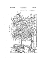
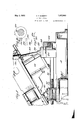
- Figure 1 is a view in side elevation showing a complete machine comprising two units, a portion of one unit being broken away.
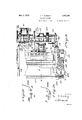
- Figure 2' is a top plan view taken on the line 2-2 of Figure 1.
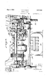
- Figure 3 is a rear view of one of the units making up the machine.
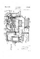
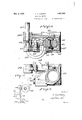
- Figure 4 is a longitudinal vertical sectional view taken on the line 4-4 of Figure 2.
- Figure 5 is a view in side elevation illustrating the manner in which one of the units is adjustably supported, a'proportion of the view being shown in vertical section.
- Figure 6 is a transverse vertical sectional view taken on the line 6-6 of Figure 1
- Figure 7 is an enlarged side view illustrating the clamp operating toggle and equalizing bar, a portion of the view being broken away and shown in vertical section.
- Figure 8 is a horizontal sectional view taken on the line 8-8 of Figure 7 looking in the direction indicated by arrow.
- Figure 9 is a top plan view of Figure 8.
- Figure 10 is a detail perspective view of the casting carrying the toggle operating mechanism and the slide bar carrying the movable electrode of one of the units.
- Figure 11 is a top plan view of Figure lO.
- Figure 12 is an enlarged perspective view showing the automatic starting, stopping and controlling mechanism for one of the units.
- Figure 13 is 'an enlarged detail side view of a modified form of tog le for operating the clamps of one unit of the machine, a portion being broken away and shown in vertical section.
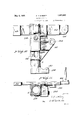
- Figure 14 is a diagrammatic view illustrating the manner in which the automobile body back and side portions are clamped upon the stationary and movable electrodes.
- Figure 15 is a diagrammatic View illustrating the position assumed by the vehicle body tion and operation and in the description of back and side portions at the time they are upset and the actual welding of the parts takes place.
- Figure 16 is a diagrammatic view of the automatically operated switchfor' controlling the transformer circuit.
- Figure 17 is a diagrammatic view of the automatically operated switch for controllingthe driving motor circuit.
- a base A upon which is suitably mounted two welding units making up the machine, these units being designated by letters B and C, lVith reference to Figure 1, B represents the left hand unit and C the rigll lltlz-hand unit.
- the toggle mechanism for the fixed electrode clamp is designated at F and the toggle for the movable electrode clamp is designated at G.
- the shaft 23, in the gear reduction box, carries a gear 24 meshing with a ear 25 carried upon the shaft 26 which sha t at its outer end carries the cams 27
- the cams 27 are for the purposeof driving or moving the movable electrodes of the units downwardly or inwardly towards the fixed electrodes, causing the adjacent edges of the vehicle body parts to'be brought into abutment.
- a cylinder K provided with a suitable piston is provided and through the medium of air pressure against the piston of this cylinder, the mova le electrode is carried back to its elevated the machine.
- a combined starting, controllin and stopping mechanism is illustrated in igures 12, 16 and 17 of the drawings and is designated entirely by L.
- Figures 14 and 15 illustrate back and side portions of the vehicle body.
- the back portion carries the numeral 1000and the side portion the numeral 2000.
- the body back portion of the vehicle is supported upon and between the two fixed electrodes of the two units, while the ones constituting the body side portions are sup ported upon the movable electrodes of each position after each operation of sential features of the invention in a broad manner and a detailed description of the component parts of the machine, the operation of the machine and the method practiced bythe machine will now be given.
- the two units can be moved towards and away from each other through the medium of the elongated screw 28 and the ratchet jack 29,which is mounted upon the base A intermediate the two units.
- the screw 28 passes through the blocks 30 which support the front ends of the units and which are slidable upon the base.
- the two units can be pulled towards one another as the blocks .30 at the front end of the machine are connected by a suitable framework 31 to the transverse supporting members or blocks 32 at the rear ends of the units which are also slidable upon the base A.
- the blocks 80 at the front ends of the units carry removable caps 33 the upper faces of which are shaped to receive the ball shaped members 34 which are in turn attached to the under side of the front ends of the units.
- This construction gives the front ends of the units a universal support which unables the front ends of the units to be moved into any desirable position upon the supporting cap.
- the rear ends of the units are supported upon externally threaded arms 35, the lower ends of which are pivotally supported as at 36 in bearings 37 mounted upon the upper face of the transverse member 32 while the upper ends pass, through suitable turn-buckles 38. It will be understood that there is an arm at each side of the machine and that through this construction the rear ends of the units can be raised and lowered as described.
- the bearing-37 is bolted to a transverse slide member 39 and through the medium of a suitable transversely extending screw 40 the rear ends of the units can be moved transverse the base the front ends of the units swinging on the swivel ball or universal support 34.
- the units have awide degree of adjustment in respect. to one another which makes it possible for the machine to be adjusted to operate upon jobs or work of diversified characters.
- a jig 41 spans the space between the two units and is for the purpose of supporting the automobile body back 1000 in place with the vertical edges of the back extending slightly beyond the fixed electrodes D while vertical jigs 42 and 42* are for the purpose of supporting the sides of the automobile body in place upon the movable electrodes E with the vertical edges of the sides extending forwardly beyond the electrodes.
- each unit Extending throughout the length at each side of each unit is a slide 43 which passes /through and is held in place by suitable front guides .44 and rear guides 45. At the inner sides of their rear ends these slides carry cam rollers 46 which are engaged by the cams 27 carried at the outer ends oi the cam shaft 26.
- clamps E for the movable electrodes are bars extending entirely transverse the unit above the electrode and that at one end this bar clamp is pivotally supported and attached to the plunger 49 as at 50 while at the other end a swinging lock 51 is provided.
- the lock 51 is pivotally attached and supported upon the upper end of the plunger-49 as at 52 and the lock is provided with an opening to receive and hold the outer end 53 of the clamp.
- the lower face of the clamp bar is provided with a detachable die 54 which cooperates with the removable die 55 carried by the movable electrode E so that when the clamp is in place the vertical edge of the vehicle body side portion 2000 is clamped firmly in place to be movable with the electrode.
- the clamp bars are very heavy, inasmuch as 20 to 50 tons pressure is applied to themand as they are manipulated manually they are provided with an eye '56 to which it is intended to attach a cable extending over a Toggle mechanism.
- the mechanism for operating and applying the pressure to the clamps comprises the cylinder 48 which carries a suitable piston having an upwardly extending elongated piston rod 57.
- air pressure can be delivered to either the upper or lower sides of the piston.
- the upper end attached to the pin or stub shaft 67 carried by the lower end of the plunger 4.9 which plunger incidentally has a lower cylinder like portion 49 which slides in the lower end of the casting 47.
- This stub shaft extends outwardly through the elongated opening 69 in the casting 47 and is slidable therein when the plunger reciprocates.
- The'frec end of the link is pivotally connected to the stub shaft 68 which is rigidly supported in the openings 119 adjacent the upper end of the casting 4L7.
- the stub shaft 68 passes through an elongated opening in the upperend of the plunger 49 to permit reciprocation of the plunger in respect to the stub shaft 68.
- the plungers 49 and 49 are integral and reciprocate together.
- the equalizing bar is an important feature of this construction as it is absolutely essential to clamp the vertical body portions equally throughoutthe length of the dies to prevent any crimping, buckling or pulling of the metal. If the equalizing bar is elimi;
- the ,valves, which are manually operated, for controlling the delivery of air to thecylinders 48 for the rear or movable electrode toggle mechanism is designated at 73 of Figure 1 and the valve for the cylinders 74 of the fixed electrode toggle clamp is designated at 7 5.
- the equalizing bar effects a very great saving in the dies from the standpoint of wear or injury.
- a set of dies is quite expensive and the saving of wear and injury to the dies is important from the standpoint of economical operation of the machine.
- a switch (not shown) is also provided for turning on the current to the transformer when either of the units is to be operated.
- the shape of the cam 27 (see Figure ,4) is such that the high portion 80 of the cam reaches'the cam roller 43 at a time just before the edges of the back portion of the body clamped in position upon the fixed electrode dies are abutted by the adjacent edge of the body side portion which is clamped upon the movable electrode.
- the high portion 80 of the cam engages the cam roller the slide is given a final sudden kick forward and this final kick causes the edges of the back and body portion to come into abutment and to be slightly upset, as appears in Figure 15 of the drawings.
- This upsetting and abutting of the metal edges of the body portion is maintained together with the application of the electric welding current for a short period of time and causes a further heating of the metal which causes a perfect weld of great strength. throughout the length of the abutting edges of thesheets.
- a general sup porting bracket 81 which is suitably attached to a rear portion 82 of the unit.
- a shaft 83 is rotatably supported upon the upper end of this bracket and extends outwardly through a suitable bearing 84 (see Figure 3) and carries on its outer end the control handle 78.
- the inner end of this shaft carries a. fixed arm 85 having pivotal connection at 86 with a downwardly extending rod 87, the lower end of which is provided with a pivotal supported link 87 carrying in its end a cam or wedge 88 positioned between the ends 89 and 90 of the internal brake 79.
- This internal brake ismade in two pieces 91 and 92 pivend of the spring is adjustably connected through the medium of a screw 97 passing through a threaded o ening 98 which in turn s an integralpart o' the arm 85 and exerts a normal outward and upward pull upon the rod 87.
- This normal outward and upward pull upon the rod 97 would tend to apply the brake but is prevented from doing so through the medium of the lock bar 99.
- This lock bar is pivotally supported at 100 upon the upper end of the bracket 81 and has in its lower end an L-shaped cut out portion 101 which engages the pin 102 carried adjacent the upper end of the rod 87 and is held normally 1n engagement with that pin through the medium of the spring tension of the coil spring 103.
- the cam shaft 26 carries a supplemental cam 104 upon which is pivotally mounted a trigger 105 adapted to engage the lower end 106 of the lock bar 99 when the cam shaft 26 is rotated.
- FIGS 16 and 17 diagrammatically illustrate the manner of automatically controlling the current delivered to the driving motor and the transformer.
- the main cam-shaft 26 carries a cam 500 having a low spot or depression 501.
- a switch arm 502 is pivotally mounted upon a bracket 503 attached to the face 82 of the unit and positions the switch arm 502 between the camshaft 26 and the face of the unit.
- the transformer circuit 504 is shown broken as theroller 505, at the upper end of the switch arm, is in the depression 501, thus permitting the spring 506 to start the contact members 507 and 509.
- a switch arm 510 is pivotally supported upon a bracket 511 having attachment to the unit face 82. At its lower ends this switch arm carries a contact member 512 for making and breaking the circuit through the contact member 513. At its upper end the switch arm carries a roller 514, which engages a cam 515 carried by the shaft 83, which. shaft is oscillated by the control handle 78. In this figure of the drawings the handle 78 is shown in its upper position and the motor'circuit 513 by the spring 517.
- the supplemental cam 104 releases the control handle 78 and allows it to return to the position shown in Fig. 17 of the drawings, thus automatically cutting off the current to the driving motor and the cam 500 is so positioned on the cam shaft 26 that it has operated to open the transformer circuit, as illustrated in Fig. 16 of the drawings.
- Movable electrode return cylinder As has been previously described, the movable electrode together with its clamp, is driven forwardly or downwardly by the cams 27. After a complete cycle of operation the movable electrode is in its forward or lower position and to return this electrode to its rear position to enable the placi'ng'of another piece of work in the machine for o eration there is provided anair cylinder which appears more clearly in Figures 1, 2 .and 4 of the drawings.
- This cylinder is bolted in place as clearly appears at 110 where it will be seen that the cylinder is supported u on the cross member 111 which cross mem er is fixed to a nonmovable part of the machine.
- Air is delivered into this cylinder by a suitable hose 112 from any convenient source of supply and tends to drive the piston in the cylinder rearwardly.
- a U-shaped frame 113 has its two ends connected to a shaft 114 which shaft in turn is carried by a bracket 115 at. tached to the machine portion 116 which moves with the movable electrode.
- the rear of the U comprisesabar 117 which extends across the rear of the cylinder K and is engaged by a protruding part of the cylinder piston.
- each lock has 1on bearing supports 118 so that the locks are adequately supported to withstand hard usage and at the same time remain in perfectbalinement to receive the ends 53 of the ars.
- castings are provided with extensions 120 for pivotally supporting at 121' the cylinders 48 and 74 for operating the toggles as well 'as providing a bracket in which is a bearing 122 for supporting the ends of the equalizing shaft or bar 61.
- the dies 54 and 55 which are carried by the clamp bars and electrodes respectively, are made to fit one another very accurately as has been described, so that the metal of the body portion which they clamp will not be buckled orpulled at any point.
- This toggle feature is also essential to prevent injury to the dies.
- the machine is capable for operation upon work of different shapes position which in effect locks the clamp in clamped position and holds the clamps in their position irrespective of. whether or not air pressure is maintained below the cylinder piston.
- the motor 77 for driving the machine can be either a direct or alternating current motor in accordance with the type of electric current which is at hand for use.
- the links 203 and 205 are in a suitable casting 206 in which reciprocates a slide 207 upon the upper end of which is pivotallysupported the lock 51.
- the upper link to the toggle is pivotally attached as at 208 to the casting 206 and the lower link 205 of the block 207* which is attached to the lower end of the slide 207 by bolts 211 passing through the elongated opening 210.
- the bolt 210 coming up directly under the block if it is found desirable to apply a little more pressure to the welding jaws or to adjust the jaws for greater or less opening, the bolts 211 are loosened and the adjusting screw is turned up or down thus slightly raising or lowering the block 210 which" will bring about the desired adjustment of the welding jaws or dies.
- the cylinder 200 is swivelly mounted upon the trunnion 2.00 in the casting part 200 which is firmly and rigidly secured to the casting 206 by suitable bolts 212.
- the next operation is to deliverair to the cylinders 74 which operate the toggles for pulling down the clamp bars above the two stationary electrodes of the two units. Air is thereafter delivered to the cylinders 64 for causing the-clamp bars of the movable electrodes to firmly clamp the lower ends of the vehicle body side portions in place.
- the construction of the dies and the jigs is such that these vehicle body parts can be rapidly and easily placed upon the two units and the clamping effected in a very short period of time and due to the equalizin bars joining the toggle mechanism at the opposite sides of the units the metal between 'the dies of the electrodes and the clamps is not caused to buckle or bepulled which would cause a bad weld and 'at the same time injure the dies.
- the arrangement and construction is also such that the edges of the vehicle side body portions are in perfect alinement with the edges of the vehicle body back portion.
- each unit is to be 0 erated separately rather than to operate t e units simultaneously, although it has been explained that the two units can be operated simultaneously, if desired.
- edges of the vehicle body back and side portions have approached each other soclosely as to cause them to lightly engage at different points therethrough their lengths and the electric current flashes be tween these. edges and causes an intense heat- "ing of the' protruding edges of these body portions.
- This is a natural result as the fixed and movable electrodes are in the transformer circuit and the circuit is open until the current flashes between the body portions or until the edges of the body portion actually abut.
- the forward final kick movement of the movable electrode is very rapid and causes the edges of the body portions to come into abutment and to be upset in the lie" manner diagrammatically illustrated in Figure 15 of the drawings.
- the pressure of kick is four or five thousand pounds and as the metal at the edges of the body portions have been intensely heated, it causes these edges to upset when they come into abutment, and to bring about a homogeneous electric weld throughout the length of the abutting edges of these portions,
- the continued application of the welding current during this upsetting period assures a strong weld as the heating of the metal is continued for a short period after the application of pressure with the result that all pin holes in the metal are closed.
- the abutting edges of the body portions are of a length in excess of fifty inches, Insofar as I am aware an instantaneous flash weld.
- the projecting sheets is slow, it will result in the burning away of the sheet and the flashes of the current will be of a hrightlight, but it will not generate the heat necessary to make a proper weld, while if you have too Consequently the actual construction of the actuating cam is dependent upon the transformer capacity and the speed at which the actuating cams are rotated.
- the supplemental cam 500 carried by t is cam shaft'is'so timed with relation to the cam shaft and the switch that it operates the switch at the instant the final kich" movemachine to accomplish a weld at the opposite edge of the body back portion,
Landscapes
- Engineering & Computer Science (AREA)
- Mechanical Engineering (AREA)
- Resistance Welding (AREA)
Description
F. P. M BERTY ELECTRIC WELDER May 3, 1932.
Filed April 5, 1928 ll Sheets-Sheet l May 3, 1932. MGBERTY 1,857,060
ELECTR I C WELDER Filed April 5, 1928 11 Sheets-Sheet 2 & $3
May 3, 1932. F. P. MCBERTY 1,857,060
ELECTRI C WELDER Filed April 5, 1928 11 Sheets-Sheet s May 3, 1932.,
F. P. MCBERTY ELECTRIC WELDER Filed April 5, 1928 11 Sheets-Sheet 4 May 3, 1932 F. M BERTY ELECTRIC WELDER Filed April 5 1928 l l Sheets-Sheet 5 F P. M BERTY May 3, 1932.
ELEG TRIC WELDER Filed April 5, 1928 ll Sheets-Sheet 6 F. P. MGBERTY May 3, 1932.
ELECTRI C WELDER Filed April 5, 1928 ll Sheets-Sheet fl /15, aAeRAmQMZM y 3, 1932- F. P. M BERTY ,8
ELECTRIC WELDER Filed April 5, 1928 11 Sheets-Sheet 8 i 64 l g 429 W I s X m1- ili MUD -41- Q90 May 3, 1932. MCBERTY 1 1,857,060
ELECTRIC WELDER Filed April 5, 1928 11 Sheets-Sheet 9 2 4 3 WIU May 3, 1932. F. P, MCBERTY 1,857,060
ELECTRIC WELDER Filed April 5, 1928 11 Sheets-Sheet 10 gnucmhw F. P. M BERTY May 3, 1932.
ELECTRI C WELDER Filed April 5, 1928 11 Sheets-Sheet ll l I l I I l II Patented May 3, 1932 FRED I. MCIBERTY, OF WARREN, OHIO ELECTRIC WELDER Application filed April 5,
This invention relates to improvements in electric welders and is directed more particularly to an electric welding apparatus of the so-called flash type of welder, and is particularly designed and adapted to the Welding together of the side and back portions of a metal automobile body.
In the manufacture of automobile bodies it is essential that the body be made of a plum rality of pieces. In a metal body the rear ends of the sides of the body are united to the outer edges of the body back. The meeting edges of the sides and back are of considerable length, often being more than fifty [5 inches throughout the length of the abutting edges. Up until the present time it has been usually customary to unite the sides and backs of bodies by a gas or an acetylene weld. This method of uniting the parts together is quite expensive because it is slow and additionally is objectionable because it requires highly experienced operators to make a successful job.
Electric welding is not new and has been i thought of before in connection with the uniting of automobile metal body portions, but so far as I am aware, no one has been able to devise or discover a machinewhich .will operate successfully- 0 After extended experimentation, tests and the expenditure of a large amount of both time and money, I have devised a welding machine which is highly eificient in the welding together of automobile body parts.
5 i In the welding art it has been difiicult to make a successful weld when the joint abutment is of considerable length. In making a weld of considerable len h the difiiculty has been in bringing the e ges of the pieces to be united together in alinement. An exact alinement is essential to prevent the burning out of the metal. If the pieces engage or abut at one point in the length of the weld before. they meet at some other remote point,
5 the metal will burn out at its point of engagement before the remote point has been brought to a welding temperature.
Great difliculty has also been experienced by reason of the fact that the weld, when completed, must be sufliciently strong towith- 1928. Serial No. 267,605.
of the operation to make it a commercial success.
()ther difiiculties experienced in respect to electric welding machines for work of this character will be pointed out in the following detailed description of the invention.
The primary object of the present invention is the provision of an electric welding machine for welding the metal parts composing an automobile body together, which is to a very large extent automatic in its operation.
Another and further objectof the invention is the provision of a novel construction of combined toggle and clamping means for clamping the body parts to theelectrodes.
A further object of the invention is the provision of an equalizing connection between the clamping and actuating mechanisms at the opposite sides of the clamps for assuring an equal pressure upon the clamps throughout their entire length.
Another and further object of the invention is the provision of a machine of the character described which is built intwo units, 7
both of which are so mounted as to have an almost universal adjustment whereby the two units can be so set as to operate upon autor'nobilebodies of different shapes and contours.
A still further object of the invention isthe provision of a novel control means for starting the operation of the machine and automatically controlling the operation of the machine throughout one cycle of operation.
A still further object of the invention is the discovery of a new method and a novel machine for carrying out the method in respect to the welding together of automobile metal body parts.
Other further objects of the invention and novel features of construction of both the machine and the method practiced thereby,
will be more specifically pointed out in the following drawings.
In the drawings: Figure 1 is a view in side elevation showing a complete machine comprising two units, a portion of one unit being broken away.
Figure 2'is a top plan view taken on the line 2-2 of Figure 1.
Figure 3 is a rear view of one of the units making up the machine.
Figure 4 is a longitudinal vertical sectional view taken on the line 4-4 of Figure 2.
Figure 5 is a view in side elevation illustrating the manner in which one of the units is adjustably supported, a'proportion of the view being shown in vertical section.
Figure 6 is a transverse vertical sectional view taken on the line 6-6 of Figure 1 Figure 7 is an enlarged side view illustrating the clamp operating toggle and equalizing bar, a portion of the view being broken away and shown in vertical section.
Figure 8 is a horizontal sectional view taken on the line 8-8 of Figure 7 looking in the direction indicated by arrow.
Figure 9 is a top plan view of Figure 8.
Figure 10 is a detail perspective view of the casting carrying the toggle operating mechanism and the slide bar carrying the movable electrode of one of the units.
Figure 11 is a top plan view of Figure lO.
Figure 12 is an enlarged perspective view showing the automatic starting, stopping and controlling mechanism for one of the units.
Figure 13 is 'an enlarged detail side view of a modified form of tog le for operating the clamps of one unit of the machine, a portion being broken away and shown in vertical section.
Figure 14 is a diagrammatic view illustrating the manner in which the automobile body back and side portions are clamped upon the stationary and movable electrodes.
Figure 15 is a diagrammatic View illustrating the position assumed by the vehicle body tion and operation and in the description of back and side portions at the time they are upset and the actual welding of the parts takes place.
Figure 16 is a diagrammatic view of the automatically operated switchfor' controlling the transformer circuit.
Figure 17 is a diagrammatic view of the automatically operated switch for controllingthe driving motor circuit.
Describing the invention in broad terms, there is provided a base A upon which is suitably mounted two welding units making up the machine, these units being designated by letters B and C, lVith reference to Figure 1, B represents the left hand unit and C the rigll lltlz-hand unit.
ese two units are identical in construcdescription and accompanying These clamps are for the purpose of clampi ing the edges of the automobile body parts which are placed upon the machine for the purpose of welding them into a single structure.
The toggle mechanism for the fixed electrode clamp is designated at F and the toggle for the movable electrode clamp is designated at G.
There is a source of electric current supply (not shown) for the supply of current to the driving motor 77 mounted upon the rear end of each of the units, and this operating motor is for the purpose of driving the motor shaft 20 which in turn drives the gears in the gear reduction box 21 through the medium of a driving chain 22 which interconnects the motor shaft 20 and the shaft 23 which terminates in the gear reduction box.
The shaft 23, in the gear reduction box, carries a gear 24 meshing with a ear 25 carried upon the shaft 26 which sha t at its outer end carries the cams 27 The cams 27 are for the purposeof driving or moving the movable electrodes of the units downwardly or inwardly towards the fixed electrodes, causing the adjacent edges of the vehicle body parts to'be brought into abutment.
A cylinder K provided with a suitable piston is provided and through the medium of air pressure against the piston of this cylinder, the mova le electrode is carried back to its elevated the machine.
A combined starting, controllin and stopping mechanism is illustrated in igures 12, 16 and 17 of the drawings and is designated entirely by L.
Figures 14 and 15 illustrate back and side portions of the vehicle body. The back portion carries the numeral 1000and the side portion the numeral 2000.
The body back portion of the vehicle is supported upon and between the two fixed electrodes of the two units, while the ones constituting the body side portions are sup ported upon the movable electrodes of each position after each operation of sential features of the invention in a broad manner and a detailed description of the component parts of the machine, the operation of the machine and the method practiced bythe machine will now be given.
In reading and considering the following description of the machine and its parts it will be realized that departures from the actual and specific construction shown can be made without departing from the spirit of the invention as set forth in the accompanying claims.
In carrying out the invention and method it is first necessary to adjust the two welding machines or units properly in respect to one another so that they can operate upon the particular work to be done.
The two units can be moved towards and away from each other through the medium of the elongated screw 28 and the ratchet jack 29,which is mounted upon the base A intermediate the two units. The screw 28 passes through the blocks 30 which support the front ends of the units and which are slidable upon the base. By operating the jack the two units can be pulled towards one another as the blocks .30 at the front end of the machine are connected by a suitable framework 31 to the transverse supporting members or blocks 32 at the rear ends of the units which are also slidable upon the base A. s
The blocks 80 at the front ends of the units carry removable caps 33 the upper faces of which are shaped to receive the ball shaped members 34 which are in turn attached to the under side of the front ends of the units. This construction gives the front ends of the units a universal support which unables the front ends of the units to be moved into any desirable position upon the supporting cap.
The rear ends of the units are supported upon externally threaded arms 35, the lower ends of which are pivotally supported as at 36 in bearings 37 mounted upon the upper face of the transverse member 32 while the upper ends pass, through suitable turn-buckles 38. It will be understood that there is an arm at each side of the machine and that through this construction the rear ends of the units can be raised and lowered as described.
The bearing-37 is bolted to a transverse slide member 39 and through the medium of a suitable transversely extending screw 40 the rear ends of the units can be moved transverse the base the front ends of the units swinging on the swivel ball or universal support 34. v a
Through the arrangement of support described, it will be seen that the units have awide degree of adjustment in respect. to one another which makes it possible for the machine to be adjusted to operate upon jobs or work of diversified characters.
As the machine is primarily designed to weld the back and sides of automobile bodies the description will deal with this particular class of 'ob.
By re erence to Figure 1 it will be seen that a jig 41 spans the space between the two units and is for the purpose of supporting the automobile body back 1000 in place with the vertical edges of the back extending slightly beyond the fixed electrodes D while vertical jigs 42 and 42* are for the purpose of supporting the sides of the automobile body in place upon the movable electrodes E with the vertical edges of the sides extending forwardly beyond the electrodes.
Extending throughout the length at each side of each unit is a slide 43 which passes /through and is held in place by suitable front guides .44 and rear guides 45. At the inner sides of their rear ends these slides carry cam rollers 46 which are engaged by the cams 27 carried at the outer ends oi the cam shaft 26.
Suitably attached to the slide at each side of the machine and movable therewith are castings 47 which carry, in addition to the movable electrode toggles G, the cylinders 48 for operating these toggles. The purpose of these toggles is to operate the clamps which form a part of both the fixed and movable electrodes.
Movable in the castings 47 in much the same fashion as cylinders are plungers 49 and by reference to Figure 6 it will be seen that the clamps E for the movable electrodes are bars extending entirely transverse the unit above the electrode and that at one end this bar clamp is pivotally supported and attached to the plunger 49 as at 50 while at the other end a swinging lock 51 is provided.
The lock 51 is pivotally attached and supported upon the upper end of the plunger-49 as at 52 and the lock is provided with an opening to receive and hold the outer end 53 of the clamp. The lower face of the clamp bar is provided with a detachable die 54 which cooperates with the removable die 55 carried by the movable electrode E so that when the clamp is in place the vertical edge of the vehicle body side portion 2000 is clamped firmly in place to be movable with the electrode.
The clamp bars are very heavy, inasmuch as 20 to 50 tons pressure is applied to themand as they are manipulated manually they are provided with an eye '56 to which it is intended to attach a cable extending over a Toggle mechanism.
The mechanism for operating and applying the pressure to the clamps comprises the cylinder 48 which carries a suitable piston having an upwardly extending elongated piston rod 57. Through suitable hose 58 and 59 air pressure can be delivered to either the upper or lower sides of the piston. The upper end attached to the pin or stub shaft 67 carried by the lower end of the plunger 4.9 which plunger incidentally has a lower cylinder like portion 49 which slides in the lower end of the casting 47. This stub shaft extends outwardly through the elongated opening 69 in the casting 47 and is slidable therein when the plunger reciprocates. The'frec end of the link is pivotally connected to the stub shaft 68 which is rigidly supported in the openings 119 adjacent the upper end of the casting 4L7. The stub shaft 68 passes through an elongated opening in the upperend of the plunger 49 to permit reciprocation of the plunger in respect to the stub shaft 68. The plungers 49 and 49 are integral and reciprocate together.
It will be understood that a similar construction to that just described is provided at each side of the unit and that the shaft 61 which I have termed an equalizing bar extends transverse the front end of the unit and supports the arms 59 and 62 at each side of the unit.
From the foregoing it will be seen that when air is delivered to the upper side of the piston the parts assume the position shown in dotted lines in Figure 7 and the clamp is released because the plungers are lifted. When air is delivered to the lower side of the piston the parts assume the position shown in full line in Figure 7 and the clamp is pulled downwardly under a great pressure. \Vhen the parts arein the position shown in dotted line an upward pull is exerted on plunger 49 through the links 55 and 56 which elevates the plunger since 68 is statio'narily held in the casting 47.
The equalizing bar is an important feature of this construction as it is absolutely essential to clamp the vertical body portions equally throughoutthe length of the dies to prevent any crimping, buckling or pulling of the metal. If the equalizing bar is elimi;
nated the action of the cylinders at the opposite sides of the unit would not be simultaneous and a buckling or pulling of the metal would result. \Vith' the useof the equalizing bar the toggle will operate simultaneously and exactly alike at both sides of the unit even though air should reach only one of the cylinders. This is necessarily so because the shaft or equalizing bar 61 is fixed to both of the arms 59 and 62 and when the shaft is rotated these arms at both sides of the unit must act simultaneously. a
It will be readily understood that as the plungers move up and down the clamp bar must necessarily likewise move up and down because of'its'attachment to the upper ends of the plungers.
A toggle arrangement such as just described is used on each unit in respect to the clamp of both the fixed and movable electrode. As the constructions are identical for both the movable and fixed electrodes no further description thereof will be given. By referonce to Figure 4 it will be seen that the equala izin bar for the to le of the fixed electrode a 23:: 18 designated by the numeral 61.
The ,valves, which are manually operated, for controlling the delivery of air to thecylinders 48 for the rear or movable electrode toggle mechanism is designated at 73 of Figure 1 and the valve for the cylinders 74 of the fixed electrode toggle clamp is designated at 7 5.-
The equalizing bar effects a very great saving in the dies from the standpoint of wear or injury. A set of dies is quite expensive and the saving of wear and injury to the dies is important from the standpoint of economical operation of the machine.
Transformer In all welding machines a transformer is necessary and 1n the present apparatus the transformer is best seen in Figure 4 of the The transformer is held in place by suitable bolts 76.
Current is delivered to the transformer through a suitable lead from a source of current supply (not shown) usually brought into the factory or place where the machine is operating. A switch (not shown) is also provided for turning on the current to the transformer when either of the units is to be operated.
Although it is not intended to operate'both units to weld at the same time both units could weld at the same time were two trans formers provided, will a suflicient line ca.-
be used. As each weld made by each unit requires only about five seconds one transformor is usuall used and one unit'operated at a The mechanism for driving the units best appears in Figures 2 and 3 of the drawings.
Here it will be seen that the initial motive power of each unit resides in the electrical motor 77 which throu h the shaft 20, chain 22 and shaft 23 rotates t e gears in the gear reduction box 21 and through the gears 24 and 25 rotate the cam shaft 26 carrying the cams When it is desired to put a unit through one cycle of operation the control handle 7 8 is depressed which releases the brake 79 in a manner which will be hereinafter more fully described, and also turns on the current to the motor 77. r
When the motor 77 operating the cam shaft is rotated the slide 43 carrying the movable electrode and its clamp as well as the casting 47 carrying the clamp operating toggle for this electrode, moves slowly downward or forward towards the fixed electrode.
It will be understand that the current has been turned on to the transformer.
The shape of the cam 27 (see Figure ,4) is such that the high portion 80 of the cam reaches'the cam roller 43 at a time just before the edges of the back portion of the body clamped in position upon the fixed electrode dies are abutted by the adjacent edge of the body side portion which is clamped upon the movable electrode. When the high portion 80 of the cam engages the cam roller the slide is given a final sudden kick forward and this final kick causes the edges of the back and body portion to come into abutment and to be slightly upset, as appears in Figure 15 of the drawings. This upsetting and abutting of the metal edges of the body portion is maintained together with the application of the electric welding current for a short period of time and causes a further heating of the metal which causes a perfect weld of great strength. throughout the length of the abutting edges of thesheets.
As the edges of the metal body portions approach each other closely and lightly touch each other at different points, and before the time the final sudden kick occurs,
the current arcs or flashes between the edges and causes anintense heating of the edges of the body portion which facilitates the welding and from which flash this type of welding gets name of flash welding.
Immediately upon the .completion of the kick the current to the driving motor is. cut 0d and the brake 7 9 automatically applied, as will be described under the heading of automatic starting, stopping and controlling mechanism. 4 This partial description of operation will be elaborated'upon under the heading of description of operation wherein a com lete cycle of operation of the machine wi be given. 1
Automatic starting, stopping and control- Zing mechanism An enlarged view of this mechanism appears in Figure 12 of the drawings taken in conjunction with Figures 16 and 17 and is also partially shown in Figs. 2 and 3 of the drawings.
It will be seen that there is a general sup porting bracket 81 which is suitably attached to a rear portion 82 of the unit. A shaft 83 is rotatably supported upon the upper end of this bracket and extends outwardly through a suitable bearing 84 (see Figure 3) and carries on its outer end the control handle 78. The inner end of this shaft carries a. fixed arm 85 having pivotal connection at 86 with a downwardly extending rod 87, the lower end of which is provided with a pivotal supported link 87 carrying in its end a cam or wedge 88 positioned between the ends 89 and 90 of the internal brake 79. This internal brake ismade in two pieces 91 and 92 pivend of the spring is adjustably connected through the medium of a screw 97 passing through a threaded o ening 98 which in turn s an integralpart o' the arm 85 and exerts a normal outward and upward pull upon the rod 87.
This normal outward and upward pull upon the rod 97 would tend to apply the brake but is prevented from doing so through the medium of the lock bar 99. This lock bar is pivotally supported at 100 upon the upper end of the bracket 81 and has in its lower end an L-shaped cut out portion 101 which engages the pin 102 carried adjacent the upper end of the rod 87 and is held normally 1n engagement with that pin through the medium of the spring tension of the coil spring 103.
The cam shaft 26 carries a supplemental cam 104 upon which is pivotally mounted a trigger 105 adapted to engage the lower end 106 of the lock bar 99 when the cam shaft 26 is rotated.
With the parts in the position shown in Figure 12 the operator has depressed the hanmally on, and has additionallyautomatically turned on the current to the operating motor tile 78 thus releasing thehrak e which is norcause the trigger 105 to engage the lower end i the driving motor.
Figures 16 and 17 diagrammatically illustrate the manner of automatically controlling the current delivered to the driving motor and the transformer.
Referring to Fig. 16, it will be seen that the main cam-shaft 26 carries a cam 500 having a low spot or depression 501. A switch arm 502 is pivotally mounted upon a bracket 503 attached to the face 82 of the unit and positions the switch arm 502 between the camshaft 26 and the face of the unit. In this figure of the drawings the transformer circuit 504 is shown broken as theroller 505, at the upper end of the switch arm, is in the depression 501, thus permitting the spring 506 to start the contact members 507 and 509. When the current is delivered to the driving motor and the cam shaft 26 rotates, the roller 505 will ride u on the high portion of the cam 500 and c ose the transformer circuit, which circuit will remain closed until the roller 505 is again in the depression 501 at WlllCll time the welding operation has been completed.
By reference to Fig. 17, it will be seen that the electric circuit 509 to the driving motor is controlled automatically through a similar mechanism. In this figure of the drawings, a switch arm 510 is pivotally supported upon a bracket 511 having attachment to the unit face 82. At its lower ends this switch arm carries a contact member 512 for making and breaking the circuit through the contact member 513. At its upper end the switch arm carries a roller 514, which engages a cam 515 carried by the shaft 83, which. shaft is oscillated by the control handle 78. In this figure of the drawings the handle 78 is shown in its upper position and the motor'circuit 513 by the spring 517.
509 is shown openby reason ofthe fact that the roller 504 of the switch arm is in engagement with the depression or low portion 516 of the cam and the contact member 512 is held out of engagement with the contact member When the control handle 78 is depressed to release the brake, as described under the heading of automatic starting, stopping and controlling mechanism, the cam 515 is oscillated thus causing the high portion of the cam to engage the roller 514 and rock the switch arm on its pivotal support and close the motor circuit through the contact members 512 and 513.
When the cam-shaft 26 has made a complete revolution, the supplemental cam 104 releases the control handle 78 and allows it to return to the position shown in Fig. 17 of the drawings, thus automatically cutting off the current to the driving motor and the cam 500 is so positioned on the cam shaft 26 that it has operated to open the transformer circuit, as illustrated in Fig. 16 of the drawings.
Movable electrode return cylinder As has been previously described, the movable electrode together with its clamp, is driven forwardly or downwardly by the cams 27. After a complete cycle of operation the movable electrode is in its forward or lower position and to return this electrode to its rear position to enable the placi'ng'of another piece of work in the machine for o eration there is provided anair cylinder which appears more clearly in Figures 1, 2 .and 4 of the drawings.
This cylinder is bolted in place as clearly appears at 110 where it will be seen that the cylinder is supported u on the cross member 111 which cross mem er is fixed to a nonmovable part of the machine.
Air is delivered into this cylinder by a suitable hose 112 from any convenient source of supply and tends to drive the piston in the cylinder rearwardly. A U-shaped frame 113 has its two ends connected to a shaft 114 which shaft in turn is carried by a bracket 115 at. tached to the machine portion 116 which moves with the movable electrode. The rear of the U comprisesabar 117 which extends across the rear of the cylinder K and is engaged by a protruding part of the cylinder piston.
With this construction 1t will be seen that when air is admitted to drive the piston rearwardly the slides and the movable electrode will be pushed or driven upwardly and rearwardly to the position which they assume before the operation of the machine is started.
Miscellaneous features Under this heading-particular attention is that the invention and the method which it practices will be more clearly understood. The two units comprising the machine are adjusted so that their rear ends are higher than their front'ends for the reason that the vertical body portions comprising the sides of the vehiclehave their ends curved as clearly appears in Figures 14 and 15 and the settingof the units at this angle makes it possible to bring the edges of the vehicle body sides into perfect alinement with the edges of the-vehicle body back portion to which they are to be welded.
It is desirable to emphasize the absolute necessity of moving the vehicle body side porthe exact form of the looks 51 will be seen.
V clamp It is essential that these locks be of heavy construction with firm and'strong bearings as the pressure exerted upon the clamps reaches as much as fifty tons. In this figure of the drawings it will be seen that each lock has 1on bearing supports 118 so that the locks are adequately supported to withstand hard usage and at the same time remain in perfectbalinement to receive the ends 53 of the ars.
By reference to Figures 10 and 11 it will be seen that the slides 43 and the castings 47 in which the plungers 49 reciprocate are made in one piece. This casting is provided with openings 119 forming the bearings for the shafts or pins 68 of the upper toggle link 65 and the opening 69 which permit the removal of the stub shaft or pin 67 from the lower toggle link 66.
Additionally the castings are provided with extensions 120 for pivotally supporting at 121' the cylinders 48 and 74 for operating the toggles as well 'as providing a bracket in which is a bearing 122 for supporting the ends of the equalizing shaft or bar 61.
By reason of-the toggle construction it will be seen that it is necessary to pivotally sup: port the cylinders 48 and 7 4 as they mustirock during the operation of the toggles.
The dies 54 and 55 which are carried by the clamp bars and electrodes respectively, are made to fit one another very accurately as has been described, so that the metal of the body portion which they clamp will not be buckled orpulled at any point. This toggle feature is also essential to prevent injury to the dies. By the-use of the equalizing bars on the toggles for operating the clamps the upkeep on the dies is greatly'reduced as the upper die is pulled downwardly against the lower die evenlv throughout the length of the die surfaces. his matter of upkeep is im- 'portant as the fitting of dies for a machine of this character is a laborious undertaking and as a consequence the cost of the dies is very considerable.
As the dies on'both the clamps and the electrodes are removable the machine is capable for operation upon work of different shapes position which in effect locks the clamp in clamped position and holds the clamps in their position irrespective of. whether or not air pressure is maintained below the cylinder piston.
The motor 77 for driving the machine can be either a direct or alternating current motor in accordance with the type of electric current which is at hand for use.
The use of a brake has been described for stopping the rotation of the several shafts and gears immediately after the upsetting of the metal at the time the weld takes place. It has been found that the same brakin effect could be accomplished by the use 0 an additional cam on the cam shaft operating a switch to momentarily energize the driving motor to drive it in a reverse-direction and thus make of the drive motor a brake.
M odz'fied form of toggle with a lower link 205. It is intended thatair be delivered to the opposite sides of the piston in the cylinder and'that the control of this air be through a valve conveniently located for manual operation.
The links 203 and 205 are in a suitable casting 206 in which reciprocates a slide 207 upon the upper end of which is pivotallysupported the lock 51. The upper link to the toggle is pivotally attached as at 208 to the casting 206 and the lower link 205 of the block 207* which is attached to the lower end of the slide 207 by bolts 211 passing through the elongated opening 210.
This is an adjusting block and is'held firmly to the plate 207 by these bolts 211 and is further supported by an adjusting bolt 210, which is held in its set position by a lock nut 210*. By reason of the bolt 210 coming up directly under the block if it is found desirable to apply a little more pressure to the welding jaws or to adjust the jaws for greater or less opening, the bolts 211 are loosened and the adjusting screw is turned up or down thus slightly raising or lowering the block 210 which" will bring about the desired adjustment of the welding jaws or dies.
The cylinder 200 is swivelly mounted upon the trunnion 2.00 in the casting part 200 which is firmly and rigidly secured to the casting 206 by suitable bolts 212.
lVith the parts in the position shownin Figure 13' the clamp bars are down firmly and clamping the body back and side portions 1000 and 2000. The linkshave been driven or carried into the illustrated positions, by the admission of air at the rear side of the cylinder. To release the clamp air is admitted to the opposite side of the piston and the piston driven outwardly, thus pulling the adjacent ends of the links outwardly, and thereby exerting an upward pull or push through the upper link upon the plunger 207 which in turn lifts the clamp bar.
. By reference to this figure of the drawings it will be seen that when the clamp is down the links are on dead center and that the clamp is accordingly locked into clamped position.
Description of operation When it is desired to operate or use the machine the current is turned on for delivery to both the operating motor and to the transformer, but the operation of the machine does not start until the control handle 78 is depressed.
Prior to starting the operation the movable electrodes are in their upper position and the four clamp bars above the two stationary and two movable electrodes are swung into elevated position upon their pivotal supports, it being understood that these bars can be swung up when the locks 51 have been swung downwardly out of engagement with the reduced ends 53 of these clamps. a
With the clamps or clamping bars in their elevated positions the vehicle body parts are placed in properposition upon the two units. The manner of positioning these parts is illustrated diagrammatically in Figures 14 and 15. The vehicle body back is supported upon the transverse jig 41 with its vertical edges extending beyond the dies carried upon the upper faces of the two stationary electrodes. This extension of the vertical edges of the back member is toward the movable electrodes. The vehicle body side portions areplaced upon two jigs 4.2 and 42 with one of their-vertical edges protruding beyond 'the'sides of the movable electrodes, this extension being on the. side towards the stationary electrodes. The upper extending free ends of the vehicle side body portions are held in position. by suitable clamps carried upon the upper endsvof the jigs 42 The four clamp bars are then swung downwardly and the four locks 51 swung upwardly so as to receive the extending ends 53 of the bars. v
The next operation is to deliverair to the cylinders 74 which operate the toggles for pulling down the clamp bars above the two stationary electrodes of the two units. Air is thereafter delivered to the cylinders 64 for causing the-clamp bars of the movable electrodes to firmly clamp the lower ends of the vehicle body side portions in place. The
construction of the dies and the jigs is such that these vehicle body parts can be rapidly and easily placed upon the two units and the clamping effected in a very short period of time and due to the equalizin bars joining the toggle mechanism at the opposite sides of the units the metal between 'the dies of the electrodes and the clamps is not caused to buckle or bepulled which would cause a bad weld and 'at the same time injure the dies. The arrangement and construction is also such that the edges of the vehicle side body portions are in perfect alinement with the edges of the vehicle body back portion.
It willbe assumed that the electrical arrangement is such that each unit is to be 0 erated separately rather than to operate t e units simultaneously, although it has been explained that the two units can be operated simultaneously, if desired.
With the vehicle body portions firmly clampedin place the operating handle 78 of one of the-units is depressed, thus causing current to be. delivered to the operating motor 77 which through several shafts, gear. reduction box and gears, the cam shaft is caused to revolve, thereby rotating the earns 27 which are fixed thereupon. The rotation of the cams through their engagement with the cam rollers 46 causes the slow forward downward movement of the slides 43 to which is fixed the movable electrode and its clamp bar.
As the shaft 26 revolves, current is automatically turned on to the transformer through the medium of the switch operated by supplemental cam 500 mounted on the cam shaft 26.
Just before a com lete revolution of the cam shaft is made the high portions 80 of the cams 27 engage the ends of the slides and cause a sudden and final downward or forward kick of these slides and the transformer switch cam mounted upon the cam shaft 26 is so positioned and timed as to cause the current to the transformer to be cut off after this push up and upsetting operation has been maintained for a short period of time.
At the movement just prior to the kick movement the edges of the vehicle body back and side portions have approached each other soclosely as to cause them to lightly engage at different points therethrough their lengths and the electric current flashes be tween these. edges and causes an intense heat- "ing of the' protruding edges of these body portions. This is a natural result as the fixed and movable electrodes are in the transformer circuit and the circuit is open until the current flashes between the body portions or until the edges of the body portion actually abut. The forward final kick movement of the movable electrode is very rapid and causes the edges of the body portions to come into abutment and to be upset in the lie" manner diagrammatically illustrated in Figure 15 of the drawings. The pressure of kick is four or five thousand pounds and as the metal at the edges of the body portions have been intensely heated, it causes these edges to upset when they come into abutment, and to bring about a homogeneous electric weld throughout the length of the abutting edges of these portions, The continued application of the welding current during this upsetting period assures a strong weld as the heating of the metal is continued for a short period after the application of pressure with the result that all pin holes in the metal are closed. The abutting edges of the body portions are of a length in excess of fifty inches, Insofar as I am aware an instantaneous flash weld. or butt weld of this length has never been successfully accomplished c The fact of the matter is that each welding job is a problem in itself, very much depending upon the transformer capacity, the amount of metal surroundingthe dies and the high or low resistance of the path of the current to the transformer and to the weld. For instance, in a machine that has its operating cam properly constructed to use a high secondary voltage and rapidly force the ends of the abutting edges together, thus causing the flashing and arcing which generates the heat, will not work at all if the voltage were lower since it would do what is commonly known inthe art as freezing the metal. That is the path of current flow will be so great that there will not be sufficient current flow to make the are necessary to heat the sheet, and it will merely cause the sheets to become discolored and buckle'them out of shape when the upsetting operation takes place.
' there is too much current and the speed of 1 little current the sheets will freeze.
the projecting sheets is slow, it will result in the burning away of the sheet and the flashes of the current will be of a hrightlight, but it will not generate the heat necessary to make a proper weld, while if you have too Consequently the actual construction of the actuating cam is dependent upon the transformer capacity and the speed at which the actuating cams are rotated.
However, with the proper speed and the proper current the edges of the sheets are brought slowly together. until they begin to flash and. the actuating cams are so con structed that the speed rapidly increases to the point that the slide carrying the welding dependent entirely upon the amount of current that can be supplied to the parts that are being welded.
It is necessary and essential, however, to heat the metal of the sheets up to the point where it is very close to melting and then the high spots on the actuated cam cause the sudden kick or forcing movement which moves the slides'firmly forward so as to bring the abutting and heated edges of the sheets firmly together which causes an upsetting of the sheets directly at the point of flash. The current is kept on during this period so as to continue the heating eflect, but instead of causing a flash the current merely increases the heat rapidly and thereby softens the abutting metal edges during the push-up opera up to the point of the final kick. This accelera'tion of the speed will be dependent absolutely on the current supplied. This acceleration during the heating period is essential to a satisfactory weld and a speed increase as much as ten times the initial starting speed of the slides has been used very spccessfully in the electric welding of thin siesta.
(lontinuing the description of the operation, it will be seen that upon the forward final kick movement, the cam 104 has been brought into position to cause the trigger 105 to release the lock bar 99 from engagement with the pin 102, thereby allowing the spring 96 to automatically expand the internal brake members 91 and 92 and the handle 78 torise and brake the motor circuit, thereby stopping all rotation of the driving mechanism of the unit,
The supplemental cam 500 carried by t is cam shaft'is'so timed with relation to the cam shaft and the switch that it operates the switch at the instant the final kich" movemachine to accomplish a weld at the opposite edge of the body back portion,
When the second unit has been put through a cycle of operation, air is delivered to the toggle operating cylinders to release the sure upon the clamp bars. Pressure upon the clamp bars being released, the locks 51 can be swung outwardly and downwardly and the clamp bars swing upwardly to permit removal of the completed work.
Upon the removal of the completed work
Priority Applications (1)
| Application Number | Priority Date | Filing Date | Title |
|---|---|---|---|
| US267605A US1857060A (en) | 1928-04-05 | 1928-04-05 | Electric welder |
Applications Claiming Priority (1)
| Application Number | Priority Date | Filing Date | Title |
|---|---|---|---|
| US267605A US1857060A (en) | 1928-04-05 | 1928-04-05 | Electric welder |
Publications (1)
| Publication Number | Publication Date |
|---|---|
| US1857060A true US1857060A (en) | 1932-05-03 |
Family
ID=23019479
Family Applications (1)
| Application Number | Title | Priority Date | Filing Date |
|---|---|---|---|
| US267605A Expired - Lifetime US1857060A (en) | 1928-04-05 | 1928-04-05 | Electric welder |
Country Status (1)
| Country | Link |
|---|---|
| US (1) | US1857060A (en) |
Cited By (2)
| Publication number | Priority date | Publication date | Assignee | Title |
|---|---|---|---|---|
| US2477582A (en) * | 1946-03-13 | 1949-08-02 | Raytheon Mfg Co | Welding system |
| US20070266588A1 (en) * | 2006-05-19 | 2007-11-22 | Maniha Allan M | Clothes dryer rake and method of using same |
-
1928
- 1928-04-05 US US267605A patent/US1857060A/en not_active Expired - Lifetime
Cited By (3)
| Publication number | Priority date | Publication date | Assignee | Title |
|---|---|---|---|---|
| US2477582A (en) * | 1946-03-13 | 1949-08-02 | Raytheon Mfg Co | Welding system |
| US20070266588A1 (en) * | 2006-05-19 | 2007-11-22 | Maniha Allan M | Clothes dryer rake and method of using same |
| US7958651B2 (en) * | 2006-05-19 | 2011-06-14 | Maniha Allan M | Clothes dryer rake |
Similar Documents
| Publication | Publication Date | Title |
|---|---|---|
| US3307764A (en) | Apparatus for shearing, welding and planishing metal strips | |
| CN102528217A (en) | Automatic straight seam welding machine | |
| GB2058636A (en) | Apparatus for positioning and securing components of a workpiece | |
| US2085049A (en) | Machine for making flash butt welds | |
| US1857060A (en) | Electric welder | |
| US1645705A (en) | Electric spot-welding apparatus | |
| US2344534A (en) | Method of and apparatus for strip welding | |
| US4110577A (en) | Welding machine | |
| US3198413A (en) | Apparatus for joining metal strip | |
| US3703114A (en) | Device for removing flash from seams of butt-welded long-measure articles | |
| US3081673A (en) | Method and apparatus for shearing welded rail joints | |
| US3582601A (en) | Process for submerged arc welding | |
| US3469059A (en) | Indexing spot welding apparatus | |
| US2413663A (en) | Flash welding machine | |
| US1975939A (en) | Weld trimming machine | |
| CN113664331B (en) | Automobile chassis welding method | |
| US1841820A (en) | Method of sheet metal stamping | |
| US2499281A (en) | Flash butt welding apparatus | |
| US3360138A (en) | Apparatus for loading workpieces into welding machines | |
| US3386640A (en) | Shearing and welding apparatus | |
| US3064119A (en) | Short cycle welding circuit | |
| US2712585A (en) | Pneumatically operated and controlled resistance welder | |
| US1901334A (en) | Apparatus for forming ladders | |
| US20030234279A1 (en) | Exit side strip pusher mechanism for a flash butt welder | |
| JPS5927249B2 (en) | hand tools that can be power operated |