US1857055A - Coupling system - Google Patents
Coupling system Download PDFInfo
- Publication number
- US1857055A US1857055A US340244A US34024429A US1857055A US 1857055 A US1857055 A US 1857055A US 340244 A US340244 A US 340244A US 34024429 A US34024429 A US 34024429A US 1857055 A US1857055 A US 1857055A
- Authority
- US
- United States
- Prior art keywords
- frequency
- low
- windings
- circuit
- winding
- Prior art date
- Legal status (The legal status is an assumption and is not a legal conclusion. Google has not performed a legal analysis and makes no representation as to the accuracy of the status listed.)
- Expired - Lifetime
Links
- 230000008878 coupling Effects 0.000 title description 100
- 238000010168 coupling process Methods 0.000 title description 100
- 238000005859 coupling reaction Methods 0.000 title description 100
- 238000004804 winding Methods 0.000 description 241
- 230000003472 neutralizing effect Effects 0.000 description 40
- 238000003199 nucleic acid amplification method Methods 0.000 description 25
- 230000003321 amplification Effects 0.000 description 24
- 238000006386 neutralization reaction Methods 0.000 description 16
- 230000000694 effects Effects 0.000 description 10
- 230000008859 change Effects 0.000 description 7
- 238000012986 modification Methods 0.000 description 7
- 230000004048 modification Effects 0.000 description 7
- 230000008901 benefit Effects 0.000 description 4
- 238000010586 diagram Methods 0.000 description 4
- 239000010410 layer Substances 0.000 description 4
- 238000009413 insulation Methods 0.000 description 3
- RYGMFSIKBFXOCR-UHFFFAOYSA-N Copper Chemical compound [Cu] RYGMFSIKBFXOCR-UHFFFAOYSA-N 0.000 description 2
- 238000013461 design Methods 0.000 description 2
- 230000009977 dual effect Effects 0.000 description 2
- 230000010355 oscillation Effects 0.000 description 2
- 125000006850 spacer group Chemical group 0.000 description 2
- 238000012546 transfer Methods 0.000 description 2
- 101150014742 AGE1 gene Proteins 0.000 description 1
- 229920002160 Celluloid Polymers 0.000 description 1
- 244000166490 Tetrameles nudiflora Species 0.000 description 1
- 238000005266 casting Methods 0.000 description 1
- 230000015556 catabolic process Effects 0.000 description 1
- 238000006243 chemical reaction Methods 0.000 description 1
- 238000010276 construction Methods 0.000 description 1
- 230000003247 decreasing effect Effects 0.000 description 1
- 230000001627 detrimental effect Effects 0.000 description 1
- 238000011161 development Methods 0.000 description 1
- 238000010438 heat treatment Methods 0.000 description 1
- 230000001939 inductive effect Effects 0.000 description 1
- 238000003780 insertion Methods 0.000 description 1
- 230000037431 insertion Effects 0.000 description 1
- 238000004519 manufacturing process Methods 0.000 description 1
- 239000000463 material Substances 0.000 description 1
- 238000000034 method Methods 0.000 description 1
- 229920000136 polysorbate Polymers 0.000 description 1
- 230000009467 reduction Effects 0.000 description 1
- 239000002356 single layer Substances 0.000 description 1
- 239000013589 supplement Substances 0.000 description 1
- 230000000153 supplemental effect Effects 0.000 description 1
Images


Classifications
-
- H—ELECTRICITY
- H01—ELECTRIC ELEMENTS
- H01F—MAGNETS; INDUCTANCES; TRANSFORMERS; SELECTION OF MATERIALS FOR THEIR MAGNETIC PROPERTIES
- H01F21/00—Variable inductances or transformers of the signal type
- H01F21/12—Variable inductances or transformers of the signal type discontinuously variable, e.g. tapped
Definitions
- This invention relates to radio coupling, systems particularly to transformers for use in coupling two successive vacuum tubes in a radio-frequency amplifier, and also in coupling an antenna system to such an amplifier, intended for the efficient reception of two or more diiferent frequency, or wavelength, bands.. q
- the invention employs coupling transformers having a multiplicity of windings so related to each other that the several primary coils operate as asingle primary and the several secondary coils operate-as a single secondary over one given frequency band, but that only certain of the primary and secondary coils operate as a single transformer over a nother given frequency band.
- a further feature of the invention is an improved. frequency-amplification characteristic by reason of the provision of precalculated reactions between the various coils.
- the second-named arrangement is elecobviate the cournm sYsrEm Serial No. 340,244, and in Greatjritain and Australia February 15,1829;
- This invention overcomes all of the 30 another.
- a single transformer structure WhlCh may be permanently fitted. inthe receiver or amplifier, but which includes at least as many sets of windings as there are frequency bands to be, received; the change from one frequenc band to another being accomplished by siort-circuiting or open-circuiting'one or more of the unused coils in each transformer, such as the secondary coil for example, in which case the primary coils are always connected in circuit.
- this invention is not limited to use in tuned amplifier circuits but may be used witlrgood success in untuned amplifiers.
- the invention- is adapted to be used not only in combination with the common three-element tube, but also with the four-element tube, commonly known as the shield, or screen-grid, tube (the particular type of tube employed having no special re- 26 lation to this invention) it may likewise be employed as a coupling device in amplifiers whether or not they include neutralization, and for coupling the amplifierto an antenna as well as for coupling one vacuum tube with
- neutralization is meant the neutralization of the capacitive coupling between two elements or electrodes of a vacuum tube together with the associated wiring,
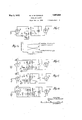
- Fig. 1 shows a sim le unneutralized radiofrequency amplifier clrcuit including an intertube coupling system arranged in accordance with this invention.
- Fig. 2 illustrates a circuit similar to Fig.
- FIG. 3 is similar to the arrangement of Fig. 1 with the addition of a parallel plate 4 feed, whereby the plate current does not pass thru'the primary winding of the coupling transformer.
- Fig. 4 is similar to Fig. lv'vith the addition of plate-circuit neutralization, i. e., a third circuit is provided for neutralizing the grid-plate coupling capacity of the tube.
- Fig. 5 is similar to the modified form of Fig. 2, but with the addition of plate-circuit neutralization.
- Fig. 6 The arrangement of Fig. 6 is derived from Figs. 4 and5 with grid-circuit neutralization substituted for the plate-circuit neutralization of those-figures.
- circuit of-Fig.'7 is a modification of Fig. 1 by which the amplification/frequency curve is made more nearly level.
- Fig. 7a illustratesapproximately the amplificationfrequency curve obtained fromthe arrangement of Fig. 7.
- Fig. 8 combines the advantages of Figs. 4 and Fig. 9 is similar to Fig. 4;, but includes an alternative means for shifting from one frequency band tov another.
- Fig. 10 is a modification of Fig. 8, and embodies a double switching arrangement.
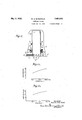
- Fig. 11 is a cross-sectional View of a coupling transformer arranged in accordance with this invention.
- Fig. 11a and Fig. 116 Show the amplification/frequency curves ofthe transformer of i Fig. 11 over two diiferent frequency bands.
- Fig. 12 shows a radio-frequency amplifier, similar to that of Fig. 4, coupled by a special system to an antenna system.
- Fig. 13 is similar to Fig. 12 except that-the antenna coupling system corresponds more closely to the intertube coupling system hereinbefore described.
- Fig. 14 illustrates the approximate frequency characteristics of the antenna system of Figs. 12 and 13 over the particular two frequency bands considered.
- The-circuit diagram of Fig.1 represents a tuned radio-frequency amplifier including two vacuum tubes A and A coupled by means of a system in accordance with this invention, including a coupling transformer ience of the present discussion, the highfrequency tuning band may be considered as that between 500 and 1500 kilocycles, and the low-frequency tuning band as that'between 1 150 and'300 kilocycles, these two bands being those at present employed for radio broad casting in England.
- This particular example is given only as a specific illustration of one embodiment of the invention.
- the invention may be used to advantage in radio receivers adapted to respond to the two' broadcasting bands at present in effect in the United States, i. e., the band between-500 and 1500 kilocycles and that between .5000 and 7500 kilocycles.
- a single-pole switch S is shunted across winding L, to act as a band-changing control.
- the switch S When used 'for the reception of the lower radio-frequency band, the switch S is opened, whereby the primary inductances L and L, are in series in the plate circuit of vacuum tube A and the secondary windings may be considered as a single primary windsystem, the cites entire primary Winding, in which event nec L and L, are in series in the input circuit of vacuum tube A
- These two sets of windings then function like a single low radiofrequency transformer.
- Variable condenser C connected to the extreme terminals of L and L then operates to tune the coupling system overthis band. mien it is desired to receive Over the high-frequency band; the switch S is closed, thus short-circuiting the low-frequency secondary L but leaving in circuit the high-frequency secondary L with the variable tuning condenser C connected across its extremities.
- switch S may be a simple single arm, single-contact switch, whose arm is always maintained at a I fixed base potential.
- this potential is that of the cathode or filament, usually known as ground pbtential, and thus the switching device introduces practically no losses into the circuits.
- the entire coupling system is so designed that the single variable condenser .0, having the proper capacity range, is equally useful for tuning, alternatively, over the low-frequency, or long-wavelength, band and the high-frequency, or short-wavelength, band, and over still other hands, if necessary.
- the single variable condenser .0 having the proper capacity range, is equally useful for tuning, alternatively, over the low-frequency, or long-wavelength, band and the high-frequency, or short-wavelength, band, and over still other hands, if necessary.
- both primary windings L and L remain connected.
- the two primary COllS L and L ing associated with the secondaries L and L When used for the reception of low frequencies, the two primary COllS L and L ing associated with the secondaries L and L (It is for this reason that Fig. 2 shows coils L L as a single winding.)
- e primary winding When functioning as a high-frequency coupling e primary winding may 1 L and the secondary e the electrical constants he primary L has relaig with the secondary L drought about by a proper be considered as as only 11,, heczn are chosen'so that tively small cor
- the high-frequency primary L may comprise a relatively small inductance closely coupled to the high-frequency secondary L
- the low-frequency primary L connected in series with the liigh frequency primary L comprises a larger inductance than 11,.
- the short-circuiting switch S is opened: thereby causing the entire secondary winding to be coupled to the cssary transfer of energy from the primary to the s *ondary is secured in most part by the relzztrjvely close coupl ng between the low-frequency primary L, and the low-frequency secondary L,.
- a slight increase in transfer of energy from primary to secondary is then efi'ected thru the combined couplings of L and L with the high-frequency secondary L5.
- short-circuiting the low-frequency secondary coil L has a pronounced effect upon the high frequency secondary L if these two coils are placed too close, togetherf
- This effect varies with the dimensions and electrical characteristics of the respective windings, but in transformers such as herein described, the too close proximity of the short-circ'uited coil L to coil L results in a pronounced increase in resistance in the coil L thereby decreasing the amplification and the selectivity within the high-frequencyband.
- Fig. 2 The arrangement of Fig. 2 is substantially the same as that of Fig. 1 with the exception that the separate primary'coils L and L are here combined into asingle winding-L L With such an arrangement the best results are obtained by employing a relatively large primary winding; that is, its inductance should be of the'same order of magni- 85 'tude as the combined inductances of the primary windings L and L of Fig. 1, and so associated with.the secondarywindings L and L5 as to produce the required mutualv inductances between coil L L and each 40 coil L and L More specifically, the mutual inductance between L 2 and L for the.
- FIG. 3 shows a modification of the arrangement of Figs. 1 and 2 in that the plate voltage for the amplifying tube A is supplied. thru a separate parallel feed including the highfrequency choke coil, (or alternatively a resistance) L...
- a stopping condenser connected between the high-potential end of choke L and the high-potential end of highfrequency primary winding L serves at ofice to by-pass the radio-frequency current in the output circuit of tube A around the direct-current 'path B, L to. the primary windings, and to insulate the platepotential from the primary "windings of the transformer.
- Fig. l'type of coupling type shown in Fig. 2 could as well be'em ployed.
- radiofrequency amplifier stage means for neutralizing the grid-plate capacitive coupling of the 2 and 6' may*' be useditoj couple; an a'ntennato" an amplifier- 1 in which case the extreme: terminalsiof Li and- L; may be con-nected' tothe antenna andz:
- neutralizing coils N and N connected in series have been added to the coupling system of Fig. 1; N bein closely coupled to hig'h-fre- 'quency primary 1 and neutralizing winding N bein closely coupled to low-frequency primary
- Fig. 5 is a further development of plate circuit neutralization as applied to the modified couplin system of Fig. 2; the explanation given a ove in connection with that figure being applicable to Fig. 5 with equal efiect. It will be noted that in this arrangement, the neutralizing coils N N have been I combined into a single winding in the. same manner that the primary coils L L have been combined.
- Fig. 6 shows the present invention in the.
- the neutralizing capacity is n jfl n F lr;
- C is the capacit existing between the grid and plate termina s.
- Fig. 7 illustrates furthermodifications of Fig. 1 by which the low-frequency primary winding'L ispurposely loaded either by means of the distributed ca acity of the winding itself, or by a physical condenser connected to the winding so that the whole may be resonant at a preselected freqpency ands.
- condenser C connects the plate battery, B, to the lower terminalof inductance L 1. .e., that the addi- .tional resonant circuit (5 L is not connected.
- the purpose of this modification is to provide a nearly level amplification/ frequency curve over the high-frequency tuning band..
- the lowrequency primary winding L has a definite coupling with high-frequency secondary coil L Since the coil L has more turns than the coil' L, the former mayhave considerable electromagnetic coupling with the secondary coil L even though it is not as close to L as is coil L
- the inductanceof L being much larger than that of L, the coil L when'considered in conjunction with its distributed capacity and any efiective supplemental capacity 0 should be resonant at a frequency between the maximum frequency of the lowfrequency band and the frequency of the. high-frequency band, such as 450 kilocycles. Accordingly, the circuit condition is. e
- Fig. 7a which shows t e ainpllfication/frequency curves with on coil L in the primary circuit; with only L and C and with both coils functioning together in the improved manner.
- the upper curve which is .known, the undesirable characteristics of amplifiers and coupling systems -are usually more pronounced at the hi her frequencies. If, however, it is desired t at the low-frequency .band shall also have a substantially level over-all amplification, the same principles may be applied. Toillustrate: the
- inductance of coil L is made much greater than that of L and the capacity C, of such value that the circuit C5, L is resonant at a frequency lower than 150 kilocycles, such as 100 kilocycles;
- the coil L is then so placed relative to coil -L that the coupling between L; and L predominates at the lower frequencies of the low-frequenc band; whereas the coupling between Lg an L predominates at thehigher frequencies of the low-frequency band.
- Altho Fig. 7a is shown to represent only the high-frequency band, it can as well be considered to represent the amplification over the low-frequency band as just described,
- Fig. 8 is fundamentally a duplication of Fig. 7, but with the addition of plate-circuit neutralization of the, grid-plate capacity of tube A
- circuit C L of Fig. 7 is omitted, and the physical condenser C of Fig. 7 is replaced bythe natural capacity resulting especially from the presence of the additional neutralizing windings N N
- the gridplate capacity of the amplifying tubes be neutralized to assure stability.
- addition of the necessary neutralizing winding has frequently introduced additional distributed capacities in the coupling transformer which in themselves have been detrimental.
- the interstage cou- 'pling transformers as provided in the modification of Fig.
- Fig. 9 shows a modification of the circuit arrangement of Fig. 4 in which, when operation is desired within the high-frequency vband the switch S is closed, connecting the coil 1:1 in parallel with L thereby reducing the inductance of the secondary system.
- This arrangement necessitates that the coil L have more inductance than inthe arrangement of Fig. 4, since that coil must provide all of the required inductance when operating within the low-frequency band.
- Coil L may, or may not, be coupled to L and hence its polarity with respect to L, may, or may not, respectively, be opposite.
- the circuit of Fig. 10 is similar to that of v Fig. 4 except that coils N and N are interchanged'in the neutralizing circuit, and further that the switch S short-circuits the neutralizing winding N and secondary winding L simultaneously.
- the efl'ect of the short-circuiting switch is thus more complete than in the precedin figures where only the low-frequency secon ary coil has been shown to be short-circuited.
- the object is, of course, to short-circuit the primary L the neutralizing winding N and the secondary S It is, however, electrically undesirable to short-cir- 'cuit coil L because neither end of it is at ground potential.
- FIG. 11 is a cross-sectional view. Reference to the figure "will disclose that the device includes an insulating tube 1 upon which are wound and sup orted the various windings already descri d.
- the tube 1 has an outside diameter of 1% inchesand a length frequenc secondary winding L, is wound'in' a single ayer over the upper portion of the insulating tube, while the comparatively fewer turns of the high-frequency neutralizing winding N are placedin a single layer immediately on top of the low-potential end of the secondarywindi-ng; the high-frequency primary winding L being wound in asingle layer immediately over the neutralizing winding, the layers being separated by insulation such as celluloid of about .01 inch thickness.
- Thesethree windings thus comprise a com plete high-frequency transformer.
- the lowfrequency transformer is wound upon and supported by the same insulating tube 1 on the lower portion thereof.
- the neutralizing winding N is wound in a single la er on the insulating tube, the primary windin L being wound on and immediately over the neutralizing winding, the low-frequency secondary winding L, of the multi-layer type beingplaced over the primary winding L an insulating layer being laced between the windings, as before.
- T e spacinv between the high-frequency transformer and the lowfrequency transformer, along the axis of the insulating tube 1, should be such that the two transformers have a negligible magnetic influence upon each other.
- the exact spacing required depends largely upon the frequency bands for which the .diiferent transformers are designed, and also upon the de-' 'gree of amplification per stage and upon the over-all amplification of the complete ampli-- fier. In eneral, this spacing must be about En-the structure illustrated, the lowfrequency primary and neutralizin coils L N are spaced 4 inch from the highequency secondary L and the low-frequency secondary L is spaced 1 3' inch from the quency secondary L Under'some circumstances, such as when it is inconvenient to provide the required spacing due to other spaceYlimita-tions in the apparatus, or when the chosenfrequency bands require 1t.it is necessary to electromagneticalillustrated in Fig.
- thisfcan may be so shaped that'it is' spaced about the same dis.- tance from the windings of'both. transform- 1y shield or screen the separate transformers. one from the other by means of a metallic shield, individualto each transformer, and
- the transformer structure may be secured to the can with suitably positioned machine screws or rivets 6, and' high-fre- 1 similar screws and spacers maylikewisebe provided at the upper end of' the transform er, altho these are not shown in the drawings.
- spacers To connectthe various windings of the trans former permanently in their respective cir-' spaced therefrom by spacers 3. If required,
- terminal lugs 2 may be provided around required, additional windings (see Fig. 7)
- merican gauge 12 turns; L 12turns; N 30 turns; L 30 turns; L 321 turns of double silk-covered high-frequency cable-of 20' strands of No.38 (American gauge) enamelled copper wire.
- Tuning condenser, C (or C) Minimum capacity" 15 f. (approximately) Maximum capacity 400 f. (approximately) Neutralizing condenser capacity I Gu 4.5 f. (approximately)
- Fig. 11a and Fig. 111) show the approximate amplification characteristics of the high-frequency transformer and the lowfrequency transformer, respectively, of the structure illustrated in Fig. 11.
- Fig. 10 shows how this may be accomplishedby the use of an additional single-contact switch arranged to short-circuit the low-frequency neutralizing winding N simultaneously with the shortcircuiting of low-frequency secondary L Both operations may readily be accomplished with any well constructed double-arm switch.
- This antenna coupling system is designed, with comparatively loose I coupling between primary L and secondary L so that a change in antenna capacity shall have but negligible effect upon the first tuned input circuit, thus making uni-control of the several tuning condensers possible, and additionally with the provision of" an antenna coupling system amplification curve whose slope is substantially the reverse of that of the inter-tube coupling system curve.
- the antenna inductance L should be of such value that-with the-usual antenna capacity the reactance will always be inductive over the high-frequency band.
- the coil L. might have an inductance of 500 microhenries, and with the usual antenna capacity be resonant at about 400 kilocycles.
- the secondary coil L may, in general, have characteristics similar to those of secondary coil L L of the inter-stage coupling system.
- the switch S is similar in its function to switch S already described in connection with Fig. 1, both switches being intended to be operated.simultaneously.
- the circuit arrangement of Fig. 13 is similar to that of Fig. 12 insofar as the inter-tube coupling system is concerned, but differs therefrom in its antenna coupling system.
- the antenna coupling system is more nearly symmetrical with that of the intertube coupling system.
- the present antenna circuit is designed so as to have a capacitive reactance thruout the entire operating frequency range including both bands.
- the secondary inductances L and L are normally identical with secondary inductances L and L
- the primary inductances L and L may be identical with primary inductances L and L but this depends upon the antenna employed. The arrangement, thus, does not result in the characteristics of the antenna coupling system of Fig.
- the curves of Fig. 14 illustrate specifically the approximate amplification/frequency characteristics of the antenna coupling system of Fig. 12. Since the antenna circuit is resonant at a frequency between300 and 500 kilocycles, the highest points on the two amplification curves correspond to these two operating frequenciesnearest the resonant frequency of the antenna circuit. The two amplification curves are lowest at 150 and 1500 1 'kilocycles, the two operating frequencies farthest removed from the resonant frequency of the antenna circuit, but the amplification is still sufliciently great at. allfrequencies within the two operating hands. This last result is best accomplished by the antenna circuit of Fig. 12. 1 s
- I I In a radio receiver adapted to operate over a high-frequency band and over a low frequency band, a plurality of substantially identical tunable circuits including inductance coupled together in succession,-a single band-changing control interconnecting a plurality of switches each having a single contact and an arm maintained always at a fixed base potential, one switch only being connected in each circuitand adapted to modify said inductance, and uni-control'means for simultaneously tuning said circuits.
- a tuned multistage radio-frequency amplifier adapted to operate over a high-frequency band and over a lowfrequency band, each stage including inductance, a single band-changing control interconnecting a plurality of switches each having a single contact and an arm maintained always at a fixed base potential, one switch only being connected in each stage and adapted to modify said inductance, and unicontrol means for simultaneously tuning said stages.
- a radio receiver including a multistage tuned radio-frequency vacuum tube amplifier adapted to operate over a high-frequency band and over a low-frequency band, each stage including a plurality of sets of inductances said bands being separated by an intermediate'frequency band, a single bandchanging control interconnecting a plurality of single-contact switches, one switch only being connected in each stage and adapted to modify one-of said sets of inductances, and uni-control means for simultaneously tuning said stages.
- a radio-frequency coupling system adapted to operate over' a plurality of widely different frequency bands, said system including a plurality of secondary windings coupled to at least one primary winding, and a singlecontact'switch connected to one of said secondary windings whereby the closure of said switch effects a substantial change in the inductance both of the secondary winding to which said switch is connected and of the primary winding coupled thereto, said switch baing the only short-circuiting switch in said s age- 1 v 5.
- A- radio-frequency coupling system adapted to operate overa plurality of widely different frequency bands, said system including a plurality of secondary windings coupled to at least one primary winding, and
- a single-contact switch connected across one of said secondary windings but all of said primary windings remaining in circuit whereby the closure of said switch effects a substantial decrease in the inductance both of the secondary winding across which said switch is conprimary winding coupled transformer having two series-connected secondary windings coupled toat least one primary winding, and a single-contact switch the closure of which materially changes the inductance of one of said secondary windings and of the primary winding coupled tubes in a radio-frequency amplifier adapted to operate over a high-frequency band and over a low-frequency band, said bands being separated by an intermediate-frequency band, said system including at least one primary winding connected in the output circuit of the first of said tubes, a high-frequency secondary winding and a low-frequency secondary winding connected in series in the input circuit of a second of said tubes, a variable condenser connected across said pair of secondary windings, the low-frequency secondary winding being coupled to at least one primary winding, and a switch connected across only said low-frequency secondary winding to short
- Atuned radio-frequency coupling system connected between successive vacuum tubes in a radio-frequency amplifier adapted to-operate over a high-frequency band and over a low-frequency band, said bands being separated by an intermediate-frequency band, said system including a. low-frequency and a high-frequency primary winding connected in series in the output circuit of a first of said tubes, a low-frequency and a high-frequency secondary winding connected in series in the input circuit of a second of said tubes, both of said low-frequency windings being coupled together and both of said high-frequency windings being coupled together, and a switch connected across only said low-frequency secondary winding to short-circuit the cinductance thereof and thereby to materially reduce the inductance of the low-frequency primary winding coupled to said low-frequency secondary winding.
- a tuned radio-frequency coupling system connected between successive vacuum tubes in a radio-frequency amplifier adapted to operate over a high-frequency band and over a low-frequency band, each of said tubes having input and output circuits, including a cathode, said bands being separated by an intermediate-frequency band, said system comprising a transformer having tunable high-frequency and low-frequency secondary windings connected'in series in the input circuit of the second of said vacuum tubes, said transformer having a certain primary winding connected in the output circuit of the first of said vacuum tubes and coupled to said low-- frequency secondary winding, said first vacu um tube having undesirable capacitive coupling between its input and output circuits,
- a single-pole switch operable to short-circuit the inductance of said low-frequency secondary winding and thereby to effectively rebericht the inductance of said neutralizing winding and of said primary winding coupled thereto.
- a radio frequency coupling system adapted to operate over a high-frequency band and over a low-frequency band, said system including a set of high-frequency windings and a set of low-frequency windings, and a single-pole switch for effectively connecting one of said sets of windings in and out of operation, the arm of said switch being always maintained at a fixed base potential.
- a radiofrequency coupling system adapted to operate over a high-frequency band and over a low-frequency band, said system including a set of high-frequency windings and a set of low-frequency windings, and a switch 'connected across only one of said low-frequency windings for materially reducing the eflective inductance of all of said low-frequency windings.
- a radio frequency coupling system adapted to operate over a high-frequency band and over a low-frequency band, said system including a low-frequency primary winding connected in series with a high-fre quency primary winding, and a low-frequency secondary winding connected in series with a high-frequency secondary winding, said high-frequency windings and said. low-fie quency windings being respectively coupled.
- said system including a low-frequency primary winding connected in series with a high-frequency primary winding, and a low-frequency secondary winding connected in series with a high-frequency secondary winding, said low-frequency windings and said high-frequency windings being respectively coupled together, and a single-contact switch connected to short-circuit said low-frequency secondary winding and thereby to reduce the effective inductance of said low-frequency primary winding while said system is operating within said high-frequency band.
- a radio-frequency coupling system adapted to operate over a high-frequency band and over a low-freq ency band, said system including a lowrequency primary winding connected 1n serles with "a high-frequency primary winding, and a low-frequenhigh-frequency and a low-frequency' winding connected in series in the output circuit of one of said vacuum tubes, a high-frequency and a low-frequency secondary winding connected in series in the input circuit of the nextv succeeding vacuum tube, the high-frequency windings and low-frequency windings being respectively coupled together, and a singlepole single-contact switch operable to shortcircuit the low-frequency secondary; winding while said amplifier is operated within said high-frequency band.
- a tuned radio-frequency coupling system connected between successive vacuum tubes in a radio-frequency amplifier adapted to operate over a high-frequency band and over a low-frequency band, saidbandsbeing separated by an intermediate-frequency band, said system including a high-frequency and a low-frequency primary winding connected inseries in the output circuit of one I of said vacuum tubes, a tunable high-fie.
- a single-poleswitch operable to shortcircuit the low-frequency secondary winding quency and a low-frequency primary wind ing connected in series in the output circuit of said first vacuum tube, a high-frequency and low-frequency secondary winding, said secondary winding being tunable, connected in series in the input circuit of the next succeeding tube, a high-frequency and a lowfrequency neutralizing winding connected in series with a neutralizing capacity between the grid of said first tube and its filament system, all of said high-frequency windings being magnetically coupled together and all of said low-frequency windings being magnetically coupled together, and a single-pole switch operable to materially reduce the effective inductance of all of said low-frequency windings While said system is tuned within the high-frequency band.
- a radio-frequency coupling system connected between successive vacuum tubes in a radio-frequency amplifier adapted to opcrate over a high-frequency band and over a low-frequency band, said bands being separated by anintermediate-frequency band, said system including a set of high-frequency windings and a set of low-frequency windings, and a single-pole switch for effectivelyshort-circuiting said set of low-frequency windings while said system is operated within said high-frequency band.
- a multistage radio-frequency coupling system adapted to operate over a high-frequency band and over a low-frequency band, said bands being separated by an intermediate-frequency band, each stage including a transformer having two series-connected secondary windings coupled to at least one primary winding, and a single-contact switch, the simultaneous closure of the switches in said stages being operative in each stage to materially change simultaneously the inductance of one of the secondary windings and of the primary winding coupled thereto.
- a radio-frequency coupling system adapted to operate over a highhand, said system including a' set of highfrequency windings and a set of low-frequency windings, means comprising in each stage a single-pole single-contact switch, said switch being the only switch in each stage,
- a multistage radio-frequency amplifier adapted to operate over a high-frequency hand and over a low-frequency band, said bands being separated by an intermediatefrequency band, each stage including a vacuum tube and a tuned radio-frequency coupling system, said system including at least oneprimary winding connected in the output circuit ofthe vacuum tube in the first of said stages, a pair of high-frequency and low-frequency secondary windings connected in series in the input circuit of'the vacuum so tube inthe second of said stages, a variable condenser connected across said pair of secondary windings, the low-frequency secondary winding being coupled to at least one primary winding, a switch connected across 5 only said low-frequency secondary windin to short-circuit the inductance thereof an thereby to materially reduce the effective inductance of the primary winding coupled to said low-frequency secondary winding, and means interconnecting the several switches whereby they may be operated simultaneousl l 23
- a tuned radio-frequency coupling system connected between successive vacuum tubes in a radio-frequency amplifier each of said tubes having an anode, cath
- a radio-frequency vacuum tube amplifier each of said tubes having an anode
- said amplifier being adapted to operate over a high-frequency band and over a low-frequency band, said bands being separated by an intermediatefrequency band
- said amplifier including a tuned radio-frequency coupling system connected between adjacent tubes, said system comprising a transformer having high-frequency and low-frequency secondary windings connected in series in the input circuit of the second of said vacuum tubes, a variable condenser connected across the secondary wlndingsof said second vacuum tube, said transformer having a certain primary winda tube having undesirable capacitive coupling ing connected in the output circuit of the first of said vacuum tubes and coupled to said low-frequency secondary Winding, highfrequency and low-frequency secondary windings shunted by a variable condenser and connected in series in the input circuit of said first vacuum tube, a primary winding coupled to said last-mentioned low-frequency secondary winding, said first vacuum between its input and output circuits, means for neutralizing said capacitive coupling including at least one neutralizing winding coupled to said certain primary winding and to said first-menti
- said system including a high-frequency primary winding connected in series with a low-frequency primary winding, and a high-frequency secondary winding connected inseries with a low-frequency secondary' winding, said high-frequency wind ingsand said low-frequency windings being respectively coupledv together, said low-frequency primary winding being efl'ectively shunted by a capacity whereby it is resonant at a frequency within said intermediate-frequency band, and a single-contact switch conneoted to short-circuit said low-frequency secondary winding and thereby to reduce the vefiective inductance of said low-freqlilency in series with a low-frequency primary windmg, and a high-frequency secondary winding connected in series with a low-frequency secondary winding, said high-frequency windings and said low-frequency windings being respectively coupled together, means for variably tuning said secondary windings over said high-frequency band and over said low-frequency band, said low-frequency primary Winding
- a radio receiving system an antenna circuit, a tuned radio-frequency amplifier including-a plurality of' vacuum tubes cou pled by a tuned radio-frequency coupling system, said coupling system being adapted to operate over a high-frequency band and over a low-frequency band, said bands being separated by an intermediate-frequency band, said system including a high-frequency primary winding and a low-frequency primary winding connected in series in the output circuit of the first of said tubes, a highfrequency secondary winding and a low-frequency secondary winding connected in series in the input circuit of a second of said tubes, said high frequency windings being magnetically coupled together and said low-frequency windings being magnetically coupled together, a variable tuning condenser connected across said secondary windings, and a single-contact switch connected across said lowfrequency secondary winding to short circuit the same, the first of said vacuum tubes being coupled to said antenna circuit by a tuned coupling system including a primary winding connected in said antenna circuit and loosely coupled to a high-frequency secondary winding, said last-
- a tuned radio-frequency coupling system connected betwen successive vacuum tubes in a radio-frequency amplifier, said tubes having input and output circuits including a grid, cathode and anode, said amplifier being adapted to operate over a highfrequency band and over a low-frequency band, a first vacuum tube of said amplifier having undesirable capacitive coupling between its input and output circuits, said system comprising a pair of high-frequency and low-frequency primary windings connested in series in the output circuit of said first vacuum tube, a pair of tunable highfrequency and low-frequency secondary windings connected in series in the input circuit of the next succeeding vacuum tube, a pair of high-frequency and low-frequency neutralizing windings connected in series with a neutralizing capacity between the grid of said first tube and the cathode system, all
- said high-frequency windings being magnetically coupled together and all of said low-frequency windings being magnetically coupled together, and a switch having a contact connected to one end of said low-frequency secondary winding and an arm connected to the cathode system for effectively short-circuiting at least a portion of the inductance of all of said low-frequency windings while said system is tuned within the high-frequency band.
- a tuned radio frequency coupling system adapted to operate over a pluralityof frequency bands, said system including at leastone primary winding and a plurality of secondary windings, means for tuning said secondary windings, capacity shunting said primary winding and of such Value that the combination of saidcapacity and said prima winding is capacitively reactive to the highest of said frequency bands, and means to short circuit at leastone of the secondary windings whereby the frequency range over which said tuning means tunes said secondary windings is changed from a lower to a higher of said frequency bands.
- a radio coupling system according to claim 29 wherein said short circuiting means comprises a switch having a single arm and a single contact, said arm being maintained at ground potential and being arranged to effectively short circuit at least one of said second ary windings.
- a radio frequency amplifier a plurality of amplifying vacuum tubes, said tubes beingcoupled by a coupling system in accordance with claim 29, and uni-control means for simultaneously operating the short circuiting means of all the coupling systems.
- a tuned radio frequency coupling system adapted to operate over two frequency bands, saidsystem including a primary wind ing and a plurality of secondary windings coupledthereto, a capacity shunting said primary winding and of such value that the cir- -cuit consisting of said capacity and said pricluded another primary winding in series with said first primary winding, said other primary winding being resonant at a frequency lower than the lower of said frequency bands, whereby substantially uniform ampli- ⁇ icatiion is obtained over both said frequency an s.
- said system including input and output circuits, said input circuit including at least one inductance and said output circuit including a plurality of inductances, means for tuning said output circuit, capacity shunting said input inductance and ofsuch value that the combination of said capacity and said inductance is capacitively reactiveto the 36.
- said short-circuiting means comprises a switch having a single arm and a single contact, said arm being maintained at ground potential and being arranged to efiectively short circuit at least one of said windings of the output circuit.
- a tuned radio frequency coupling system adapted to operate over a plurality of frequency bands, said system including at least one primary winding and a plurality of secondary windings, means for tuning said secondary windings, capacity shunting said primary winding and 0 such value that the combination of said capacity and said primary winding is capacitively reactive to the highest of said frequency bands, and means to short circuit at least one of the secondary windings,,whereby the frequency range over which said tuning means tunes said secondary windings is changed from a lowerto a higher of said frequency bands.
- a radio frequency coupling system accordingto claim 39 wherein there exists at least dual coupling between said primary and secondary windings.
- said short-circuiting means comprises a switch having a single .arm, saidarm being maintained at ground potential and being arranged to selectively short circuit said secondary windings.
Landscapes
- Engineering & Computer Science (AREA)
- Power Engineering (AREA)
- Amplifiers (AREA)
Description
May 3,1932. AMMDONALD 1,851,055
COUPLING SYSTEM 7 Filed Feb. 15, 1929 4 Shets-$heet 1 ATTORNEY5 May 3, 1932. w. A. M DONALD 1,357,055
I COUPLING SYSTEM Filed Feb. 15, 1929 4 Sheets-Sheet 2 INVENTOR PM biz W Mama.
ATTORNEYS May 3, 1932.
w. A. M DONALD ,0 5
COUPLING SYSTEM Filed Feb. 15, 1929 .4 Sheets-Sheet 3 I 500 loco 7 I500 KC.
FREQUENCY INVENTOR ATTORNEY-5 May 3, 1932- w. A. M E JONALD 1,857,055
COUPLING SYSTEM Fi led Feb. 15, 1929 4 Sheets-Sheet 4 HIGH-FREQUENCY ext/v0 500 lo oo 5 00 KC.
I50 300 Kc.
FREQUENCY INVENTOR A'ITORNEYS Patented May 3, 1932 UNITED STATES PATENT =o-I-"1=lct:'. i
-. WILLIAM A. mcnoNALn, or LITTLE nncmnnw Yonx; ASSIGNOB' 'ro nzAzmjrmn con.-
POBATION, OF JERSEY CITY, nEw JERSEY, A conron rIon or DELAWARE Application filed February 15, 1929,
This invention relates to radio coupling, systems particularly to transformers for use in coupling two successive vacuum tubes in a radio-frequency amplifier, and also in coupling an antenna system to such an amplifier, intended for the efficient reception of two or more diiferent frequency, or wavelength, bands.. q
To this end the invention employs coupling transformers having a multiplicity of windings so related to each other that the several primary coils operate as asingle primary and the several secondary coils operate-as a single secondary over one given frequency band, but that only certain of the primary and secondary coils operate as a single transformer over a nother given frequency band. A further feature of the invention is an improved. frequency-amplification characteristic by reason of the provision of precalculated reactions between the various coils.
In the past, three expedients have been most commonly employed for the reception of two or more widely differing frequency, or wavelength, bands. The first, and most obvious, is the use of as many separate receivers or amplifiers as there are different bands to be received. The second consists in employing a separatetransformer especially designed for'each separate frequency band; the various transformers being provided with plug term nals which, when inserted in a suitable holder or .receptacle, automatically establish the required electrical connections with the associated apparatus. The third expedient consists in permanently mounting as many physically separate transformers as there are diiferent frequency bands to be received, and shift ng the connections of the transformers with the associated apparatus from one transformer to another by means of an appropriate multi-point switching de- VlCe.
The main objection to the first expedient is obviously that it is economically impracticable because of the attendant duplication of apparatus. The second and third expedients have, therefore, been proposed to main objection to the first.
The second-named arrangement is elecobviate the cournm sYsrEm Serial No. 340,244, and in Greatjritain and Australia February 15,1829;
trically sound, but is clumsy and undesirable from the point of view of operation, because -a shift from one frequenc band to another necessitatesthe opening the receiver cabinet, the removal of one coil and the insertion 'of another. This operation is especially undesirable when the arrangement is employed in .a multi-stage amplifier because In such event it is necessary to change a number of transformers, which operation entails a considerable delay in tuning. Furthermore, in this second arrangement, it frequently happens that the spare transformers, i. e., those not for the moment employed within the receiver, become damaged or lost. Finally, the
construction and duplication of such plugin transformers is necessarily expensive.
In the case of the third-mentioned expedient. the use of two or more entire sets of transformers within the receiver is objectionable because of the additional space required and because of the increased cost.
urthermore, all the switching devices fo'r'this apparatus thus far proposed are complicated, expensive, and subject to failure both electrically and mechanically. In the case of multi-stage amplifiers wherein large degrees ficiency wherebv high amplification may be attained; but utilizes a more simple electrical and mechanical structure than has heretofore been employed in the reception of a plurality of frequency bands. Anadditional advantage of theinvention results from the design of the transformers such that uniform, or substantially uniform, amplification is attained over one or more of the frequency bands, as.
desired. This invention overcomes all of the 30 another.
disadvantage of the (prior arrangements, as
pointed out, by provi ing a single transformer structure WhlCh may be permanently fitted. inthe receiver or amplifier, but which includes at least as many sets of windings as there are frequency bands to be, received; the change from one frequenc band to another being accomplished by siort-circuiting or open-circuiting'one or more of the unused coils in each transformer, such as the secondary coil for example, in which case the primary coils are always connected in circuit.
Before describing the invention with the aid of the accompanying drawings, it should be pointed out that this invention is not limited to use in tuned amplifier circuits but may be used witlrgood success in untuned amplifiers. The invention-is adapted to be used not only in combination with the common three-element tube, but also with the four-element tube, commonly known as the shield, or screen-grid, tube (the particular type of tube employed having no special re- 26 lation to this invention) it may likewise be employed as a coupling device in amplifiers whether or not they include neutralization, and for coupling the amplifierto an antenna as well as for coupling one vacuum tube with By neutralization is meant the neutralization of the capacitive coupling between two elements or electrodes of a vacuum tube together with the associated wiring,
- whereby the tendency towards the production of oscillations is reduced or eliminated.
Referring to the drawings:
Fig. 1 shows a sim le unneutralized radiofrequency amplifier clrcuit including an intertube coupling system arranged in accordance with this invention.
Fig. 2 illustrates a circuit similar to Fig.
' 1, but slightly modified.
'Fig. 3 is similar to the arrangement of Fig. 1 with the addition of a parallel plate 4 feed, whereby the plate current does not pass thru'the primary winding of the coupling transformer. I
Fig. 4 is similar to Fig. lv'vith the addition of plate-circuit neutralization, i. e., a third circuit is provided for neutralizing the grid-plate coupling capacity of the tube.
Fig. 5 is similar to the modified form of Fig. 2, but with the addition of plate-circuit neutralization.
The arrangement of Fig. 6 is derived from Figs. 4 and5 with grid-circuit neutralization substituted for the plate-circuit neutralization of those-figures.
6o The circuit of-Fig.'7 is a modification of Fig. 1 by which the amplification/frequency curve is made more nearly level. i
Fig. 7a illustratesapproximately the amplificationfrequency curve obtained fromthe arrangement of Fig. 7.
Fig. 8 combines the advantages of Figs. 4 and Fig. 9 is similar to Fig. 4;, but includes an alternative means for shifting from one frequency band tov another.
Fig. 10 is a modification of Fig. 8, and embodies a double switching arrangement. Fig. 11 is a cross-sectional View of a coupling transformer arranged in accordance with this invention.
Fig. 11a and Fig. 116 Show the amplification/frequency curves ofthe transformer of i Fig. 11 over two diiferent frequency bands.
Fig. 12 shows a radio-frequency amplifier, similar to that of Fig. 4, coupled by a special system to an antenna system. I
Fig. 13 is similar to Fig. 12 except that-the antenna coupling system corresponds more closely to the intertube coupling system hereinbefore described.
Fig. 14 illustrates the approximate frequency characteristics of the antenna system of Figs. 12 and 13 over the particular two frequency bands considered.
The-circuit diagram of Fig.1 represents a tuned radio-frequency amplifier including two vacuum tubes A and A coupled by means of a system in accordance with this invention, including a coupling transformer ience of the present discussion, the highfrequency tuning band may be considered as that between 500 and 1500 kilocycles, and the low-frequency tuning band as that'between 1 150 and'300 kilocycles, these two bands being those at present employed for radio broad casting in England. This particular example, however, is given only as a specific illustration of one embodiment of the invention;
for obviously, other frequencyv bands may as wellbe accommodated. For instance, the invention may be used to advantage in radio receivers adapted to respond to the two' broadcasting bands at present in effect in the United States, i. e., the band between-500 and 1500 kilocycles and that between .5000 and 7500 kilocycles.
A single-pole switch S is shunted across winding L, to act as a band-changing control. When used 'for the reception of the lower radio-frequency band, the switch S is opened, whereby the primary inductances L and L, are in series in the plate circuit of vacuum tube A and the secondary windings may be considered as a single primary windsystem, the cites entire primary Winding, in which event nec L and L, are in series in the input circuit of vacuum tube A These two sets of windings then function like a single low radiofrequency transformer. Variable condenser C, connected to the extreme terminals of L and L then operates to tune the coupling system overthis band. mien it is desired to receive Over the high-frequency band; the switch S is closed, thus short-circuiting the low-frequency secondary L but leaving in circuit the high-frequency secondary L with the variable tuning condenser C connected across its extremities.
As is represented in the diagram, switch S may be a simple single arm, single-contact switch, whose arm is always maintained at a I fixed base potential. In all of the examples shown herein, this potential is that of the cathode or filament, usually known as ground pbtential, and thus the switching device introduces practically no losses into the circuits.
The entire coupling system is so designed that the single variable condenser .0, having the proper capacity range, is equally useful for tuning, alternatively, over the low-frequency, or long-wavelength, band and the high-frequency, or short-wavelength, band, and over still other hands, if necessary. Referance to the figure will disclose that in shifting from thelow-frequency band to the highfrequency hand, both primary windings L and L remain connected.
When used for the reception of low frequencies, the two primary COllS L and L ing associated with the secondaries L and L (It is for this reason that Fig. 2 shows coils L L as a single winding.) When functioning as a high-frequency coupling e primary winding may 1 L and the secondary e the electrical constants he primary L has relaig with the secondary L drought about by a proper be considered as as only 11,, heczn are chosen'so that tively small cor This condition selection of "'ie constants of the various coils, both individually and with respect to each other, in the following manner: The high-frequency primary L may comprise a relatively small inductance closely coupled to the high-frequency secondary L The low-frequency primary L connected in series with the liigh frequency primary L comprises a larger inductance than 11,. and
is but loosiiy coupled to the high-frequency secondary i lVhen it'is desired to receive signals within the low-frequency band, the short-circuiting switch S is opened: thereby causing the entire secondary winding to be coupled to the cssary transfer of energy from the primary to the s *ondary is secured in most part by the relzztrjvely close coupl ng between the low-frequency primary L, and the low-frequency secondary L,. A slight increase in transfer of energy from primary to secondary is then efi'ected thru the combined couplings of L and L with the high-frequency secondary L5. Obviously the major portion of the coupling for this band is between L and L The physical position of winding L with respect to L is so adjusted that the electrical efi'ect produced by the lowsfrequency primary L uponthe high-frequency secondary L is relatively small when the low-frequency secondary L is short-circuited.
Much attention must be paid to the proper choice of the electrical constants of the vari-- ous coils and to the physical, and consequenthem, are resonant at frequencies higher than the highest frequency of the respective tuning bands of the amplifier. If the resonant frequency of the primary circuit comes within a tuning-frequency band, the result may be a material reduction in the amplification and a corresponding decrease in selectivity over a large part of that band. The physical placement of certain of'the coils produces other electrical effects which must also be considered in calculating the final performance of the complete transformer. For example, short-circuiting the low-frequency secondary coil L, has a pronounced effect upon the high frequency secondary L if these two coils are placed too close, togetherf This effect varies with the dimensions and electrical characteristics of the respective windings, but in transformers such as herein described, the too close proximity of the short-circ'uited coil L to coil L results in a pronounced increase in resistance in the coil L thereby decreasing the amplification and the selectivity within the high-frequencyband.
In the circuit diagram of Fig. 1, as well as in those of the other figures, the input circuit of the first amplifying tube A is repre- 60 transformer is here represented, the mo wn' in Figs.
tube, as illustrated. I v I In no I 1 case in the drawings 'herewith'fare the filament-heating circuits of the vacuum tubes shown completed .for'thereasonthat' :itflis-now well known'in the art thatthe'fila ment. or cathode of a Vacuum tube may'be.
heated by anyof several-methods. Likewise, the plate, or output, circuit of the second -vacuum tube A in each figure'is 'showniuncompleted; but it is to be understood that such plate circuit-may be completed in the same manner as the plate circuit of the tube A 'and so on, for 'as many amplification stages as may be desired, the laststage being coupled to a detector or some other appropriate device. V
The arrangement of Fig. 2 is substantially the same as that of Fig. 1 with the exception that the separate primary'coils L and L are here combined into asingle winding-L L With such an arrangement the best results are obtained by employing a relatively large primary winding; that is, its inductance should be of the'same order of magni- 85 'tude as the combined inductances of the primary windings L and L of Fig. 1, and so associated with.the secondarywindings L and L5 as to produce the required mutualv inductances between coil L L and each 40 coil L and L More specifically, the mutual inductance between L 2 and L for the.
frequency bands assumed, should be considerably greater than the mutual inductance between L and L Fig. 3 shows a modification of the arrangement of Figs. 1 and 2 in that the plate voltage for the amplifying tube A is supplied. thru a separate parallel feed including the highfrequency choke coil, (or alternatively a resistance) L... A stopping condenser connected between the high-potential end of choke L and the high-potential end of highfrequency primary winding L serves at ofice to by-pass the radio-frequency current in the output circuit of tube A around the direct-current 'path B, L to. the primary windings, and to insulate the platepotential from the primary "windings of the transformer. 'Altho the Fig. l'type of coupling type shown in Fig. 2 could as well be'em ployed. p
It is frequently desirable to add to a radiofrequency amplifier stage means for neutralizing the grid-plate capacitive coupling of the 2 and 6'may*' be useditoj couple; an a'ntennato" an amplifier- 1 in which case the extreme: terminalsiof Li and- L; may be con-nected' tothe antenna andz:
I ground,. respectively, instead of to the plate "electrode and filament circuit of a vacuumw vacuum tube"; whereby freedom 1 from undesired?tregerferationsz-gand oscillations 1 is ata: tainedu'; In Fig; e4,'= therefore,"isshown" a c01 1; it plingiarrangement jsimil'ar toithat of Fig. 1 1,3 but with thew additionx'o'f a 'il'eutralizing .circui-t 65, N N connected rinxseries between the. griclaelectrodeand theEfilament; or cathode, L.
systelm. P Since in this'lspecific neutralization s tem the: neutralizingcoils ;l I'.' *and-'II are e ect-romagnetically coupled to plate coils L 1 and L the neutralizing condensed, O being connected toithe 'gridof the vacuum tube, the
neutralization is effected in the platecircuit. P
"The principle of late-circuit neutralization 5 is explained inv azeltine U. S. Patent No.
l,533,858,especially'as illustrated in Fig. 2
thereof, which system has been slightly modi-n fied for application to thecouplingsystem of the presentinvention. Accordingly, neutralizing coils N and N connected in series have been added to the coupling system of Fig. 1; N bein closely coupled to hig'h-fre- 'quency primary 1 and neutralizing winding N bein closely coupled to low-frequency primary By properly proportioning the six difierent windings represented in the diagram, and by properly positioning them with respect to each other, it is thus possible to obtain entirely satisfactory neutralization .over both frequency bands.
Fig. 5 is a further development of plate circuit neutralization as applied to the modified couplin system of Fig. 2; the explanation given a ove in connection with that figure being applicable to Fig. 5 with equal efiect. It will be noted that in this arrangement, the neutralizing coils N N have been I combined into a single winding in the. same manner that the primary coils L L have been combined.
Fig. 6 shows the present invention in the.
form illustrated in Fig. 2 as em loyed with an alternate form of neutralization, known as grld-clrcuit neutralization. This form is also described in the mentioned Hazeltine patent, especially in connection with Fig. 3
thereof. It will be observed that in this form .tion could be applied as easily to any or all tubes of a multistage amplifier. Because of the fact that in grid-circuit neutralization the neutralizing coil is electromagnetically cou in the'low-frequency band. Let L e ual the total effective secondary inductance o L, and L and let M equal the total effective mutual inductance between both secondary windin L and L and both neutralizing windings .L 1 and N Correspondin ly, for high-frequem cy reception, the lowrequency portion of the secondary, L is short-circui ted'by switch S which results in a slightly less effective secondary inductance than that of L alone, and a slightly higher efi'ective mutual induc- V tance with the neutralizing windings N and N than with N alone. Now, with the switch closed and L short-circuited, let L" equal: the total effective inductance of the secondary windings L L4; and let M" equal the total effective mutual inductance between both secondary windings and both neutralizin windings. To achieve satisfactory neutra ization within both the low and high-frequency bands, with no change in the value of the neutralizing condenser, thephysical position of i the secondary and neutralizing windings.
between the two tuning-frequency should be 'such that the following relation obtains: y
in which case the neutralizing capacity is n jfl n F lr;
where C, is the capacit existing between the grid and plate termina s.
Fig. 7 illustrates furthermodifications of Fig. 1 by which the low-frequency primary winding'L ispurposely loaded either by means of the distributed ca acity of the winding itself, or by a physical condenser connected to the winding so that the whole may be resonant at a preselected freqpency ands. (For the present discussion we may assume that the dotted connection above condenser C connects the plate battery, B, to the lower terminalof inductance L 1. .e., that the addi- .tional resonant circuit (5 L is not connected.) The purpose of this modification is to provide a nearly level amplification/ frequency curve over the high-frequency tuning band.. This result is accomplished by arranging the separate coils of theen ire transformer structure so that. the lowrequency primary winding L has a definite coupling with high-frequency secondary coil L Since the coil L has more turns than the coil' L, the former mayhave considerable electromagnetic coupling with the secondary coil L even though it is not as close to L as is coil L The inductanceof L being much larger than that of L, the coil L when'considered in conjunction with its distributed capacity and any efiective supplemental capacity 0 should be resonant at a frequency between the maximum frequency of the lowfrequency band and the frequency of the. high-frequency band, such as 450 kilocycles. Accordingly, the circuit condition is. e
tween L and L predominates at the lower frequencies of the high-frequency band. It
is to be understood, of course, that the secondary coil L is presumed to be short circuited 'when the above-defined conditions obtain.
The graphical representation of the manner in which these relations vary is given in Fig. 7a whichshows t e ainpllfication/frequency curves with on coil L in the primary circuit; with only L and C and with both coils functioning together in the improved manner. The upper curve, which is .known, the undesirable characteristics of amplifiers and coupling systems -are usually more pronounced at the hi her frequencies. If, however, it is desired t at the low-frequency .band shall also have a substantially level over-all amplification, the same principles may be applied. Toillustrate: the
primary coil L and its associated condenser C: have been added to the'figure, and for the present discussion may be considered to be together connected in the plate circuit of the amplifying tube A1, which isthe primary circuit of the coupling system. To accomplis h this connection the dotted line above condenser C in the figure may be considered removed. For operation over the low-frequency band the switch S is opened. The
inductance of coil L is made much greater than that of L and the capacity C, of such value that the circuit C5, L is resonant at a frequency lower than 150 kilocycles, such as 100 kilocycles; The coil L is then so placed relative to coil -L that the coupling between L; and L predominates at the lower frequencies of the low-frequenc band; whereas the coupling between Lg an L predominates at thehigher frequencies of the low-frequency band. Altho Fig. 7a is shown to represent only the high-frequency band, it can as well be considered to represent the amplification over the low-frequency band as just described,
since the typical amplication/frequencychar-' acteristics of the two bands will be practically identical if designed in accordance with the foregoing description. It is to be understood that if more than two frequency bands are included, additional circuits corresponding to C,,, L, may be connected in order that the additional frequency bands may likewise present uniform amplification characteristics.
Coupling arrangements such as those shown in Figs. 1, 2, 3 and 7 are especially,
useful when employed to couple tubes of the,
' capacity of the impedance L of Fig. 3 and the capacity of the coupling, or stopping, condenser C, are properly proportioned, all of which is more fully explained in. Trube co-pending U. S. application Serial No. 120,045, filed July 2, 1926. The provision of this parallel-feed. circuit for the direct platecurrent eliminates many insulation problems which otherwise would complicate the design of the coupling transformer by removing directplate-current and potential from the coupling transformers. The possibility of electrical breakdown is thus eliminated, and the designer is enabled to choose the insulation merely for the purpose of spacing, which,
as already pointed out, is of considerable importance in the present invention.
Fig. 8 is fundamentally a duplication of Fig. 7, but with the addition of plate-circuit neutralization of the, grid-plate capacity of tube A In this case, however, circuit C L of Fig. 7 is omitted, and the physical condenser C of Fig. 7 is replaced bythe natural capacity resulting especially from the presence of the additional neutralizing windings N N It has already been explained that in tuned radio-frequency amplifiers it is desirable, ifnot usually essential, that the gridplate capacity of the amplifying tubes be neutralized to assure stability. In the past, however, addition of the necessary neutralizing winding has frequently introduced additional distributed capacities in the coupling transformer which in themselves have been detrimental. However, the interstage cou- 'pling transformers, as provided in the modification of Fig. 8, are so designed that the additional capacity introduced by the neutralizing winding is used to good advantage in that such capacity replaces the added capacity Q of Fig. 7 and thereby improves the amplification characteristic of the amplifier in the manner described in connection with Fig 7. The dotted-line capacity C of windings N N but also such additional capacities as those introduced by connecting leads, and by the inherent plate-filament capacity of the vacuum tube, together with the capacity of its 'socket. The capacity" indicated in dotted lines by reference character C; as the eifective resultant of the distributed capacity between the primary winding L L and the neutralizing winding N N supplements G and is mostly introduced between primary winding L and neutralizing winding N It is especially advantageous to improve the amplification characteristic of the high-frequency hand because within that band the amplification naturally falls ofli' rapidly with decrease of frequency.
Fig. 9 shows a modification of the circuit arrangement of Fig. 4 in which, when operation is desired within the high-frequency vband the switch S is closed, connecting the coil 1:1 in parallel with L thereby reducing the inductance of the secondary system. This arrangement necessitates that the coil L have more inductance than inthe arrangement of Fig. 4, since that coil must provide all of the required inductance when operating within the low-frequency band. Coil L may, or may not, be coupled to L and hence its polarity with respect to L, may, or may not, respectively, be opposite.
The circuit of Fig. 10 is similar to that of v Fig. 4 except that coils N and N are interchanged'in the neutralizing circuit, and further that the switch S short-circuits the neutralizing winding N and secondary winding L simultaneously. The efl'ect of the short-circuiting switch is thus more complete than in the precedin figures where only the low-frequency secon ary coil has been shown to be short-circuited. The object is, of course, to short-circuit the primary L the neutralizing winding N and the secondary S It is, however, electrically undesirable to short-cir- 'cuit coil L because neither end of it is at ground potential. Practically the same effect is attained in the present circuit by shortcircuiting the neutralizing coil N which is closely coupled to L and thus it is possible not only to attain the desired effect'of shortcircuitingL and N but in addition, switch S can be mechanically and electrically simple because the switcharm is at ground potential. This modification can advantageously be incorporated in any of the circuits where neutralizing coils are employed, such, for example, as those of Figs. 12 and 13.
A successful physical embodiment ofa coupling transformer structure designedoin accordance with this invention is illustrated in Fig. 11 which is a cross-sectional view. Reference to the figure "will disclose that the device includes an insulating tube 1 upon which are wound and sup orted the various windings already descri d. The tube 1 has an outside diameter of 1% inchesand a length frequenc secondary winding L, is wound'in' a single ayer over the upper portion of the insulating tube, while the comparatively fewer turns of the high-frequency neutralizing winding N are placedin a single layer immediately on top of the low-potential end of the secondarywindi-ng; the high-frequency primary winding L being wound in asingle layer immediately over the neutralizing winding, the layers being separated by insulation such as celluloid of about .01 inch thickness. Thesethree windings thus comprise a com plete high-frequency transformer. The lowfrequency transformer is wound upon and supported by the same insulating tube 1 on the lower portion thereof. It also comprises three windings, but here the neutralizing winding N is wound in a single la er on the insulating tube, the primary windin L being wound on and immediately over the neutralizing winding, the low-frequency secondary winding L, of the multi-layer type beingplaced over the primary winding L an insulating layer being laced between the windings, as before. T e spacinv between the high-frequency transformer and the lowfrequency transformer, along the axis of the insulating tube 1, should be such that the two transformers have a negligible magnetic influence upon each other. The exact spacing required depends largely upon the frequency bands for which the .diiferent transformers are designed, and also upon the de-' 'gree of amplification per stage and upon the over-all amplification of the complete ampli-- fier. In eneral, this spacing must be about En-the structure illustrated, the lowfrequency primary and neutralizin coils L N are spaced 4 inch from the highequency secondary L and the low-frequency secondary L is spaced 1 3' inch from the quency secondary L Under'some circumstances, such as when it is inconvenient to provide the required spacing due to other spaceYlimita-tions in the apparatus, or when the chosenfrequency bands require 1t.it is necessary to electromagneticalillustrated in Fig. 11, thisfcan may be so shaped that'it is' spaced about the same dis.- tance from the windings of'both. transform- 1y shield or screen the separate transformers. one from the other by means of a metallic shield, individualto each transformer, and
electrically connectedto the external shield or can 4 which is preferably placed so as "completely,to surround the entire structure,
except in some instances at. the bottom. As
ers; 'i. e., the contour of the can may follow /in general the average contounof the trans former windings, altho. theelectrical efi'ect does not change much if! the diameter of the can is constant. The transformer structure may be secured to the can with suitably positioned machine screws or rivets 6, and' high-fre- 1 similar screws and spacers maylikewisebe provided at the upper end of' the transform er, altho these are not shown in the drawings. To connectthe various windings of the trans former permanently in their respective cir-' spaced therefrom by spacers 3. If required,
cuits, terminal lugs 2 may be provided around required, additional windings (see Fig. 7)
similar tothosealready illustrated and described may be provided, in which event the insulating tube 11- would be slightly longer than shown.
.-The particulartransformer structure illus-- trated in Fig. 11, and described herein, merely ,as a single typical embodimentof the present invention, was designed forwuse in a circuit of the type illustrated in Figs. i, 12 and 13 and was eminently successful" in a coupling system tunable over the two frequency bands already mentioned. Thetransformers had the following dimensions when employed with a vacuum tube having a gridlate capacity of 4.5. zf." and mutual con uctance of 1000 milli-mhos:
Coupling transformer Self-inductance L ,L (with L, short-circuit- "h- 6d) Q 58 N N (with'L short-circuited) I 58 L L (with L not short-circuite s 70 N N (with L, not short'-circuited) 70 L (with L; short-circuited) 233 L L, (with L, not short-circuited) 3 58 Mutual inductance L L, (with L; short-circuit:
'L L and L L, (with L, not
short-circuited) v212 (U. Coeflicient of coupling j 1 L L and N ,-N 90% (approximately) Dimensions g All coils, except low-frequency secondar L wound with No. '38 v l .enamelled copper-wire: L 132 turns; N
merican gauge 12 turns; L 12turns; N 30 turns; L 30 turns; L 321 turns of double silk-covered high-frequency cable-of 20' strands of No.38 (American gauge) enamelled copper wire.
Tuning condenser, C (or C) Minimum capacity" 15 f. (approximately) Maximum capacity 400 f. (approximately) Neutralizing condenser capacity I Gu 4.5 f. (approximately) Fig. 11a and Fig. 111) show the approximate amplification characteristics of the high-frequency transformer and the lowfrequency transformer, respectively, of the structure illustrated in Fig. 11.
r In certain cases, it may be desirable partially to eliminate the effect of the low-frequency primary L on the high-frequency secondary L when amplifying signals within the high-frequency band. Fig. 10 shows how this may be accomplishedby the use of an additional single-contact switch arranged to short-circuit the low-frequency neutralizing winding N simultaneously with the shortcircuiting of low-frequency secondary L Both operations may readily be accomplished with any well constructed double-arm switch.
The circuit arrangement of Fig. 12, insofar as the coupling system between tubes A and A is concerned, is similar to that of Fig. 4. Here, however, an antenna system is coupled to thefirst radio-frequency amplifying tube A (as in a radio receiver) by a coupling system fundamentally based upon the antenna coupling system described in my copending U. S. application Serial No. 280,464, filed May 25, 1928. This antenna coupling system is designed, with comparatively loose I coupling between primary L and secondary L so that a change in antenna capacity shall have but negligible effect upon the first tuned input circuit, thus making uni-control of the several tuning condensers possible, and additionally with the provision of" an antenna coupling system amplification curve whose slope is substantially the reverse of that of the inter-tube coupling system curve. To this end the antenna inductance L should be of such value that-with the-usual antenna capacity the reactance will always be inductive over the high-frequency band. In the present instance, the coil L. might have an inductance of 500 microhenries, and with the usual antenna capacity be resonant at about 400 kilocycles. The secondary coil L may, in general, have characteristics similar to those of secondary coil L L of the inter-stage coupling system. The switch S is similar in its function to switch S already described in connection with Fig. 1, both switches being intended to be operated.simultaneously. The
use of this system in a fixed antenna circuit followed by an amplifier covering two different frequency bands is especially advantageous because the antenna circuit can be made resonant at a frequency between the two bands, but not included'in'either band,
whereby the amplification is maintained at a consistently high level in both bands. The operation of this circuit is further discussed in connection with Fig. 14.
The circuit arrangement of Fig. 13 is similar to that of Fig. 12 insofar as the inter-tube coupling system is concerned, but differs therefrom in its antenna coupling system. Here the antenna coupling system is more nearly symmetrical with that of the intertube coupling system. Differing from the antcnna circuit of Fig. 12, the present antenna circuit is designed so as to have a capacitive reactance thruout the entire operating frequency range including both bands. The secondary inductances L and L are normally identical with secondary inductances L and L The primary inductances L and L may be identical with primary inductances L and L but this depends upon the antenna employed. The arrangement, thus, does not result in the characteristics of the antenna coupling system of Fig. 12,-but introduces in general the characteristics of the Fig. 12 -arhigh-frequency band to be effectively short circuited by-closing the secondary switch S. It should be noted that the switching arrangement provided in the circuits of Figs. 12 and 13 may be made structurally simple and electrically eflicient, as in Fig. 10, because all of the switch arms are at ground potential.
The curves of Fig. 14 illustrate specifically the approximate amplification/frequency characteristics of the antenna coupling system of Fig. 12. Since the antenna circuit is resonant at a frequency between300 and 500 kilocycles, the highest points on the two amplification curves correspond to these two operating frequenciesnearest the resonant frequency of the antenna circuit. The two amplification curves are lowest at 150 and 1500 1 'kilocycles, the two operating frequencies farthest removed from the resonant frequency of the antenna circuit, but the amplification is still sufliciently great at. allfrequencies within the two operating hands. This last result is best accomplished by the antenna circuit of Fig. 12. 1 s
I claim: I I 1. In a radio receiver adapted to operate over a high-frequency band and over a low frequency band, a plurality of substantially identical tunable circuits including inductance coupled together in succession,-a single band-changing control interconnecting a plurality of switches each having a single contact and an arm maintained always at a fixed base potential, one switch only being connected in each circuitand adapted to modify said inductance, and uni-control'means for simultaneously tuning said circuits.
2. In a radio receiver, a tuned multistage radio-frequency amplifier adapted to operate over a high-frequency band and over a lowfrequency band, each stage including inductance, a single band-changing control interconnecting a plurality of switches each having a single contact and an arm maintained always at a fixed base potential, one switch only being connected in each stage and adapted to modify said inductance, and unicontrol means for simultaneously tuning said stages.
3. A radio receiver including a multistage tuned radio-frequency vacuum tube amplifier adapted to operate over a high-frequency band and over a low-frequency band, each stage including a plurality of sets of inductances said bands being separated by an intermediate'frequency band, a single bandchanging control interconnecting a plurality of single-contact switches, one switch only being connected in each stage and adapted to modify one-of said sets of inductances, and uni-control means for simultaneously tuning said stages.
4. A radio-frequency coupling system adapted to operate over' a plurality of widely different frequency bands, said system including a plurality of secondary windings coupled to at least one primary winding, and a singlecontact'switch connected to one of said secondary windings whereby the closure of said switch effects a substantial change in the inductance both of the secondary winding to which said switch is connected and of the primary winding coupled thereto, said switch baing the only short-circuiting switch in said s age- 1 v 5. A- radio-frequency coupling system adapted to operate overa plurality of widely different frequency bands, said system including a plurality of secondary windings coupled to at least one primary winding, and
a single-contact switch connected across one of said secondary windings but all of said primary windings remaining in circuit whereby the closure of said switch effects a substantial decrease in the inductance both of the secondary winding across which said switch is conprimary winding coupled transformer having two series-connected secondary windings coupled toat least one primary winding, and a single-contact switch the closure of which materially changes the inductance of one of said secondary windings and of the primary winding coupled tubes in a radio-frequency amplifier adapted to operate over a high-frequency band and over a low-frequency band, said bands being separated by an intermediate-frequency band, said system including at least one primary winding connected in the output circuit of the first of said tubes, a high-frequency secondary winding and a low-frequency secondary winding connected in series in the input circuit of a second of said tubes, a variable condenser connected across said pair of secondary windings, the low-frequency secondary winding being coupled to at least one primary winding, and a switch connected across only said low-frequency secondary winding to shortcircuit the inductance thereof and thereby to materially reduce the effective inductance of the primary winding coupled to said low-frequency secondary winding.
9. Atuned radio-frequency coupling system connected between successive vacuum tubes in a radio-frequency amplifier adapted to-operate over a high-frequency band and over a low-frequency band, said bands being separated by an intermediate-frequency band, said system including a. low-frequency and a high-frequency primary winding connected in series in the output circuit of a first of said tubes, a low-frequency and a high-frequency secondary winding connected in series in the input circuit of a second of said tubes, both of said low-frequency windings being coupled together and both of said high-frequency windings being coupled together, and a switch connected across only said low-frequency secondary winding to short-circuit the cinductance thereof and thereby to materially reduce the inductance of the low-frequency primary winding coupled to said low-frequency secondary winding.
10. A tuned radio-frequency coupling system connected between successive vacuum tubes in a radio-frequency amplifier adapted to operate over a high-frequency band and over a low-frequency band, each of said tubes having input and output circuits, including a cathode, said bands being separated by an intermediate-frequency band, said system comprising a transformer having tunable high-frequency and low-frequency secondary windings connected'in series in the input circuit of the second of said vacuum tubes, said transformer having a certain primary winding connected in the output circuit of the first of said vacuum tubes and coupled to said low-- frequency secondary winding, said first vacu um tube having undesirable capacitive coupling between its input and output circuits,
first vacuum tube and the cathode system, and
a single-pole switch operable to short-circuit the inductance of said low-frequency secondary winding and thereby to effectively re duce the inductance of said neutralizing winding and of said primary winding coupled thereto.
11.' In a radio-frequency amplifier, a radio frequency coupling system adapted to operate over a high-frequency band and over a low-frequency band, said system including a set of high-frequency windings and a set of low-frequency windings, and a single-pole switch for effectively connecting one of said sets of windings in and out of operation, the arm of said switch being always maintained at a fixed base potential.
12. In a radio-frequency amplifier, a radiofrequency coupling system adapted to operate over a high-frequency band and over a low-frequency band, said system including a set of high-frequency windings and a set of low-frequency windings, and a switch 'connected across only one of said low-frequency windings for materially reducing the eflective inductance of all of said low-frequency windings. I
13. A radio frequency coupling system adapted to operate over a high-frequency band and over a low-frequency band, said system including a low-frequency primary winding connected in series with a high-fre quency primary winding, and a low-frequency secondary winding connected in series with a high-frequency secondary winding, said high-frequency windings and said. low-fie quency windings being respectively coupled.
together, and a single-pole switch connected to short-circuit said low-frequency secondary winding and thereby to reduce the inductance of said low-frequency primary winding.
14. A radio-frequency coupling system,
adapted to operate over a high-frequency band and over a low-frequency band, said system including a low-frequency primary winding connected in series with a high-frequency primary winding, and a low-frequency secondary winding connected in series with a high-frequency secondary winding, said low-frequency windings and said high-frequency windings being respectively coupled together, and a single-contact switch connected to short-circuit said low-frequency secondary winding and thereby to reduce the effective inductance of said low-frequency primary winding while said system is operating within said high-frequency band.
15. A radio-frequency coupling system adapted to operate over a high-frequency band and over a low-freq ency band, said system including a lowrequency primary winding connected 1n serles with "a high-frequency primary winding, and a low-frequenhigh-frequency and a low-frequency' winding connected in series in the output circuit of one of said vacuum tubes, a high-frequency and a low-frequency secondary winding connected in series in the input circuit of the nextv succeeding vacuum tube, the high-frequency windings and low-frequency windings being respectively coupled together, and a singlepole single-contact switch operable to shortcircuit the low-frequency secondary; winding while said amplifier is operated within said high-frequency band.
17. A tuned radio-frequency coupling system connected between successive vacuum tubes in a radio-frequency amplifier adapted to operate over a high-frequency band and over a low-frequency band, saidbandsbeing separated by an intermediate-frequency band, said system including a high-frequency and a low-frequency primary winding connected inseries in the output circuit of one I of said vacuum tubes, a tunable high-fie.
quency and low-frequency secondary winding connected in series in the input circuit of the next succeeding vacuum tube, the highfrequency windings and the low-frequency windings being respectively coupled together,
and a single-poleswitch operable to shortcircuit the low-frequency secondary winding quency and a low-frequency primary wind ing connected in series in the output circuit of said first vacuum tube, a high-frequency and low-frequency secondary winding, said secondary winding being tunable, connected in series in the input circuit of the next succeeding tube, a high-frequency and a lowfrequency neutralizing winding connected in series with a neutralizing capacity between the grid of said first tube and its filament system, all of said high-frequency windings being magnetically coupled together and all of said low-frequency windings being magnetically coupled together, and a single-pole switch operable to materially reduce the effective inductance of all of said low-frequency windings While said system is tuned within the high-frequency band.
19. A radio-frequency coupling system connected between successive vacuum tubes in a radio-frequency amplifier adapted to opcrate over a high-frequency band and over a low-frequency band, said bands being separated by anintermediate-frequency band, said system including a set of high-frequency windings and a set of low-frequency windings, and a single-pole switch for effectivelyshort-circuiting said set of low-frequency windings while said system is operated within said high-frequency band.
20. A multistage radio-frequency coupling system adapted to operate over a high-frequency band and over a low-frequency band, said bands being separated by an intermediate-frequency band, each stage including a transformer having two series-connected secondary windings coupled to at least one primary winding, and a single-contact switch, the simultaneous closure of the switches in said stages being operative in each stage to materially change simultaneously the inductance of one of the secondary windings and of the primary winding coupled thereto.
21. In each stage of a multistage radiofrequency amplifier, a radio-frequency coupling system adapted to operate over a highhand, said system including a' set of highfrequency windings and a set of low-frequency windings, means comprising in each stage a single-pole single-contact switch, said switch being the only switch in each stage,
for effectively connecting one of said sets of tive coupling between its input and output.
frequency band and overa low-frequency windings in and out of operation, and means interconnecting said switches whereby they may be operated simultaneously.
22. A multistage radio-frequency amplifier adapted to operate over a high-frequency hand and over a low-frequency band, said bands being separated by an intermediatefrequency band, each stage including a vacuum tube and a tuned radio-frequency coupling system, said system including at least oneprimary winding connected in the output circuit ofthe vacuum tube in the first of said stages, a pair of high-frequency and low-frequency secondary windings connected in series in the input circuit of'the vacuum so tube inthe second of said stages, a variable condenser connected across said pair of secondary windings, the low-frequency secondary winding being coupled to at least one primary winding, a switch connected across 5 only said low-frequency secondary windin to short-circuit the inductance thereof an thereby to materially reduce the effective inductance of the primary winding coupled to said low-frequency secondary winding, and means interconnecting the several switches whereby they may be operated simultaneousl l 23 A tuned radio-frequency coupling system connected between successive vacuum tubes in a radio-frequency amplifier each of said tubes having an anode, cathode and grid, said amplifier being adapted to operate over a high-frequency band and over a low-frequency band, said bands being separated by 00 an intermediate-frequency band, said system comprising'a transformer having high-frequency and low-frequency secondary Windings connected in series in the input circuit of the second of said vacuum tubes, said 05 secondary windings being tunable by a variable condenser, said transformer having a certain primary winding connected in the output circuit of the first of said vacuum tubes and coupledto said low-frequency secondary winding, said first vacuum tube having undesirable capacitive coupling between its input and output circuits, means for neutralizing said capacitive coupling including at least one neutralizing winding coupled to said certain primary winding and to said low-frequency secondary winding and connected in series with a neutralizing condenser between the grid of said first vacuum tube and the cathode system, a variable con- 1 denser connected in the input circuit of the first of said vacuum tubes for tuning the same, uni-control means interconnecting said variable condensers for tuning said amplifier, and a single-pole switch operable to shortcircuit the inductance of said low-frequency secondary winding and thereby to effectively reduce the inductance-of said neutralizing winding and of said primary winding coupled thereto.
24. A radio-frequency vacuum tube amplifier, each of said tubes having an anode,
cathode and grid, said amplifier being adapted to operate over a high-frequency band and over a low-frequency band, said bands being separated by an intermediatefrequency band, said amplifier including a tuned radio-frequency coupling system connected between adjacent tubes, said system comprising a transformer having high-frequency and low-frequency secondary windings connected in series in the input circuit of the second of said vacuum tubes, a variable condenser connected across the secondary wlndingsof said second vacuum tube, said transformer having a certain primary winda tube having undesirable capacitive coupling ing connected in the output circuit of the first of said vacuum tubes and coupled to said low-frequency secondary Winding, highfrequency and low-frequency secondary windings shunted by a variable condenser and connected in series in the input circuit of said first vacuum tube, a primary winding coupled to said last-mentioned low-frequency secondary winding, said first vacuum between its input and output circuits, means for neutralizing said capacitive coupling including at least one neutralizing winding coupled to said certain primary winding and to said first-mentioned low-frequency secondary winding and connected in series with a neutralizing condenser between the grid of said first vacuum tube and the cathode system,,uni-control means for interconnecting said variable condensers whereby the respective input circuits may be simultaneously tuned, a single-pole switch connected across band andover a low-frequency band, said.
bands being separated by an intermediatefrequency band, said system including a high-frequency primary winding connected in series with a low-frequency primary winding, and a high-frequency secondary winding connected inseries with a low-frequency secondary' winding, said high-frequency wind ingsand said low-frequency windings being respectively coupledv together, said low-frequency primary winding being efl'ectively shunted by a capacity whereby it is resonant at a frequency within said intermediate-frequency band, and a single-contact switch conneoted to short-circuit said low-frequency secondary winding and thereby to reduce the vefiective inductance of said low-freqlilency in series with a low-frequency primary windmg, and a high-frequency secondary winding connected in series with a low-frequency secondary winding, said high-frequency windings and said low-frequency windings being respectively coupled together, means for variably tuning said secondary windings over said high-frequency band and over said low-frequency band, said low-frequency primary Winding being effectively shunted by a capacity making said low-frequency primary. winding resonant at a frequency within said intermediate-frequency band, whereby more nearly uniform amplification is attained over the high-frequency band, and a single-contact switch connected to short-circuit at least a portion of said low-frequency secondary winding'and thereby to reduce the effective inductance of said low-frequency primary winding while said system is tuned within said-high-frequency band.
27. In a radio receiving system, an antenna circuit, a tuned radio-frequency amplifier including-a plurality of' vacuum tubes cou pled by a tuned radio-frequency coupling system, said coupling system being adapted to operate over a high-frequency band and over a low-frequency band, said bands being separated by an intermediate-frequency band, said system including a high-frequency primary winding and a low-frequency primary winding connected in series in the output circuit of the first of said tubes, a highfrequency secondary winding and a low-frequency secondary winding connected in series in the input circuit of a second of said tubes, said high frequency windings being magnetically coupled together and said low-frequency windings being magnetically coupled together, a variable tuning condenser connected across said secondary windings, and a single-contact switch connected across said lowfrequency secondary winding to short circuit the same, the first of said vacuum tubes being coupled to said antenna circuit by a tuned coupling system including a primary winding connected in said antenna circuit and loosely coupled to a high-frequency secondary winding, said last-mentioned high-frequency secondary winding being connected in series with a low-frequency secondary winding in the input circuit of said first vacuum tube, the inductance of said lastmentioned primary winding and the capacity of the antenna together being resonantat a frequency within said intermediate frequency band, a variable tuning condenser connected across said last-mentioned secondary windings, and a single-contact switch connected across said last-mentioned low-frequency secondary winding to short-circuit the same, uni-control means interconnecting said variable condensers whereby the input circuits of said tubes may be simultaneously tuned, and means mechanically interconnect ing said switches whereby the inductances of said low-frequency secondary windings may be simultaneously short-circuited thereby to reduce simultaneously the effective inductances of the primary windings respectively coupled thereto.
28. A tuned radio-frequency coupling system connected betwen successive vacuum tubes in a radio-frequency amplifier, said tubes having input and output circuits including a grid, cathode and anode, said amplifier being adapted to operate over a highfrequency band and over a low-frequency band, a first vacuum tube of said amplifier having undesirable capacitive coupling between its input and output circuits, said system comprising a pair of high-frequency and low-frequency primary windings connested in series in the output circuit of said first vacuum tube, a pair of tunable highfrequency and low-frequency secondary windings connected in series in the input circuit of the next succeeding vacuum tube, a pair of high-frequency and low-frequency neutralizing windings connected in series with a neutralizing capacity between the grid of said first tube and the cathode system, all
said high-frequency windings being magnetically coupled together and all of said low-frequency windings being magnetically coupled together, and a switch having a contact connected to one end of said low-frequency secondary winding and an arm connected to the cathode system for effectively short-circuiting at least a portion of the inductance of all of said low-frequency windings while said system is tuned within the high-frequency band.
29. A tuned radio frequency coupling system adapted to operate over a pluralityof frequency bands, said system including at leastone primary winding and a plurality of secondary windings, means for tuning said secondary windings, capacity shunting said primary winding and of such Value that the combination of saidcapacity and said prima winding is capacitively reactive to the highest of said frequency bands, and means to short circuit at leastone of the secondary windings whereby the frequency range over which said tuning means tunes said secondary windings is changed from a lower to a higher of said frequency bands.
30. A radio frequency coupling system according to claim 29' wherein there exists at least dual coupling between said primary and secondary windings.
31. A radio coupling system according to claim 29 wherein said short circuiting means comprises a switch having a single arm and a single contact, said arm being maintained at ground potential and being arranged to effectively short circuit at least one of said second ary windings.
32. -In combination in a radio frequency ampl fier, a pair of vacuum tubes and a coupling system in accordance with claim 29, said coupling system being connected between two of said tubes, said primary winding being connected in the output circuit of a first of said tubes and said secondary windings being connected in the input circuit of a second. of said tubes.
In a radio frequency amplifier, a plurality of amplifying vacuum tubes, said tubes beingcoupled by a coupling system in accordance with claim 29, and uni-control means for simultaneously operating the short circuiting means of all the coupling systems.
34. A tuned radio frequency coupling system adapted to operate over two frequency bands, saidsystem including a primary wind ing and a plurality of secondary windings coupledthereto, a capacity shunting said primary winding and of such value that the cir- -cuit consisting of said capacity and said pricluded another primary winding in series with said first primary winding, said other primary winding being resonant at a frequency lower than the lower of said frequency bands, whereby substantially uniform ampli- {icatiion is obtained over both said frequency an s.
tem adapted to operate over two frequency bands, said system including input and output circuits, said input circuit including at least one inductance and said output circuit including a plurality of inductances, means for tuning said output circuit, capacity shunting said input inductance and ofsuch value that the combination of said capacity and said inductance is capacitively reactiveto the 36. A tuned radio frequency coupling syshigher of said frequency bands, and means to short circuit at least one of the windings of the output circuit, whereby the frequency range over which said tuning means tunes said output circuit is changed from the lower to the higher of said frequency bands.
37. A radio coupling system according to claim 36, wherein said short-circuiting means comprises a switch having a single arm and a single contact, said arm being maintained at ground potential and being arranged to efiectively short circuit at least one of said windings of the output circuit.
38. In a. radio frequency am lifier, a plurality of amplif ing vacuum tu es, said tubes being coupled a coupling system in accordance with claim 36, and uni-control means H for simultaneously operating the short-circuiting means of all of the coupling'systems.
39. A tuned radio frequency coupling system adapted to operate over a plurality of frequency bands, said system including at least one primary winding and a plurality of secondary windings, means for tuning said secondary windings, capacity shunting said primary winding and 0 such value that the combination of said capacity and said primary winding is capacitively reactive to the highest of said frequency bands, and means to short circuit at least one of the secondary windings,,whereby the frequency range over which said tuning means tunes said secondary windings is changed from a lowerto a higher of said frequency bands.
40. A radio frequency coupling system accordingto claim 39, wherein there exists at least dual coupling between said primary and secondary windings.
41. 'A radio coupling system in accordance with claim 39, wherein said short-circuiting means comprises a switch having a single .arm, saidarm being maintained at ground potential and being arranged to selectively short circuit said secondary windings.
42. In a radio frequency amplifier, a plurality of amplifying vacuum tubesfsaid tubes being coupled by a coupling system in accordance with claim 39, and uni-control means forusimultaneously operating the short-circuiting means of all of said coupling systems. In testimony whereof I aflix my signature.
WILLIAM A. MACDONALD.
Priority Applications (1)
| Application Number | Priority Date | Filing Date | Title |
|---|---|---|---|
| US498026A US1845306A (en) | 1929-02-15 | 1930-11-25 | Coupling system |
Applications Claiming Priority (1)
| Application Number | Priority Date | Filing Date | Title |
|---|---|---|---|
| GB1857055X | 1929-02-15 |
Publications (1)
| Publication Number | Publication Date |
|---|---|
| US1857055A true US1857055A (en) | 1932-05-03 |
Family
ID=10892125
Family Applications (1)
| Application Number | Title | Priority Date | Filing Date |
|---|---|---|---|
| US340244A Expired - Lifetime US1857055A (en) | 1929-02-15 | 1929-02-15 | Coupling system |
Country Status (1)
| Country | Link |
|---|---|
| US (1) | US1857055A (en) |
Cited By (5)
| Publication number | Priority date | Publication date | Assignee | Title |
|---|---|---|---|---|
| US2665339A (en) * | 1947-11-29 | 1954-01-05 | Patelhold Patentverwertung | High and very high frequency tunable circuits |
| US2841655A (en) * | 1956-12-06 | 1958-07-01 | Rca Corp | Stabilized high frequency amplifier circuits |
| US3496499A (en) * | 1966-07-15 | 1970-02-17 | Gen Electric | Constant bandwidth capacitively tuned circuits |
| EP1691480A1 (en) * | 2005-02-15 | 2006-08-16 | Samsung Electronics Co., Ltd. | Parallel-structured switched inductor circuit |
| US11121587B2 (en) * | 2017-05-19 | 2021-09-14 | Omron Corporation | Non-contact power supply device capable of performing constant voltage output operation |
-
1929
- 1929-02-15 US US340244A patent/US1857055A/en not_active Expired - Lifetime
Cited By (9)
| Publication number | Priority date | Publication date | Assignee | Title |
|---|---|---|---|---|
| US2665339A (en) * | 1947-11-29 | 1954-01-05 | Patelhold Patentverwertung | High and very high frequency tunable circuits |
| US2841655A (en) * | 1956-12-06 | 1958-07-01 | Rca Corp | Stabilized high frequency amplifier circuits |
| US3496499A (en) * | 1966-07-15 | 1970-02-17 | Gen Electric | Constant bandwidth capacitively tuned circuits |
| EP1691480A1 (en) * | 2005-02-15 | 2006-08-16 | Samsung Electronics Co., Ltd. | Parallel-structured switched inductor circuit |
| US20060181363A1 (en) * | 2005-02-15 | 2006-08-17 | Samsung Electronics Co., Ltd. | Parallel-structured switched variable inductor circuit |
| US20090102572A1 (en) * | 2005-02-15 | 2009-04-23 | Samsung Electronics Co., Ltd. | Parallel-structured switched variable inductor circuit |
| US7893786B2 (en) | 2005-02-15 | 2011-02-22 | Samsung Electronics Co., Ltd. | Parallel-structured switched variable inductor circuit |
| US8102218B2 (en) | 2005-02-15 | 2012-01-24 | Samsung Electronics Co., Ltd. | Parallel-structured switched variable inductor circuit |
| US11121587B2 (en) * | 2017-05-19 | 2021-09-14 | Omron Corporation | Non-contact power supply device capable of performing constant voltage output operation |
Similar Documents
| Publication | Publication Date | Title |
|---|---|---|
| US2184771A (en) | Antenna coupling means | |
| US1857055A (en) | Coupling system | |
| US2816222A (en) | Mixing circuit for superheterodyne receivers | |
| US2163646A (en) | Tuning circuit | |
| US2150562A (en) | Multiple wave band receiver | |
| US2111373A (en) | Permeability-tuned device | |
| US2511327A (en) | Band-pass input circuit | |
| US2038294A (en) | Coupling system | |
| US2201938A (en) | Image rejector circuit for radio receivers | |
| US2080560A (en) | Coupling system | |
| US2530329A (en) | Television receiver antenna input circuit | |
| US2357442A (en) | Radio receiver | |
| US1881284A (en) | Wave signaling system | |
| US2165058A (en) | Coupling circuits | |
| US1845306A (en) | Coupling system | |
| US1944119A (en) | Convertible band pass receiver | |
| US2036319A (en) | Oscillation system | |
| US2129026A (en) | Tuning range adjustment device | |
| US2075501A (en) | Radio receiving system | |
| US2517741A (en) | Permeability-tuned variable-frequency amplifier | |
| US2103079A (en) | Wave signaling system | |
| US2219175A (en) | Television intermediate frequency separation circuit | |
| US2743356A (en) | Tunable frequency systems of constant band width | |
| US2026661A (en) | Tuning means | |
| US1632104A (en) | Transmission circuits |