US1857020A - Power transmission gearing - Google Patents
Power transmission gearing Download PDFInfo
- Publication number
- US1857020A US1857020A US476587A US47658730A US1857020A US 1857020 A US1857020 A US 1857020A US 476587 A US476587 A US 476587A US 47658730 A US47658730 A US 47658730A US 1857020 A US1857020 A US 1857020A
- Authority
- US
- United States
- Prior art keywords
- axle
- gear
- wheel
- shoes
- pinion
- Prior art date
- Legal status (The legal status is an assumption and is not a legal conclusion. Google has not performed a legal analysis and makes no representation as to the accuracy of the status listed.)
- Expired - Lifetime
Links
- 230000005540 biological transmission Effects 0.000 title description 15
- 230000008878 coupling Effects 0.000 description 13
- 238000010168 coupling process Methods 0.000 description 13
- 238000005859 coupling reaction Methods 0.000 description 13
- 230000033001 locomotion Effects 0.000 description 4
- 230000000694 effects Effects 0.000 description 3
- 229910000897 Babbitt (metal) Inorganic materials 0.000 description 1
- 230000002159 abnormal effect Effects 0.000 description 1
- 230000003190 augmentative effect Effects 0.000 description 1
- 230000015572 biosynthetic process Effects 0.000 description 1
- 238000010276 construction Methods 0.000 description 1
- LTMHDMANZUZIPE-PUGKRICDSA-N digoxin Chemical compound C1[C@H](O)[C@H](O)[C@@H](C)O[C@H]1O[C@@H]1[C@@H](C)O[C@@H](O[C@@H]2[C@H](O[C@@H](O[C@@H]3C[C@@H]4[C@]([C@@H]5[C@H]([C@]6(CC[C@@H]([C@@]6(C)[C@H](O)C5)C=5COC(=O)C=5)O)CC4)(C)CC3)C[C@@H]2O)C)C[C@@H]1O LTMHDMANZUZIPE-PUGKRICDSA-N 0.000 description 1
- 239000000428 dust Substances 0.000 description 1
- 239000002783 friction material Substances 0.000 description 1
- 230000000977 initiatory effect Effects 0.000 description 1
- 239000002184 metal Substances 0.000 description 1
- 238000005096 rolling process Methods 0.000 description 1
- 239000004575 stone Substances 0.000 description 1
- 239000000725 suspension Substances 0.000 description 1
Images
Classifications
-
- B—PERFORMING OPERATIONS; TRANSPORTING
- B61—RAILWAYS
- B61D—BODY DETAILS OR KINDS OF RAILWAY VEHICLES
- B61D43/00—Devices for using the energy of the movements of the vehicles
-
- Y—GENERAL TAGGING OF NEW TECHNOLOGICAL DEVELOPMENTS; GENERAL TAGGING OF CROSS-SECTIONAL TECHNOLOGIES SPANNING OVER SEVERAL SECTIONS OF THE IPC; TECHNICAL SUBJECTS COVERED BY FORMER USPC CROSS-REFERENCE ART COLLECTIONS [XRACs] AND DIGESTS
- Y02—TECHNOLOGIES OR APPLICATIONS FOR MITIGATION OR ADAPTATION AGAINST CLIMATE CHANGE
- Y02T—CLIMATE CHANGE MITIGATION TECHNOLOGIES RELATED TO TRANSPORTATION
- Y02T30/00—Transportation of goods or passengers via railways, e.g. energy recovery or reducing air resistance
Definitions
- T his invention comprises improvements in and connected with power transmission gearing, for instance for the running axles of vehicles and particularly the axles of railway vehicles.
- transmission gearing for driving dynamos and other apparatus from running axles of vehicles comprising in combination a posiw tive gearing such as toothed or chaingearing and a centrifugal clutch, the centrifugal .members of the clutch being adapted for releasing the driven spindle when the axle speed falls.
- One object of the present imm proveniente is to obtain a dri-ving grip in the clutch which is greater and prompter in action than that obtained when thel centrifugal members are radially in guides and effect a driving grip mainly by centrifugal gc action.
- the centrifugal clutch members are so adapted that they undergo a camming or wedging action by the driving member when they grip the driven member, so that the centrifugal action is operative mainly for initiating the grip and the mechanical camming or Wedging action is operative for binding the centrifu- 36 gal members tightly against the driven member for transmission of the drive.
- the driving gear wheel is elastically mounted upon the vehicle axle with the aid of an interposed rubber or like resilient sleeve.
- the driving gear wheel may be supported solely by the resilient sleeve.
- a torque member is provided to prevent the mechanism rotating around the axle, said member being adapted not to interfere with the action of the universal coupling.
- gear wheel must be made of. a larger diameter than it need be if such bolts were absent.
- gear Wheels it is desirable to use gear Wheels as small as possible so as to leave as much clearance as possible between them and the roadway or track. According to a fur ther feature of these improvements, the parts of a gear wheel ofI the kind in question are fastened together around the axle by clampn ing means encircling such parts.
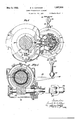
- Fig. l is a side elevation, partly in section, of one form of drive.
- Fig. 2 is a section on theline II-II of Fig. 1.
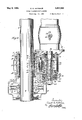
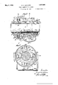
- Fig. 3 is Aa section of a different form of drive, taken on the line III-III of Figs. 4 and 5,
- Fig. 4 is a cross section on the line IV-IV of Fig. 3, and
- Fig. 5 is a cross section on the line V-V of Fig.y 3.
- Figs. l and 2 illustrate a form of driveV similar to that illustrated in ⁇ Figs. 4, 5 and 6 of the above mentioned patent specification.
- the vehicle axle l which may be a rough axle, carries a rubber sleeve 2 upon which, in turn, a pinion 3 is mounted. Both the rubber sleeve 2 and the pinion 3 are split lengthwise into two parts which are clamped together in the following manner: The hub portions of the two halves of the pinion 3 are extended on either side of the 'toothed portion thereof, one sideof the extended hub being formed with a grooved annular enaround the split sleeve 2; relative lengthwise f ⁇ movement between thepinion 3 and sleeve 2,
- the pinion may have a diameter which is very little largerv than that of the hub.
- a drive is transmitted from the axle 1 to the pinion 3 not through the rubber sleeve 2 but through a universal coupling of the kind shown in Figs. 4 and 5 of patent specification hereinbefore referred to.
- the couplin com rises a split driving ring 10 clampe on tiie axlef1, outwardly directed pins 11 mounted or formed on said ring at diametrically opposite points an oblong gimbal rin 12 provided at diametrically opposite endqs with eyelets 13 in which the pins 11 are radially slidable, outwardly directed ins 14 mounted or formed on the flat sides o the gimbal ring 12 and provided with friction reducing rotatable sleeves 15, and forked arms 16 on the hub enlargement 6 between which the pins 14 can move radially and axially of the axle 1.
- the coupling is encased by the housing 7 which has a dust tight closure 17 at
- the hub extensions of the pinion 3 are journa'lled in bushings 18 of bearing metal in a non-rotatable casing 19.
- Said pinion meshes with a pinion 20 rotatable about a shaft 21 mounted in a further casing ⁇ 22 to which the casing 19 is bolted.
- the pinion 20 theextension 27 having a journal bearing at 28 in the casing 22.
- the hubextension 27 is provided with a terminal flange 29 between which and said bearing the expansible elements 30 of a centrifugal clutch are dis osed.
- These elements four in number, ta e the form of shallow segmental shoes with tapered ends 31, the outer cylindrical surfaces of the shoes being fitted with pads 32 of friction material.
- the inner surface of each shoe 30 comprises a central hump 33 merging at each of the tapered ends into a concave surface 34.
- the driving member consists of a. substantially square formation 35 on the hub extension 27, a protrud ing circular elevation 36 being provided at each corner .of the square.
- the four elevations 36 are thus separated by four shallow recesses 37 for the reception of the convex humps 33 of the four shoes 30.
- Each of the humps 33 is longitudinally grooved at 38 for engagement with a rib 39 formed on the driving part 35V in the respective shallow recess 37, this engagement serving to keep the shoes 30 to their track within the clutch drum 40.
- Each of the shoes 30 has a recess 41 on the side nearer the flange 29 and each recess 41 is engaged by a shoe-positioning pin 42 extending laterally thereinto from said flange.
- the pins 42 have ample clearance in the recesses 41 'so as to permit not only of outward and inward movements of the shoes 30 but also of limited rocking or circular movements thereof.
- the shoes 30 On the nopposite sides the shoes 30 have arcuate rooves 43 for receiving an arc of a coil-spring ring 44 which tends always to contract the shoes around the driving part 35.
- the clutch drum 40 is integral with a sleeve 45 keyed to the shaft 25 and secured thereon by nuts 46. As may be seen from Fig. 2 the various clutch parts are housed within said drum 40 the open end of which is closed, apart from a slight clearance, by a cover 47 secured to the-casing 22.
- the casing 22 supports a ball bearing 48 for the dynamo shaft 26 and is rigidly bolted to the casing 49 of the dynamo. As illustrated more clearly in Fig. 1 the dynamo is suspended from the vehicle frame 50 by a link 51 both ends of which are litted with joints 52 providing a limited degree of universal motion.
- clutch shoes 30 may be made 1n two parts, an outer part carrying the friction pad 32 and an inner part upon which the elevation 33 is formed. These two parts may then be connected by means of a member made of a readily fusible metal. ⁇ With this arrangement evolution of heat resultant upon abnormal conditions in the-drive, for example undue slip in the clutch, will melt the fusible members and disconnect the two parts of the clutch shoes, thereby restricting the damage to the said shoes. ⁇
- lgs 3, i and 5 illustrate the application of the features of this invention to a type of drive employing a worm and worm wheelin place of the pinion transmission of Figs. 1 and 2.
- IThe split worm Wheel 3 is clamped, similarly to the pinion 3, over a rubber sleeve 2 on the axle 1 by means of the split clamping ring 5 and split casing 7.
- the universal coupling whereby axlerotation is communicated to the wheel 3 is of a modified construction, the gimbal ring being effectively re placed by a pair of arms 12 which extend around 'the shaft about diametrically opposite arcs of 900 and are each provided at one end with an eyelet 13 slidable radially on a in l1 on the clamping ring 10 and at the ot er end with a pin 14, l5 movable, both radially and axially of the axle 1, in a fork 16 on the hub extension 6 of the worm wheel 3'.
- the latterends of the arms 12 are guided tangentially of the clam ing ring 10 in grooves l53 in the said ring.
- the worm wheel 3 drives a quick pitch worm 54 on a shaft 55 at right angles to the axle 1.-
- This shaft is journalled in a casing 56 attached to the casing 19 around the gear wheelv 3 and is connected toa transmission shaft 57 extending longitudinally of the veliicle by a universal joint 58.
- the shaft 57 is connected by a second universal joint (not shown) to a shaft section carrying the ex- I pansible elements of a centrifugal clutch device through which thedynamo or other piece of apparatus is driven.
- This clutch device may be of the type described above with reference to Figs. 1 and 2.
- the casing 19 nis not supported directly from the vehicle frame but from the axle 1 through the rubber sleeve 2, the wheel 3 and bearing 18.
- Torque -in the casing 19 is taken up by an arm 59 connected by a link 51 and universal joints 52 to the vehicle frame 50.
- Vi. Transmission gearing comprising an automatic clutch device consisting of a driving part, a driven part external to said driving part, shallowl ⁇ segmental shoes operatively associated with the driving part and centrit ugally expansible into clutching engagement with the driven part, cam-like elevations on the inner sides of said shoes, and complemenm tary cam means located on the driving part 4.
- an automatic clutch device consisting of a driving part, a driven part external to said driving part, shallowl ⁇ segmental shoes operatively associated with the driving part and centrit ugally expansible into clutching engagement with the driven part, cam-like elevations on the inner sides of said shoes, and complemenm tary cam means located on the driving part 4.
- Transmission gearing for use in conjunction with anaxle of a railway vehicle, comprising in combination, a centrifugal clutch, a divided gear-wheel, a 'universal coupling connecting said gear-wheel and said axle and located laterally, a mounting for said gear-wheel consisting of a resilient sleeve embracing the axle, and annular clamping means encircling the lgear-wheel for clampin together the parts thereof over said resilient sleeve.
- Mechanism for' transmitting power from a running axle to a driven apparatus comprising in combination, mashed wheel gearing including an annular driving gear surrounding the axle anda gear loose on the s indle of the driven apparatus, a resilient s eevemounting between said axle and annular gear, a universal coupling between the axle and said annular gear, a hub revoluble with the said loose gear, a drum fixedly mounted on the spindle of the apparatus, centrifugal shoes guided on said hub and adapted for flying out into gripping engagement with said drum when the loose gear revolves with appropriate speed, and cam means on said hub adapted for engaging said shoes to augment the centrifugal gripping action.
- Transmission gearing for use in conjunction with an axle of a railway vehicle comprising in' combination, a driving gear- Wheel, a universal coupling connecting said aXle and gear-Wheel and located laterally of said gear-wheel, and a mounting for said gear-Wheel consisting of a resilient sleeve disposed between it and the axle, the transmission gearing being supported, at least in part, i
- Transmission gearing for useK in conjunction With an axle of a railway vehicle comprising in combination, a divided gear- Wheel, a universal coupling connecting said gear-Wheel and said axle and located laterally of the former, a. mounting for said gear- Wheel consisting of a resilient sleeve embracing the axle, and annular clamping means encircling the gear-Wheel for clamping together the parts thereof over said resilient sleeve.
Landscapes
- Engineering & Computer Science (AREA)
- Transportation (AREA)
- Mechanical Engineering (AREA)
- One-Way And Automatic Clutches, And Combinations Of Different Clutches (AREA)
Description
A May 3,1932?` -E. c. HTCHERL. l 1,857,020Y
.POWER TRANSMISSION GEARING" Filed Aug. 2d, 1930 3 Sheets-Sheet 1 May 3, 1932. E. c. HATCHER POWER TRANSMISSION GEARING Filed Aug. 2o, 195o 3 Sheets-Sheet 2 Filed Aug'. 20, 1930 3 Sheets-Sheet 3 Mzzl@ Patented May 3, 1932 JNTED STATES PATENT ori-ICE ERNEST CHARLES HATCHER, F NORTHWOOD, ENGLAND, ASSIGNOR TO J. STONE COM- PANY LIMITED, F DEPTFORD, ENGLAND, A GOMPANY 0F ENGLAND POWER TRANSMISSION GEARING Application filed August 20, 1930, Serial No. 476,587, and in Great Britain September 9, 1929.
T his invention ,comprises improvements in and connected with power transmission gearing, for instance for the running axles of vehicles and particularly the axles of railway vehicles. ln the specification of Patent No. 1,772,748 I have described and claimed transmission gearing for driving dynamos and other apparatus from running axles of vehicles comprising in combination a posiw tive gearing such as toothed or chaingearing and a centrifugal clutch, the centrifugal .members of the clutch being adapted for releasing the driven spindle when the axle speed falls. One object of the present imm proveniente is to obtain a dri-ving grip in the clutch which is greater and prompter in action than that obtained when thel centrifugal members are radially in guides and effect a driving grip mainly by centrifugal gc action.
According to the present improvements, in a centrifugal clutch device the centrifugal clutch members are so adapted that they undergo a camming or wedging action by the driving member when they grip the driven member, so that the centrifugal action is operative mainly for initiating the grip and the mechanical camming or Wedging action is operative for binding the centrifu- 36 gal members tightly against the driven member for transmission of the drive.
According to a further feature of this invention the driving gear wheel is elastically mounted upon the vehicle axle with the aid of an interposed rubber or like resilient sleeve. With this arrangement not only the driving gear wheel but also associated parts and their casings, for example the universal coupling, transmission gear and clutch device, may be supported solely by the resilient sleeve. A torque member is provided to prevent the mechanism rotating around the axle, said member being adapted not to interfere with the action of the universal coupling.
As there is no annular air clearance between the interior of the hub of the gear wheel and the axle, this arrangement obvi ates the large clearance which sometimes had to be provided in the case of rolling stock required to travel over rough roads or tracks lest the gear wheel should strike the axle and be damaged by the impact. It is desirable moveover to keep thel diameter of the driving gear wheel as small as possible in view of the necessary clearance between said wheel coach. In order to accommodate the bolts,
the gear wheel must be made of. a larger diameter than it need be if such bolts were absent. As stated it is desirable to use gear Wheels as small as possible so as to leave as much clearance as possible between them and the roadway or track. According to a fur ther feature of these improvements, the parts of a gear wheel ofI the kind in question are fastened together around the axle by clampn ing means encircling such parts.
Two embodiments of the invention are i1- lustrated by way of example in the accompanyiug drawings, in which Fig. l isa side elevation, partly in section, of one form of drive. A
Fig. 2 is a section on theline II-II of Fig. 1.
Fig. 3 is Aa section of a different form of drive, taken on the line III-III of Figs. 4 and 5,
Fig. 4 is a cross section on the line IV-IV of Fig. 3, and
Fig. 5 is a cross section on the line V-V of Fig.y 3.
Figs. l and 2 illustrate a form of driveV similar to that illustrated in` Figs. 4, 5 and 6 of the above mentioned patent specification. The vehicle axle l, which may be a rough axle, carries a rubber sleeve 2 upon which, in turn, a pinion 3 is mounted. Both the rubber sleeve 2 and the pinion 3 are split lengthwise into two parts which are clamped together in the following manner: The hub portions of the two halves of the pinion 3 are extended on either side of the 'toothed portion thereof, one sideof the extended hub being formed with a grooved annular enaround the split sleeve 2; relative lengthwise f `movement between thepinion 3 and sleeve 2,
is prevented by shoulders 9 on the latter and relative such movement between the parts of the 'pinion 3 and between'the pinion 3 and the clamping means 5, 7 is prevented by ribs 5', 7 on said means engaging the grooves in the" enlar ements 4, 6. Owing to the absence of bo ts within the periphery of the pinion 3 for bolting the parts thereof together, the pinion may have a diameter which is very little largerv than that of the hub.
A drive is transmitted from the axle 1 to the pinion 3 not through the rubber sleeve 2 but through a universal coupling of the kind shown in Figs. 4 and 5 of patent specification hereinbefore referred to. As the action of such couplings is fully described in that 'speciication, it may be briefly stated that the couplin com rises a split driving ring 10 clampe on tiie axlef1, outwardly directed pins 11 mounted or formed on said ring at diametrically opposite points an oblong gimbal rin 12 provided at diametrically opposite endqs with eyelets 13 in which the pins 11 are radially slidable, outwardly directed ins 14 mounted or formed on the flat sides o the gimbal ring 12 and provided with friction reducing rotatable sleeves 15, and forked arms 16 on the hub enlargement 6 between which the pins 14 can move radially and axially of the axle 1. The coupling is encased by the housing 7 which has a dust tight closure 17 at the outer end.
The hub extensions of the pinion 3 are journa'lled in bushings 18 of bearing metal in a non-rotatable casing 19. Said pinion meshes with a pinion 20 rotatable about a shaft 21 mounted in a further casing `22 to which the casing 19 is bolted. The pinion 20 theextension 27 having a journal bearing at 28 in the casing 22. i
0n the far side of this bearing 28 the hubextension 27 is provided with a terminal flange 29 between which and said bearing the expansible elements 30 of a centrifugal clutch are dis osed. These elements, four in number, ta e the form of shallow segmental shoes with tapered ends 31, the outer cylindrical surfaces of the shoes being fitted with pads 32 of friction material. The inner surface of each shoe 30 comprises a central hump 33 merging at each of the tapered ends into a concave surface 34. The driving member consists of a. substantially square formation 35 on the hub extension 27, a protrud ing circular elevation 36 being provided at each corner .of the square. The four elevations 36 are thus separated by four shallow recesses 37 for the reception of the convex humps 33 of the four shoes 30. Each of the humps 33 is longitudinally grooved at 38 for engagement with a rib 39 formed on the driving part 35V in the respective shallow recess 37, this engagement serving to keep the shoes 30 to their track within the clutch drum 40.
Each of the shoes 30 has a recess 41 on the side nearer the flange 29 and each recess 41 is engaged by a shoe-positioning pin 42 extending laterally thereinto from said flange. The pins 42 have ample clearance in the recesses 41 'so as to permit not only of outward and inward movements of the shoes 30 but also of limited rocking or circular movements thereof. On the nopposite sides the shoes 30 have arcuate rooves 43 for receiving an arc of a coil-spring ring 44 which tends always to contract the shoes around the driving part 35. The clutch drum 40 is integral with a sleeve 45 keyed to the shaft 25 and secured thereon by nuts 46. As may be seen from Fig. 2 the various clutch parts are housed within said drum 40 the open end of which is closed, apart from a slight clearance, by a cover 47 secured to the-casing 22.
The casing 22 supports a ball bearing 48 for the dynamo shaft 26 and is rigidly bolted to the casing 49 of the dynamo. As illustrated more clearly in Fig. 1 the dynamo is suspended from the vehicle frame 50 by a link 51 both ends of which are litted with joints 52 providing a limited degree of universal motion.
The operation of a drive of this nature is as follows Rotation of the vehicle axle 1 is transmitted from the ring 10 through the coupling 11-16to the gear wheel 3, whencfl a drive is transmitted through the gear wheels 20, 23 to the hub extension 27. Assume that the axle 1 is accelerating after llo' being at rest: The centrifugal force on the shoes 30 is insuiiicient to throw them out against the resistancel of the spring 44 and consequently the hub Aextension 27, the driving part 35 and flange ,29`thereon,` and the shoes 30 rotate idly together. When the axle speed lis such that the shoes 30 come into frictional contact with the stationary drum 40, said shoes immediately suffer a retardation in relation to the driving part 35 the elevations 36 on which engage against one or other of the concave cam surfaces 33 on each of the shoes 3U and,owing to the cam effect, press the latter forcibly against the interior of the clutch-drum, producing amember 35. The friction between the drum and shoes will release the latter from the driving member leaving said shoes free to becontracted bythe spring 44.
In contradistinction to the arrangement described in the above mentioned prior specication neither of the casings 19 or 22 is mounted on the vehicle frame. Instead the gear wheel 3 is mounted on the' axle 1 by means of the rubber sleeve 2 and the casings p 19, 22 are supported partly .by the axle 4dynamo suspension 50-52 which is esi sibly of other parts of the apparatus, the
The worm wheel 3 drives a quick pitch worm 54 on a shaft 55 at right angles to the axle 1.- This shaft is journalled in a casing 56 attached to the casing 19 around the gear wheelv 3 and is connected toa transmission shaft 57 extending longitudinally of the veliicle by a universal joint 58. The shaft 57 is connected by a second universal joint (not shown) to a shaft section carrying the ex- I pansible elements of a centrifugal clutch device through which thedynamo or other piece of apparatus is driven. This clutch device may be of the type described above with reference to Figs. 1 and 2.
As in the gear of Figs. l and 2, the casing 19nis not supported directly from the vehicle frame but from the axle 1 through the rubber sleeve 2, the wheel 3 and bearing 18. Torque -in the casing 19 is taken up by an arm 59 connected by a link 51 and universal joints 52 to the vehicle frame 50.
Vil. Transmission gearing comprising an automatic clutch device consisting of a driving part, a driven part external to said driving part, shallowl` segmental shoes operatively associated with the driving part and centrit ugally expansible into clutching engagement with the driven part, cam-like elevations on the inner sides of said shoes, and complemenm tary cam means located on the driving part 4.
and operative upon said elevations for augmenting the centrifugal clutching effect.
2. Transmission gearing for use in conjunction with anaxle of a railway vehicle, comprising in combination, a centrifugal clutch, a divided gear-wheel, a 'universal coupling connecting said gear-wheel and said axle and located laterally, a mounting for said gear-wheel consisting of a resilient sleeve embracing the axle, and annular clamping means encircling the lgear-wheel for clampin together the parts thereof over said resilient sleeve.
3. Mechanism for' transmitting power from a running axle to a driven apparatus comprising in combination, mashed wheel gearing including an annular driving gear surrounding the axle anda gear loose on the s indle of the driven apparatus, a resilient s eevemounting between said axle and annular gear, a universal coupling between the axle and said annular gear, a hub revoluble with the said loose gear, a drum fixedly mounted on the spindle of the apparatus, centrifugal shoes guided on said hub and adapted for flying out into gripping engagement with said drum when the loose gear revolves with appropriate speed, and cam means on said hub adapted for engaging said shoes to augment the centrifugal gripping action.
4. Transmission gearing for use in conjunction with an axle of a railway vehicle comprising in' combination, a driving gear- Wheel, a universal coupling connecting said aXle and gear-Wheel and located laterally of said gear-wheel, and a mounting for said gear-Wheel consisting of a resilient sleeve disposed between it and the axle, the transmission gearing being supported, at least in part, i
from the axle by the resilient sleeve.
5. Transmission gearing for useK in conjunction With an axle of a railway vehicle, comprising in combination, a divided gear- Wheel, a universal coupling connecting said gear-Wheel and said axle and located laterally of the former, a. mounting for said gear- Wheel consisting of a resilient sleeve embracing the axle, and annular clamping means encircling the gear-Wheel for clamping together the parts thereof over said resilient sleeve.
ERNEST CHARLES HATCHER.
Applications Claiming Priority (1)
| Application Number | Priority Date | Filing Date | Title |
|---|---|---|---|
| GB1857020X | 1929-09-09 |
Publications (1)
| Publication Number | Publication Date |
|---|---|
| US1857020A true US1857020A (en) | 1932-05-03 |
Family
ID=10892121
Family Applications (1)
| Application Number | Title | Priority Date | Filing Date |
|---|---|---|---|
| US476587A Expired - Lifetime US1857020A (en) | 1929-09-09 | 1930-08-20 | Power transmission gearing |
Country Status (1)
| Country | Link |
|---|---|
| US (1) | US1857020A (en) |
Cited By (4)
| Publication number | Priority date | Publication date | Assignee | Title |
|---|---|---|---|---|
| US2599793A (en) * | 1946-09-25 | 1952-06-10 | Borg Warner | Sprag type clutch |
| US2632404A (en) * | 1948-11-26 | 1953-03-24 | Woolery Machine Company | Self-propelled railway maintenance car |
| US2825437A (en) * | 1954-09-07 | 1958-03-04 | Koren Res & Engineering Compan | Coupling apparatus |
| US4591349A (en) * | 1983-06-15 | 1986-05-27 | Steyr-Daimler-Puch Aktiengesellschaft | Cardan shaft drive for a transmission, particularly for the distribution transmission of a motor vehicle with all-wheel drive |
-
1930
- 1930-08-20 US US476587A patent/US1857020A/en not_active Expired - Lifetime
Cited By (4)
| Publication number | Priority date | Publication date | Assignee | Title |
|---|---|---|---|---|
| US2599793A (en) * | 1946-09-25 | 1952-06-10 | Borg Warner | Sprag type clutch |
| US2632404A (en) * | 1948-11-26 | 1953-03-24 | Woolery Machine Company | Self-propelled railway maintenance car |
| US2825437A (en) * | 1954-09-07 | 1958-03-04 | Koren Res & Engineering Compan | Coupling apparatus |
| US4591349A (en) * | 1983-06-15 | 1986-05-27 | Steyr-Daimler-Puch Aktiengesellschaft | Cardan shaft drive for a transmission, particularly for the distribution transmission of a motor vehicle with all-wheel drive |
Similar Documents
| Publication | Publication Date | Title |
|---|---|---|
| CN105992886B (en) | Drive for a dog clutch and method of controlling the drive | |
| US1857020A (en) | Power transmission gearing | |
| US2038450A (en) | Power-transmission mechanism | |
| US2235002A (en) | Universal joint | |
| US2122837A (en) | Universal coupling | |
| US2340415A (en) | Centrifugal clutch | |
| US3078972A (en) | Power transmissions | |
| US2334221A (en) | Power transmission apparatus | |
| US2329075A (en) | Torque dividing mechanism | |
| US2349388A (en) | Steering drive axle | |
| US2487485A (en) | Universal coupling | |
| US1583291A (en) | Propeller shaft | |
| US2042404A (en) | Steering wheel drive for vehicles | |
| US1271424A (en) | Friction-clutch. | |
| US6318535B1 (en) | Arrangement for transferring braking torques in motor vehicles | |
| US3381152A (en) | Foucault current braking devices | |
| US1440575A (en) | Clutch | |
| US1207767A (en) | Clutch mechanism. | |
| US3169618A (en) | Centrifugally actuated clutch | |
| US1520336A (en) | Coupling | |
| US2019367A (en) | Overrunning gearless differential | |
| US1223924A (en) | Power-transmitting mechanism. | |
| US1823912A (en) | Clutch | |
| US1017407A (en) | Transmission mechanism for automobiles. | |
| US1492536A (en) | Clutch |