US1856966A - Pipe drawing and holding device - Google Patents
Pipe drawing and holding device Download PDFInfo
- Publication number
- US1856966A US1856966A US390692A US39069229A US1856966A US 1856966 A US1856966 A US 1856966A US 390692 A US390692 A US 390692A US 39069229 A US39069229 A US 39069229A US 1856966 A US1856966 A US 1856966A
- Authority
- US
- United States
- Prior art keywords
- pipe
- gripping member
- holding
- outwardly
- holding device
- Prior art date
- Legal status (The legal status is an assumption and is not a legal conclusion. Google has not performed a legal analysis and makes no representation as to the accuracy of the status listed.)
- Expired - Lifetime
Links
Images
Classifications
-
- B—PERFORMING OPERATIONS; TRANSPORTING
- B25—HAND TOOLS; PORTABLE POWER-DRIVEN TOOLS; MANIPULATORS
- B25B—TOOLS OR BENCH DEVICES NOT OTHERWISE PROVIDED FOR, FOR FASTENING, CONNECTING, DISENGAGING OR HOLDING
- B25B27/00—Hand tools, specially adapted for fitting together or separating parts or objects whether or not involving some deformation, not otherwise provided for
- B25B27/02—Hand tools, specially adapted for fitting together or separating parts or objects whether or not involving some deformation, not otherwise provided for for connecting objects by press fit or detaching same
- B25B27/06—Hand tools, specially adapted for fitting together or separating parts or objects whether or not involving some deformation, not otherwise provided for for connecting objects by press fit or detaching same inserting or withdrawing sleeves or bearing races
-
- B—PERFORMING OPERATIONS; TRANSPORTING
- B25—HAND TOOLS; PORTABLE POWER-DRIVEN TOOLS; MANIPULATORS
- B25B—TOOLS OR BENCH DEVICES NOT OTHERWISE PROVIDED FOR, FOR FASTENING, CONNECTING, DISENGAGING OR HOLDING
- B25B27/00—Hand tools, specially adapted for fitting together or separating parts or objects whether or not involving some deformation, not otherwise provided for
- B25B27/14—Hand tools, specially adapted for fitting together or separating parts or objects whether or not involving some deformation, not otherwise provided for for assembling objects other than by press fit or detaching same
- B25B27/30—Hand tools, specially adapted for fitting together or separating parts or objects whether or not involving some deformation, not otherwise provided for for assembling objects other than by press fit or detaching same positioning or withdrawing springs, e.g. coil or leaf springs
- B25B27/302—Hand tools, specially adapted for fitting together or separating parts or objects whether or not involving some deformation, not otherwise provided for for assembling objects other than by press fit or detaching same positioning or withdrawing springs, e.g. coil or leaf springs coil springs other than torsion coil springs
- B25B27/304—Hand tools, specially adapted for fitting together or separating parts or objects whether or not involving some deformation, not otherwise provided for for assembling objects other than by press fit or detaching same positioning or withdrawing springs, e.g. coil or leaf springs coil springs other than torsion coil springs by compressing coil springs
-
- Y—GENERAL TAGGING OF NEW TECHNOLOGICAL DEVELOPMENTS; GENERAL TAGGING OF CROSS-SECTIONAL TECHNOLOGIES SPANNING OVER SEVERAL SECTIONS OF THE IPC; TECHNICAL SUBJECTS COVERED BY FORMER USPC CROSS-REFERENCE ART COLLECTIONS [XRACs] AND DIGESTS
- Y10—TECHNICAL SUBJECTS COVERED BY FORMER USPC
- Y10T—TECHNICAL SUBJECTS COVERED BY FORMER US CLASSIFICATION
- Y10T29/00—Metal working
- Y10T29/53—Means to assemble or disassemble
- Y10T29/53613—Spring applier or remover
- Y10T29/53622—Helical spring
Definitions
- the present invention relates to devices for drawing pipes or tubular bodies longitudinally and holding the same against longitudinal movement; and its object is to provide an improved device of that character which shall be simple and economical in construction and efficient in operation.
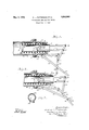
- Figure 1 is a side view of a pipe drawing and holding device applied to the tubular piston rod of an air brake cylinder, certain parts being shown in axial section;
- Figure 2 is a like view of the same, but showing the parts in another position, and
- Figure 3 is a transaxial view of the piston l rod and an end view of said clamp applied thereto.
- the object of the present invention is to obviate or minimize such diiiiculty.
- our device is shown applied to the hollow or tubular piston rod 1 of the piston 2 in an air brake cylinder having a head 3 detachably secured to the body portion 4 of the cylinder by the screw bolts 5.
- This piston is pressed away from said head by a stiff coiled spring 6 surrounding the piston rod.
- the end 7 of the piston rod somey times projects outwardly from the cylinder' head only a short distance (as seen in Figure 1) so that it is diicult to apply tosaid projecting end a clamp (such, for instance, as is shown in Figure 3) to hold the piston against the expansive force of said spring while removing the cylinder head and with it the G, 132sserial No. 390,692.-
- our device comprises two principal portions, a gripping member, and drawing or holding members.
- the gripping member of the device is an elongated bar 8 longer than the internal width or diameter of the pipe (in this lcase the tubular piston rod 1), so that said bar may be swung from a position wherein it may be readily inserted into the pi e to a more nearly right angled position re atively to the pipes axis, thus to cause the ends 9, 9 of this bar 8 to holdingly engage or grip the pipes internal surface at .opposite points.
- the drawingand holding member or members of the device .operate to thus swing the grippingvmember into its operative position to hold the pipe in its -tlien position, and thereupon to draw the pipe outwardly against the pressure of the spring ⁇ 6.
- These holding and drawing members comprise a pair of parallelly disposed rods'lO, 11 whose spaced-apart innerends are pivotaly connected at 12, 13 respectively to the gripping member, these connections 12, 13 being on the opposite sides of .(i. e. spaced oppositely and .outwardly from) the middle point of the gripping member.
- the spaced,- apart outer ends 0f these reds are pvota'lly connected L14., l5 respectively :to the swingable arm 16 ,adjacent one .end thereof, the other end of this arm beine' pivotallr 00n- Ilected 4at 17 :to a lever ,18 'fillrumed at 1.9
- This movement of said arm causes ,the frods 1-0, 1 1to spread apart, thereby causing the gripping member to swing to a position (seen in Fig. 2) more nearly at right angles to the pipes axis so that the ends 9, 9 of the gripping member engage and bite into the inner surface of the pipe, these ends being oppositely curved as shown to facilitate this movement.
- the holding and drawing device may now be removed from engagement with the inner surface of the pipe or piston rod, the bolts 5 removed, and the cylinder head 3 and the piston 2 and spring 6 with it removed from the cylinder.
- An arm 25 pivoted at 26 on the fulcrum member 20 and having a stop notch 27 engaging the levers projection 28 may he provided to hold the lever in its outwardly swung operative position.
- a device for drawing a pipe longitudinally and holding the same against longitudinal movement comprising: a gripping member longer than the pipes internal width and adapted to be swung to a position wherein its ends operatively engage the pipes internal surface; a pair of rods pivotally connected at their spaced apart inner ends to the gripping member a fulcrum member a lever fulcrumed thereon; a link pivotally connected at one end to the lever and adjacent its other end pivotally connected to the spaced apart outer ends of the rods.
- a device for drawing a pipe longitudinally and holding the same against longitudinal movement comprising: a gripping member longer than the pipes internal width and adapted to be swung to a position wherein its ends operatively engage the pipes internal surface; a pair of rods pivotally connected at their spaced apart inner ends to the gripping member; a fulcrum member; a lever fulcrumed thereon; a link pivotally connected at one end to the lever and adjacent its other end pivotally connected to the spaced apart outer ends of the rods; an arm pivotally connected to the fulcrum member and having a stop adapted to engage the lever to hold the same in its operative position.
Landscapes
- Engineering & Computer Science (AREA)
- Mechanical Engineering (AREA)
- Load-Engaging Elements For Cranes (AREA)
Description
May', 1932. H. l.. PATTERSON En' AL' 1,856,966
PIPE DRAWING AND HOLDING DEVICE Filed Sept'. 6, 1929 Patented May 3, 1932 UNITED STATES PATENT OFFICE HARVEY L. PATTERSON, E GRAND RAPIDsAND How-ARD J, Qualen,
TOWNSHIP, KENT COUNTY. MlQllGAN PIPE DRAWING AND nonnina' nEvrcE l Application led September The present invention relates to devices for drawing pipes or tubular bodies longitudinally and holding the same against longitudinal movement; and its object is to provide an improved device of that character which shall be simple and economical in construction and efficient in operation.
This and any other and more specic objects hereinafter appearing are attained by, and the invention finds preferable embodiment in, the device hereinafter particularly described in the body of this speciiication and illustrated by the accompanying drawings, in which:
Figure 1 is a side view of a pipe drawing and holding device applied to the tubular piston rod of an air brake cylinder, certain parts being shown in axial section;
Figure 2 is a like view of the same, but showing the parts in another position, and
a clamp applied to the outwardly drawn piston rod; and
Figure 3 is a transaxial view of the piston l rod and an end view of said clamp applied thereto.
Great diliculty is experienced in drawing longitudinally a pipe or tubular body and in holding the same in drawn position, particularly where the pipe must be drawn and held against the pressure of a sti spring as in the case of an air-brake cylinders tubular piston rod.
The object of the present invention is to obviate or minimize such diiiiculty. In the embodiment of the invention illustrated by these drawings, our device is shown applied to the hollow or tubular piston rod 1 of the piston 2 in an air brake cylinder having a head 3 detachably secured to the body portion 4 of the cylinder by the screw bolts 5.
This piston is pressed away from said head by a stiff coiled spring 6 surrounding the piston rod. The end 7 of the piston rod somey times projects outwardly from the cylinder' head only a short distance (as seen in Figure 1) so that it is diicult to apply tosaid projecting end a clamp (such, for instance, as is shown in Figure 3) to hold the piston against the expansive force of said spring while removing the cylinder head and with it the G, 132sserial No. 390,692.-
piston from the cylinder for repairs, cleaning, ete. lIt sometimes happens that on removing the bolts 5 the piston headis suddenly thrown outwardly by the spring 6 thus eri'- da-ngering the workmen employed in this work.
Our device comprises two principal portions, a gripping member, and drawing or holding members. In the illustrated construction the gripping member of the device is an elongated bar 8 longer than the internal width or diameter of the pipe (in this lcase the tubular piston rod 1), so that said bar may be swung from a position wherein it may be readily inserted into the pi e to a more nearly right angled position re atively to the pipes axis, thus to cause the ends 9, 9 of this bar 8 to holdingly engage or grip the pipes internal surface at .opposite points. The drawingand holding member or members of the device .operate to thus swing the grippingvmember into its operative position to hold the pipe in its -tlien position, and thereupon to draw the pipe outwardly against the pressure of the spring `6.
i These holding and drawing members comprise a pair of parallelly disposed rods'lO, 11 whose spaced-apart innerends are pivotaly connected at 12, 13 respectively to the gripping member, these connections 12, 13 being on the opposite sides of .(i. e. spaced oppositely and .outwardly from) the middle point of the gripping member. The spaced,- apart outer ends 0f these reds are pvota'lly connected L14., l5 respectively :to the swingable arm 16 ,adjacent one .end thereof, the other end of this arm beine' pivotallr 00n- Ilected 4at 17 :to a lever ,18 'fillrumed at 1.9
0.11 a .strut .or .fulcrum member ,2.0 `salted at' its other @M121 on ,the , flange 2,2 of `.the .cylinder head, Y
The rods l0., ,1.1 ,beine .moved 4ttuvalfd .each other sufficiently, their inner .ends and the gripping member Searried thereby are thrust into'the vpipe (the tubular piston rod 1). The fulcrum member 20 beifng seated 'on the fia-nge 22,-the `leve- r 1,8 is swung outwardly (in the direction of the arrow) thereby swinging the arm 16 ,also outwardly. This movement of said arm causes ,the frods 1-0, 1 1to spread apart, thereby causing the gripping member to swing to a position (seen in Fig. 2) more nearly at right angles to the pipes axis so that the ends 9, 9 of the gripping member engage and bite into the inner surface of the pipe, these ends being oppositely curved as shown to facilitate this movement.
It will be seen that this movement of the lever 18 and arm 16 first causes the rods 10, 11 to move longitudinally in opposite directions relatively to each other, and then, when the gripping member 8 operatively engages the pipe, draws the same outwardly to such position (as seen in Figure 2) that a split ring clamp 23 shown in Figure 3 may be placed around the pipe 1 and drawn by its screw 24 into clamping relation therewith, the clamps inner edge abutting on the outer extremity of the cylinder head 3 as shown in Figure 2.
`The holding and drawing device may now be removed from engagement with the inner surface of the pipe or piston rod, the bolts 5 removed, and the cylinder head 3 and the piston 2 and spring 6 with it removed from the cylinder. An arm 25 pivoted at 26 on the fulcrum member 20 and having a stop notch 27 engaging the levers projection 28 may he provided to hold the lever in its outwardly swung operative position.
The invention being int-ended to be pointed out in the claims, is not to be limited to or by details of construction of the particular embodiment thereof illustrated by the drawings or hereinbefore described.
We claim:
1. A device for drawing a pipe longitudinally and holding the same against longitudinal movement, comprising: a gripping member longer than the pipes internal width and adapted to be swung to a position wherein its ends operatively engage the pipes internal surface; a pair of rods pivotally connected at their spaced apart inner ends to the gripping member a fulcrum member a lever fulcrumed thereon; a link pivotally connected at one end to the lever and adjacent its other end pivotally connected to the spaced apart outer ends of the rods.
2. A device for drawing a pipe longitudinally and holding the same against longitudinal movement, comprising: a gripping member longer than the pipes internal width and adapted to be swung to a position wherein its ends operatively engage the pipes internal surface; a pair of rods pivotally connected at their spaced apart inner ends to the gripping member; a fulcrum member; a lever fulcrumed thereon; a link pivotally connected at one end to the lever and adjacent its other end pivotally connected to the spaced apart outer ends of the rods; an arm pivotally connected to the fulcrum member and having a stop adapted to engage the lever to hold the same in its operative position.
In testimony whereof we have hereunto set our hands at Grand Rapids, Michigan, this 30th day of August, 1929.
HARVEY L. PATTERSON. HOWARD J. QUAIFE.
ves
Priority Applications (1)
| Application Number | Priority Date | Filing Date | Title |
|---|---|---|---|
| US390692A US1856966A (en) | 1929-09-06 | 1929-09-06 | Pipe drawing and holding device |
Applications Claiming Priority (1)
| Application Number | Priority Date | Filing Date | Title |
|---|---|---|---|
| US390692A US1856966A (en) | 1929-09-06 | 1929-09-06 | Pipe drawing and holding device |
Publications (1)
| Publication Number | Publication Date |
|---|---|
| US1856966A true US1856966A (en) | 1932-05-03 |
Family
ID=23543524
Family Applications (1)
| Application Number | Title | Priority Date | Filing Date |
|---|---|---|---|
| US390692A Expired - Lifetime US1856966A (en) | 1929-09-06 | 1929-09-06 | Pipe drawing and holding device |
Country Status (1)
| Country | Link |
|---|---|
| US (1) | US1856966A (en) |
-
1929
- 1929-09-06 US US390692A patent/US1856966A/en not_active Expired - Lifetime
Similar Documents
| Publication | Publication Date | Title |
|---|---|---|
| US2779089A (en) | Puller tool having a manually operated sliding hammer | |
| US2504152A (en) | Gripper | |
| US1519938A (en) | Flexible pliers | |
| US2374947A (en) | High pressure test plug | |
| US2381657A (en) | Work clamping mechanism | |
| US3033559A (en) | Clamp | |
| US1587689A (en) | Device for applying flexible pipe connections | |
| US1856966A (en) | Pipe drawing and holding device | |
| US2113755A (en) | Tool for pulling inside axle bearing cones | |
| US1435278A (en) | Bearing puller | |
| US1816446A (en) | Grapple | |
| US1403754A (en) | Sleeve puller | |
| US1842142A (en) | Piston gripping tool | |
| US2668511A (en) | Plumber's tool | |
| US20170209965A1 (en) | Brass Compression Ring Removal Tool | |
| US2593935A (en) | Cotter pin puller | |
| US3766810A (en) | Tie rod adjustment tool | |
| US1043400A (en) | Wheel-puller. | |
| US1267798A (en) | Device for bending pipes. | |
| US2654414A (en) | Tube expanding tool | |
| US3774288A (en) | Tool for inserting and removing parts in mechanical assemblages | |
| US2303061A (en) | Apparatus for preparing flared end | |
| US1733773A (en) | Combination vise and gripping tool | |
| US2682102A (en) | Drill pipe protector apparatus | |
| US1560280A (en) | Plumbing tool |