US1856964A - Motor vehicle - Google Patents
Motor vehicle Download PDFInfo
- Publication number
- US1856964A US1856964A US159515A US15951527A US1856964A US 1856964 A US1856964 A US 1856964A US 159515 A US159515 A US 159515A US 15951527 A US15951527 A US 15951527A US 1856964 A US1856964 A US 1856964A
- Authority
- US
- United States
- Prior art keywords
- sill
- frame
- panel
- vehicle
- sills
- Prior art date
- Legal status (The legal status is an assumption and is not a legal conclusion. Google has not performed a legal analysis and makes no representation as to the accuracy of the status listed.)
- Expired - Lifetime
Links
- 238000010276 construction Methods 0.000 description 6
- 230000005484 gravity Effects 0.000 description 5
- 239000000463 material Substances 0.000 description 5
- 230000002787 reinforcement Effects 0.000 description 3
- XEEYBQQBJWHFJM-UHFFFAOYSA-N Iron Chemical compound [Fe] XEEYBQQBJWHFJM-UHFFFAOYSA-N 0.000 description 2
- 230000004048 modification Effects 0.000 description 2
- 238000012986 modification Methods 0.000 description 2
- 230000003014 reinforcing effect Effects 0.000 description 2
- 239000002023 wood Substances 0.000 description 2
- 229910000831 Steel Inorganic materials 0.000 description 1
- 230000006835 compression Effects 0.000 description 1
- 238000007906 compression Methods 0.000 description 1
- 229910052742 iron Inorganic materials 0.000 description 1
- 239000002184 metal Substances 0.000 description 1
- 229910052751 metal Inorganic materials 0.000 description 1
- 239000010959 steel Substances 0.000 description 1
Images

Classifications
-
- B—PERFORMING OPERATIONS; TRANSPORTING
- B62—LAND VEHICLES FOR TRAVELLING OTHERWISE THAN ON RAILS
- B62D—MOTOR VEHICLES; TRAILERS
- B62D25/00—Superstructure or monocoque structure sub-units; Parts or details thereof not otherwise provided for
- B62D25/08—Front or rear portions
- B62D25/16—Mud-guards or wings; Wheel cover panels
Definitions
- This invention relates to motor vehicles and more particularly to improvements in the body and frame construction of motor vehicles.
- the chassis frame side members are provided at their rear ends, with kick-up 'portions adapted to insure a clearance for the body and frame with respect to the rear axle, wheels and differential housing.
- the body sills are ordinarily provided with similar kick-up portions, adapted to lit onto the corresponding portions ofthe frame.
- Another object is to improve the appearance of a motor vehicle.
- a still further object is to improve the body and frame construction of a motor vehicle.
- a relatedobject is to strengthen the body and frame of a motor vehicle.
- a feature of the invention' is a member adapted to provide a housing for the wheels of al motor or other vehicle, to reinforce the frame and to support the body thereof.
- a further feature is a structure, wherein a vehicle body is supported upon the lower flange of a frame member the upper flange of which has been replaced by an extension adapted to form a wheel housing
- An additional ⁇ feature is a 'vehicle body, having sills supported upona frame, and including a semi-circular recess providing a wheel housing, with a reinforcing member adapted to strengthen the body at the Vpoint of support.
- a Ystructure including a supporting frame and a vehicle body mounted thereon.
- the frame includes a member adapted to provide reinforcement therefor, to support the body and to house a wheel of the vehicle.
- the rbody includes a reinforcing member co-operating with the frame member to brace and support the body.
- the body sills arepositioned on the frame, below the upper edge thereof, to lower the center of gravity of the body.
- Fig. 2 is a view in section on lineQ-Q of Fig. l;
- Fig. 3 is a view similar to Fig. lshowing a modification of the invention
- Fig. 4 is avie'w in section on line 4-4 of Fig. 3, and
- Fig. 5 is a perspective view of the kick-up portion of the frame of Figs. ⁇ l'to 4.
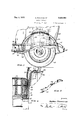
- Figs. l and2 illustrate. a part of the rear end of a motor4 vehicle including a body 10, mounted on a frame l1, 'supported by springs 12 attached to 4a'n axle, not shown, having 'wheels 13 thereon.
- the springs are 'attached to 'the frameby a front bracket 15 and Tar'e'a'r shackle l5.
- the body Vin cludes a rearfseatl of any suitable construction and side panel members 17, which may be ofrmetal; Y"lihe'fbody also includes supporting sills l4.,-one-only1of which is shown. The si-llsqr'estup on the lower flan'ge inf.
- the body panels, adjacent to the rear wheels, are formed with a semicircular recess 18 to provide sufficient clearance between the body and the wheels to allow for the movement occasioned by the springs. These recesses also make it unnecessary to limit the width of the entire rear portion of the body to the ⁇ distance between the rear wheels.
- the panel member 17 is attached, at its lower edge, to an angle-shaped member or bracket 19 which may be bolted or otherwise suitably attached to the sill 14.
- the bracket is preferably of iron and the sill of wood.
- the bracket 19 extends beyond the inner edge of the sill 14 and provides a support for the frame member 2() of the seat 16.
- the upholstery for the side of the rear seat may also be attached to the upper surface of the sill 14, in the manner illustrated.
- a lining strip 19 of webbed or other suitable material to prevent wear and noise caused by relative movement of the body and frame.
- a curved semi-circular plate 21 is attached to the web of the side frame member 11 and extends vertically and laterally therefrom. This plate provides a reinforcement for the portion of the side frame member 11 along which the upper flange has been removed. This member also functions, in co-operation with a fender, to provide a wheel housing.
- the fender 23 is attached to the member 21 and also to the body panel 17. Between the elements 21 and 17, at the point of attachment of the fender, is provided a lining strip 24 as a cushion for preventing wear and noise caused by the relative movement of the separated members.
- a curved body frame member 25 preferably of wood forms an arch extending around the wheel housing on the inside of the body panel and serves as a body support at this point.
- the body panel 17 is preferably constructed of material sufficiently strong to withstand considerable force either of compression or tension and the member 21 is likewise of relatively heavy material.
- the members 17 and 21 may be for example of steel. These members 'co-operate to reinforce and support the body 10 and fender 23 and to provide a housing for the wheel.
- the structure shown in Figs. 1 and 2 has advantages relating to improvement in the appearance and stability of the vehicle.
- the provision of a kick-up portion on the frame enables the main parts of the frame and body to be materially lowered. This results in a lowering ofthe center of gravity of the entirecar, whereby its equilibrium and appearance are improved. Ordinarily a similar kick-up portion on the body sills is required Vbody panel 17.
- the upper flange of the frame side member is removed along the kick-up to permit the body sill to rest on the lower flange.
- the sills may therefore be straight, whereby their construction is simplified.
- the structure of this invention also provides an exceedingly secure attachment of the body to the frame.
- the web of the side frame members functions to prevent sidewise movement of the body, since the body sills are positioned upon the lower flange 22.
- FIGs. 3 and 4 a modification of the structure shown in Figs. 1 and 2 is illustrated. These figures will not be described in detail, because in most respects they are substantially the same as Figs. 1 and 2.
- braces 2G are provided for supporting the body panel member 17.
- This member may therefore be constructed of light sheet metal or other suitable light material, which need not be capable of withstanding severe strain.
- the braces 26 are positioned along the inner surface of the recess 18 in the The upper ends of the braces, which extend through suitable openings 30 in the panel 17, are attached to the members 25 and their lower ends are suitably attached to the outer side of the sills 14.
- the braces 26 therefore are adapted to reinforce the body and relieve the strain on the body panel member 17
- the structure of Figs. 3 and 4 is similar to that of Figs. 1 and 2.
- the body sills 14 are supported on the lower flange 22 of the kick-up on the frame in the same manner as describedfin connection with Figs. 1 and 2, whereby straight sills may be employed, the center of gravity of the vehicle is lowered and its appearance improved.
- the semi-circular member-21 provides a reinforcement for the side of the frame member as well as a housing for the wheel and a support for the body and for the fender 23.
- a vehicle having a frame member with a portion thereof removed and a body structure including a panel, supporting sill members for said body arranged in relatively different horizontal planes, the upper sill being adapted to form a support for the panel and the lower sill being adapted to rest on the frame member at the zone of the removed portion, said body panel being secured to the lower sill, a stiifening member extending between the sills and secured at either end thereto, and a housing for a wheel of the vehicle secured at one side thereof to the frame member at the zone of the removed portionV and secured at the other side thereof to the said upper sill, said housing being adapted to reinforce the frame member at the point where it has been weakened by the removal of a portion thereof.
- a vehicle having a frame member with a portion thereof removed and a body structure including a panel, supporting sill members for said body arranged in relatively different horizontal planes, the upper sill being adapted to form a support for the panel and the lower sill being adapted to rest on the frame member at the zone of the removed portion, said body panel being secured to the lower sill, and a housing for a wheel of the vehicle secured at one side thereof to the frame member at the zone of the removed portion and secured at the other side thereof to the said upper sill, said housing being adapted to reinforce the frame member at the point where it has been weakened by the removal of a portion thereof.
- a frame member having flanges in different planes, a portion of one of said flanges lying in the plane of a portion of another of said flanges, a body sill supported on the portions of said flanges lying in the same plane, another body sill spaced from the first and in a higher plane relative thereto, a body partially supported by said sills and having a panel secured to the lower sill, the upper sill being adapted to form an auxiliary support for the panel, and a housing for a wheel of the vehicle secured at one side thereof to the frame member and secured at the other side thereof to the upper sill, said housing being adapted to form a support for the frame member.
- a chassis frame including a side frame member of channel shape, said member having a straight portion and a kick-up portion, the upper flange of the kick-up portion being cut away, and the lower flange thereof being in substantially the same horizontal plane as the upper flange of said straight portion, a body sill supported on the portions of said flanges lying in the same plane, another body sill spaced from the first and lying in a higher plane relative thereto, a body partially supported by the said sills and having a panel portion secured to the lower sill, the upper sill being adapted to form a support for a portion of the panel, a stilfening member between the two sills and secured at either end thereto, and a housing for a wheel of the vehicle secured at one side thereof to the frame member at the zone of the removed portion and secured at the other side thereof to the upper sill, said housing being adapted to reinforce the frame member at the point where it has been weakened by the removal of a portion thereof.
- a chassis frame including a side frame member of channel shape, said member having a straight portion and a kick-up portion, the upper flange of the kick-up portion being cut away, and the lower flange thereof being in substantially the same horizontal plane as the upper ange of said straight portion, a body sill supported on the portions of said flanges lying in the same plane, another body sill spaced from the first and lying in a higher plane relative thereto, a'body partially supported by the said sills and having a panel portion secured to the lower sill, the upper sill being adapted to form a sup-port for a portion of the panel, and a stiflening member between the two sills and secured at either end thereto.
- a chassis frame including a side frame member of channel shape, said member having a straight portion and a kick-up portion, the upper flange of the kick-up portion being cut away, and the lower flange thereof being in substantially the same horizontal plane as the upper flange of said straight portion, a body sill supported on the portions of said flanges lying in the same plane, another body sill spaced from the first and lying in a higher plane relative thereto, a body partially supported by the said sills and having a panel portion secured to the lower sill, the upperl sill being adapted to form a support for a portion of the panel, and a housing for a wheel of the vehicle secured at one side thereof to the frame member at the zone of the removed portion and secured at the other side thereof to the upper sill, said housing being adapted to reinforce the frame member at the point where it has been weakened by the removal of a portion thereof.
Landscapes
- Engineering & Computer Science (AREA)
- Chemical & Material Sciences (AREA)
- Combustion & Propulsion (AREA)
- Transportation (AREA)
- Mechanical Engineering (AREA)
- Body Structure For Vehicles (AREA)
Description
May/'3, 1932. (A. MooRHoUsE 1,856,964
MOTOR VEHICLE Filed Jam '7. 1927 2 Sheets-Sheet l S14/vento@ LFREJ: NDDRHDUSE atroz 1 a 1.1
May 3, 1932. A. MooRHoUsE 1,856,954
MOTOR VEHICLE Filed Jan. '7, 1927 2 Sheets-Sheet 2 EE. 4 @Limp Nanna/:USE
Patented May 3, 1932 UNITED STA-'TES PATIENT OFFICE ALFRED MOORHOUSE, OF DETROIT, MICHIGAN, ASSIGNOR Y'IO PACKARD MOTOR CAR COMPANY, OF DETROIT, MICHIGAN, A CORPORATION OF MICHIGAN 'ilo Moron.Y VEHICLE Application led January?, 1927.` Serial No. 159,515.
This invention relates to motor vehicles and more particularly to improvements in the body and frame construction of motor vehicles.
It has been customary heretofore, in motor vehicle construction, to position the body sills directly on top of the frame side members. lViththis arrangement, the door of the body is necessarily elevated above the top of the frame an amount equal to the thickness of the sill or else the sill projects above the level of the floor. In either case a disadvantage is present, Vbecause either the center of gravity of the vehicle is raised and its appearance is altered or the user is compelledto step over the sill in leaving or boarding the car. Dithculty has otherwise been encountered, because the differential housing and the wheels of the car prevent the 'body from being lowered beyond a certain point. In one form of motor vehicle construction designed to lower kthe frame and body, the chassis frame side members are provided at their rear ends, with kick-up 'portions adapted to insure a clearance for the body and frame with respect to the rear axle, wheels and differential housing. In .mounting the body on a frame of this character, the body sills are ordinarily provided with similar kick-up portions, adapted to lit onto the corresponding portions ofthe frame.
It is an object ofthe present invention to lower the center of gravity of a motor vehicle.
Another object is to improve the appearance of a motor vehicle.
A still further object is to improve the body and frame construction of a motor vehicle.
A relatedobject is to strengthen the body and frame of a motor vehicle. y
A feature of the invention' is a member adapted to provide a housing for the wheels of al motor or other vehicle, to reinforce the frame and to support the body thereof.
A further feature isa structure, wherein a vehicle body is supported upon the lower flange of a frame member the upper flange of which has been replaced by an extension adapted to form a wheel housing An additional `feature is a 'vehicle body, having sills supported upona frame, and including a semi-circular recess providing a wheel housing, with a reinforcing member adapted to strengthen the body at the Vpoint of support.
Broadly the invention resides in a Ystructure including a supporting frame and a vehicle body mounted thereon. The frame includes a member adapted to provide reinforcement therefor, to support the body and to house a wheel of the vehicle. The rbody includes a reinforcing member co-operating with the frame member to brace and support the body. The body sills arepositioned on the frame, below the upper edge thereof, to lower the center of gravity of the body. The several elements described cooperate to provide a unitary body and vframe structure such that the equilibrium and the appearance 'of the vehicle are improved.
Other features and objects of the invention will appear from the following description taken in connection with'the drawings, which forma part of this specification.
Lilie reference characters have been used to indicatev like parts in the several figures of the dra-wings wherein Fig. lis aview in side elevation, partly in section on line 1 1 of Fig. 2, of a part of the rear end of a motor vehicle, embodying this invention;
Fig. 2 is a view in section on lineQ-Q of Fig. l;
Fig. 3 is a view similar to Fig. lshowing a modification of the invention;
Fig. 4 is avie'w in section on line 4-4 of Fig. 3, and
Fig. 5 is a perspective view of the kick-up portion of the frame of Figs. `l'to 4.
Figs. l and2 illustrate. a part of the rear end of a motor4 vehicle including a body 10, mounted on a frame l1, 'supported by springs 12 attached to 4a'n axle, not shown, having 'wheels 13 thereon. The springs are 'attached to 'the frameby a front bracket 15 and Tar'e'a'r shackle l5.
The body Vincludes a rearfseatl of any suitable construction and side panel members 17, which may be ofrmetal; Y"lihe'fbody also includes supporting sills l4.,-one-only1of which is shown. The si-llsqr'estup on the lower flan'ge inf.
o-f the side frame members 11, which have a portion of the upper flange removed as illustrated in Fig. 5. The body panels, adjacent to the rear wheels, are formed with a semicircular recess 18 to provide sufficient clearance between the body and the wheels to allow for the movement occasioned by the springs. These recesses also make it unnecessary to limit the width of the entire rear portion of the body to the` distance between the rear wheels.
The panel member 17 is attached, at its lower edge, to an angle-shaped member or bracket 19 which may be bolted or otherwise suitably attached to the sill 14. The bracket is preferably of iron and the sill of wood. The bracket 19 extends beyond the inner edge of the sill 14 and provides a support for the frame member 2() of the seat 16. The upholstery for the side of the rear seat may also be attached to the upper surface of the sill 14, in the manner illustrated. Between the flange of the frame 11 and the bracket 19 or sill 14 is a lining strip 19 of webbed or other suitable material to prevent wear and noise caused by relative movement of the body and frame. A curved semi-circular plate 21 is attached to the web of the side frame member 11 and extends vertically and laterally therefrom. This plate provides a reinforcement for the portion of the side frame member 11 along which the upper flange has been removed. This member also functions, in co-operation with a fender, to provide a wheel housing.
The fender 23 is attached to the member 21 and also to the body panel 17. Between the elements 21 and 17, at the point of attachment of the fender, is provided a lining strip 24 as a cushion for preventing wear and noise caused by the relative movement of the separated members. A curved body frame member 25 preferably of wood forms an arch extending around the wheel housing on the inside of the body panel and serves as a body support at this point.
The body panel 17 is preferably constructed of material sufficiently strong to withstand considerable force either of compression or tension and the member 21 is likewise of relatively heavy material. The members 17 and 21 may be for example of steel. These members 'co-operate to reinforce and support the body 10 and fender 23 and to provide a housing for the wheel.
The structure shown in Figs. 1 and 2 has advantages relating to improvement in the appearance and stability of the vehicle. The provision of a kick-up portion on the frame enables the main parts of the frame and body to be materially lowered. This results in a lowering ofthe center of gravity of the entirecar, whereby its equilibrium and appearance are improved. Ordinarily a similar kick-up portion on the body sills is required Vbody panel 17.
to t on to the corresponding portion of the frame, but in the present invention the upper flange of the frame side member is removed along the kick-up to permit the body sill to rest on the lower flange. The sills may therefore be straight, whereby their construction is simplified.
The structure of this invention also provides an exceedingly secure attachment of the body to the frame. lThe web of the side frame members functions to prevent sidewise movement of the body, since the body sills are positioned upon the lower flange 22. Ad-
ditional means must be provided to perform this function, when the sills are mounted on the upper flange of the side frame members in the usual manner. v
In Figs. 3 and 4 a modification of the structure shown in Figs. 1 and 2 is illustrated. These figures will not be described in detail, because in most respects they are substantially the same as Figs. 1 and 2.
The structurel of Figs. 3 and 4 differs in Ithe respect that braces 2G are provided for supporting the body panel member 17. This member may therefore be constructed of light sheet metal or other suitable light material, which need not be capable of withstanding severe strain. The braces 26 are positioned along the inner surface of the recess 18 in the The upper ends of the braces, which extend through suitable openings 30 in the panel 17, are attached to the members 25 and their lower ends are suitably attached to the outer side of the sills 14. The braces 26 therefore are adapted to reinforce the body and relieve the strain on the body panel member 17 In other material respects the structure of Figs. 3 and 4 is similar to that of Figs. 1 and 2. The body sills 14 are supported on the lower flange 22 of the kick-up on the frame in the same manner as describedfin connection with Figs. 1 and 2, whereby straight sills may be employed, the center of gravity of the vehicle is lowered and its appearance improved. The semi-circular member-21 provides a reinforcement for the side of the frame member as well as a housing for the wheel and a support for the body and for the fender 23.
y Although the invention has been described in connection with a specific embodiment, the principles involved are susceptible of numerous other applications which will readily occur to persons skilled in t-he art. The invention is therefore to be .limited only as indicatedv by theV scope of the appended claims. y
What is claimed is: Y
1. In a vehicle having a frame member with a portion thereof removed and a body structure including a panel, supporting sill members for said body arranged in relatively different horizontal planes, the upper sill being adapted to form a support for the panel and the lower sill being adapted to rest on the frame member at the zone of the removed portion, said body panel being secured to the lower sill, a stiifening member extending between the sills and secured at either end thereto, and a housing for a wheel of the vehicle secured at one side thereof to the frame member at the zone of the removed portionV and secured at the other side thereof to the said upper sill, said housing being adapted to reinforce the frame member at the point where it has been weakened by the removal of a portion thereof.
2. In a vehicle having a frame member with a portion thereof removed and a body structure including a panel, supporting sill members for said body arranged in relatively different horizontal planes, the upper sill being adapted to form a support for the panel and the lower sill being adapted to rest on the frame member at the zone of the removed portion, said body panel being secured to the lower sill, and a housing for a wheel of the vehicle secured at one side thereof to the frame member at the zone of the removed portion and secured at the other side thereof to the said upper sill, said housing being adapted to reinforce the frame member at the point where it has been weakened by the removal of a portion thereof. l
3. In a vehicle, a frame member having flanges in different planes, a portion of one of said flanges lying in the plane of a portion of another of said flanges, a body sill supported on the portions of said flanges lying in the same plane, another body sill spaced from the first and in a higher plane relative thereto, a body partially supported by said sills and having a panel secured to the lower sill, the upper sill being adapted to form an auxiliary support for the panel, and a housing for a wheel of the vehicle secured at one side thereof to the frame member and secured at the other side thereof to the upper sill, said housing being adapted to form a support for the frame member.
al. In a motor vehicle, a chassis frame including a side frame member of channel shape, said member having a straight portion and a kick-up portion, the upper flange of the kick-up portion being cut away, and the lower flange thereof being in substantially the same horizontal plane as the upper flange of said straight portion, a body sill supported on the portions of said flanges lying in the same plane, another body sill spaced from the first and lying in a higher plane relative thereto, a body partially supported by the said sills and having a panel portion secured to the lower sill, the upper sill being adapted to form a support for a portion of the panel, a stilfening member between the two sills and secured at either end thereto, and a housing for a wheel of the vehicle secured at one side thereof to the frame member at the zone of the removed portion and secured at the other side thereof to the upper sill, said housing being adapted to reinforce the frame member at the point where it has been weakened by the removal of a portion thereof.
5. In a motor vehicle, a chassis frame including a side frame member of channel shape, said member having a straight portion and a kick-up portion, the upper flange of the kick-up portion being cut away, and the lower flange thereof being in substantially the same horizontal plane as the upper ange of said straight portion, a body sill supported on the portions of said flanges lying in the same plane, another body sill spaced from the first and lying in a higher plane relative thereto, a'body partially supported by the said sills and having a panel portion secured to the lower sill, the upper sill being adapted to form a sup-port for a portion of the panel, and a stiflening member between the two sills and secured at either end thereto.
6. In a motor vehicle, a chassis frame including a side frame member of channel shape, said member having a straight portion and a kick-up portion, the upper flange of the kick-up portion being cut away, and the lower flange thereof being in substantially the same horizontal plane as the upper flange of said straight portion, a body sill supported on the portions of said flanges lying in the same plane, another body sill spaced from the first and lying in a higher plane relative thereto, a body partially supported by the said sills and having a panel portion secured to the lower sill, the upperl sill being adapted to form a support for a portion of the panel, and a housing for a wheel of the vehicle secured at one side thereof to the frame member at the zone of the removed portion and secured at the other side thereof to the upper sill, said housing being adapted to reinforce the frame member at the point where it has been weakened by the removal of a portion thereof.
In testimony whereof I afliX my signature.
ALFRED MOORHOUSE.
Priority Applications (1)
| Application Number | Priority Date | Filing Date | Title |
|---|---|---|---|
| US159515A US1856964A (en) | 1927-01-07 | 1927-01-07 | Motor vehicle |
Applications Claiming Priority (1)
| Application Number | Priority Date | Filing Date | Title |
|---|---|---|---|
| US159515A US1856964A (en) | 1927-01-07 | 1927-01-07 | Motor vehicle |
Publications (1)
| Publication Number | Publication Date |
|---|---|
| US1856964A true US1856964A (en) | 1932-05-03 |
Family
ID=22572873
Family Applications (1)
| Application Number | Title | Priority Date | Filing Date |
|---|---|---|---|
| US159515A Expired - Lifetime US1856964A (en) | 1927-01-07 | 1927-01-07 | Motor vehicle |
Country Status (1)
| Country | Link |
|---|---|
| US (1) | US1856964A (en) |
Cited By (1)
| Publication number | Priority date | Publication date | Assignee | Title |
|---|---|---|---|---|
| US2474992A (en) * | 1946-02-07 | 1949-07-05 | Ford Motor Co | Rear fender construction |
-
1927
- 1927-01-07 US US159515A patent/US1856964A/en not_active Expired - Lifetime
Cited By (1)
| Publication number | Priority date | Publication date | Assignee | Title |
|---|---|---|---|---|
| US2474992A (en) * | 1946-02-07 | 1949-07-05 | Ford Motor Co | Rear fender construction |
Similar Documents
| Publication | Publication Date | Title |
|---|---|---|
| US2362077A (en) | Vehicle construction and method of assembling same | |
| US5303973A (en) | Front body structure of vehicle | |
| US3149856A (en) | Motor vehicle having increased ground clearance level floor space | |
| EP3623264A3 (en) | Rear vehicle body structure | |
| JP3866415B2 (en) | Body structure | |
| US2114344A (en) | Vehicle door and sill construction | |
| JP3702706B2 (en) | Body structure | |
| US1856964A (en) | Motor vehicle | |
| US2292646A (en) | Motor vehicle | |
| US2036813A (en) | Juvenile automobile body structure | |
| US2140476A (en) | Combined body and chassis underframe | |
| US1700090A (en) | Sheet-metal vehicle body | |
| US1290939A (en) | Automobile chassie-frame. | |
| US2202859A (en) | Combined body and chassis underframe | |
| JP3710905B2 (en) | Chassis for low floor cab | |
| US1982105A (en) | Vehicle construction | |
| US2289470A (en) | Motor vehicle | |
| JP4742565B2 (en) | Arrangement structure of fuel tank for vehicle | |
| US1842214A (en) | Vehicle body | |
| JP5168343B2 (en) | Arrangement structure of fuel tank for vehicle | |
| US2893776A (en) | Bumperette mounting means | |
| JP3911717B2 (en) | Undercarriage of the vehicle | |
| US2188879A (en) | Vehicle underframe construction | |
| US2427635A (en) | Sill structure, especially for automobiles | |
| US1811112A (en) | Mud guard for automobiles |