US1856959A - Hub for crank hangers and wheels of bicycles - Google Patents
Hub for crank hangers and wheels of bicycles Download PDFInfo
- Publication number
- US1856959A US1856959A US529421A US52942131A US1856959A US 1856959 A US1856959 A US 1856959A US 529421 A US529421 A US 529421A US 52942131 A US52942131 A US 52942131A US 1856959 A US1856959 A US 1856959A
- Authority
- US
- United States
- Prior art keywords
- hub
- ballbearing
- units
- members
- wheels
- Prior art date
- Legal status (The legal status is an assumption and is not a legal conclusion. Google has not performed a legal analysis and makes no representation as to the accuracy of the status listed.)
- Expired - Lifetime
Links
- 239000000428 dust Substances 0.000 description 7
- 230000001050 lubricating effect Effects 0.000 description 7
- 238000005461 lubrication Methods 0.000 description 4
- 241001550206 Colla Species 0.000 description 1
- 230000006978 adaptation Effects 0.000 description 1
- 238000010276 construction Methods 0.000 description 1
- 239000010687 lubricating oil Substances 0.000 description 1
- 239000000463 material Substances 0.000 description 1
- 241000894007 species Species 0.000 description 1
Images
Classifications
-
- B—PERFORMING OPERATIONS; TRANSPORTING
- B62—LAND VEHICLES FOR TRAVELLING OTHERWISE THAN ON RAILS
- B62K—CYCLES; CYCLE FRAMES; CYCLE STEERING DEVICES; RIDER-OPERATED TERMINAL CONTROLS SPECIALLY ADAPTED FOR CYCLES; CYCLE AXLE SUSPENSIONS; CYCLE SIDE-CARS, FORECARS, OR THE LIKE
- B62K19/00—Cycle frames
- B62K19/30—Frame parts shaped to receive other cycle parts or accessories
- B62K19/34—Bottom brackets
-
- B—PERFORMING OPERATIONS; TRANSPORTING
- B62—LAND VEHICLES FOR TRAVELLING OTHERWISE THAN ON RAILS
- B62M—RIDER PROPULSION OF WHEELED VEHICLES OR SLEDGES; POWERED PROPULSION OF SLEDGES OR SINGLE-TRACK CYCLES; TRANSMISSIONS SPECIALLY ADAPTED FOR SUCH VEHICLES
- B62M3/00—Construction of cranks operated by hand or foot
- B62M3/003—Combination of crank axles and bearings housed in the bottom bracket
Definitions
- KOPSKY 1,856,959 I HUB FOR CRANK HANGERS AND WHEELS OF BICYCLES Filed April 11, 1931 2 SheetsSheet 1 y 3,- 1932- J. G. KOPSKY' 1,856,959
- This invention relates to improvements in hubs for crank hangers and wheels of b1- cycles.
- the primary object of this invention is to ,6 produce a novel hub for bicycle crank-hangers and bicycle wheels in which ballbearing units may be mounted to enable increased efiiciency in the ballbearing co-action between the hub-casingsand spindles, which will en- 1 able a double bearing to be produced in which the ballbearings will be completely inclosed and kept free from dust and dirt while at the same time providing for lubrication of the ball members in the ballbearing units.
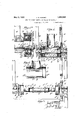
- the invention comprises the combination of members and arrangement of parts so combined as to co-act and cooperate with each other in the performance of the functions and the accomplishment of the results herein contemplated, and comprises in one of its adaptations the species or preferred form illustrated in the accompanying drawings, in which Fig. l is a vertical section through an assembled hanger hub embodying myinvention;
- Fig. 1 is a sectional view similar to Fig. 1 of one end of a hub casing and showing a slightly modified form of my invention
- Fig. 2 is a section, similar to Fig. 1, show ing the hub casing separated from the other P
- Fig. 3 is a disassembled view, partly in section and partly in elevation,of the spindle and associated parts of the hanger;
- Fig. 4 is a section on the line M of Fig. 1;
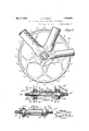
- Fig. 5 is a vertical section through a driving-wheel hub showing a modified form of my invention
- V 7 Fig. 6 is a vertical section of a front-wheel hub showing said modified form of my invention applied thereto.
- 1 indicates a hanger hub comprising a hub-casing 2 suitably supported or hung from frame bars 3 and provided at opposite sides or ends with seats 4, 4 for ballbearing units 5 comprising an outer ball-race member 5, an'
- Said seats 4 are of a diameter increased over the central portion 4 to form radial shoulders 4 and are adapted to frictionally engage the outer periphery and one radial side edge of the outer ball-race member 5 of said ballbearing unit 5.
- a spindle 6, having a' middle portion 6 i of given diameter is provided at opposite sides of said middle portion with integral collars 6*" of increased diameter but of such size as to be spaced from the inner surface of the casing so as to permit lubricating material to reach the balls 5 through the annular space 6 from lubricating apertures hereinafter described and located at the ner side of the seats 4;, and at the outer sides of these collars I form seats 7 for the reception of the inner race-members 5 of said ballbearing units 5.
- the seats 7 are reduced in diameter to form radial shoulders 7 adapted to be arranged in vertical alignment with the radial shoulders 4 in the hub case.
- the spindle 6 is provided at the side of said seat 7 opposite to the radial shoulders 7 with reduced screw-threaded sections 7 adapted to receive nut-washers 8 having internal screwthreaded bores 8' and provided with annular centrally-located hub-portions 8 adapted to engage the outer radial edges of the inner race members 5 and to securely clamp the same against the shoulders 7'.
- the opposite ends of the spindle are still further reduced in diameter to provide seats 9 for the crank member 10 at one side and for the combined crank and sprocket 11 at the other side, and these seats are provided with locking notches 9 adapted to engage locking pins 12 which are passed through pin holes 13 in the hubs of members 10 and 11 to securely fasten these members 10 and 11 to opposite ends of the spindle.
- the radial washer-flange 8 of the nut-washer 8 at one side of the hub is of a diameter sufi'icient to substantially register with the outer surface of the hub casing to close the outer radial face of the ballbearing unit while the radial flange 8 at the other side is somewhat reduced to fit within a hol-' low or depression 11' in the hub of said member 11 and the inner face of this hub portion,
- the member 11 has a sprocket-wheel 14 mounted on the same and fastened thereto by bolts 14.
- holes 15 positioned above the spindle adj acent to the ballbearing units.
- the nut washers are also preferably provided. with holes 16 in alignment with the balls of the units so that lubricating oil may be fed directly into the outer series of balls. These holes also serve the function of wrench holes for. fastening thev washers on the spindles.
- a hub casing 20 has formed at opposite ends seats 21, for ballbearing units22, formed in hub members 21 of a diameter increased in relation to the middle portion 20 of the casing.
- the ballbearing units 22 comprise an outer ball racemember 23, aninner ball race-member 24 and having a seriesof; balls 25 arranged between the race members and heldin place by a retainer 26,
- the seats 21 have an annular surface 2 1, and a radial shoulder 21 which are adapted, to frictionally engage the outer periphery and one radial sideedge of the outer ball race-member 23 of said ballbearing unit22.
- a spindle26 having a middle portion 26 of given diameter is provided at opposite sides ofsaid middle portion with integral colla rs26 of increaseddiameter and at the outer sidesof these collars 1; form seats 27 for, the reception of the innerrace-member 24 of said ballbearing, units 22.
- These seats are providedwith radial shoulders 27 'adapted to be positioned in vertical alignment with the radial shoulders 21 of the seat in the hub
- the spindle 26 is provided at theside of the seat 27; opposite to the radial shoulder 27 with screw-threaded.sections27 of reduced preventing theentra-nce. to the bearing ofv dust, dirt and the like;
- the middle portion 21! of :the hub casing 20 is provided with a lubricating aperture 30 which preferably has communicating therewith a lubricating cup 31 thus enabling lubrication to be passed into the casing without the entry of dust and dirt.
- a hub for a driving wheel has the hub casing member at one. side provided with screwthreaded surfaces 32, 32' for the purpose of mounting therein in the conventional manner a sprocket and washer not shown.
- Fig. 6 I have shown a hub casing for the front wheel ofa bicycle which is substantially similar tothe embodiment shown in Fig. 5 except that the collars 26 have reduced radial ollar-portions 3 f rmed athe ppo teside hereof to gage un n iaceembe o i 3 1 7- bearing units substantially similar to those shownin Fig.5.,
- Igclaim 1 A hub for crank hangers. and wheels of bicycles. embodying, incombination, a cylindrical hub casing open; at Qppositeiends, ballbearing units separable. from -.said-;casing-. and: composed of innertand outenrace-members, ball members interposed between said race-members retainers for spacing apart:
- saidibalLmembers said hubhaving atopposite, ends seatslfor, frictionally; engagingthe outer. race-members of; said 1 ballbearing, units, aspindle having at opposite, ends seatsl for the, inner race-members of said ;ballbe.ar-. ing units, an-annular radially+disposed2mem+ ber closing the. outer-. face ofa'saidrhub .to pret vent: the access of dust. and, dirt :to the .ball;
- a hub for crank hangers and Wheels of bicycles embodying, in combination, a cylindrical hub casing open at opposite ends, ballbearing units separable from said casing and composed of inner and outer racemembers, ball members interposed between said race-members, retainers for spacing apart said ball members, said hub having at opposite ends seats for frictionally engaging the outer race-members of said ballbearing units, a spindle having at opposite ends seats for the inner race-members of said ballbearing units, an annular radially-disposed member closing the outer face of said hub to prevent the access of dust and dirt to the ball members of said ballbearing units, the seats J for the ballbearing race members in the casing and spindle being arranged to provide an annular space at the inner side of ballbearing units to permit access of lubricating from the inner side, and said hub casing being provided between its closed opposite ends with means for applying lubrication to the said ballbearin'g units.
Landscapes
- Engineering & Computer Science (AREA)
- Mechanical Engineering (AREA)
- Chemical & Material Sciences (AREA)
- Combustion & Propulsion (AREA)
- Transportation (AREA)
- Transmission Devices (AREA)
Description
May 3, 1932. KOPSKY 1,856,959 I HUB FOR CRANK HANGERS AND WHEELS OF BICYCLES Filed April 11, 1931 2 SheetsSheet 1 y 3,- 1932- J. G. KOPSKY' 1,856,959
HUB FOR CRANK HANGERS AND WHEELS OF BICYCLES Filed April 11, 1931 2 Sheets-Sheet 2 I I HWIW ATTORNEY Patented May 3, 1932 UNITED STATES PATENT .OFFICE HUB FOR CRANK HANGERS AND WHEELS OF BICYCLES Application filed April 11,
This invention relates to improvements in hubs for crank hangers and wheels of b1- cycles.
The primary object of this invention is to ,6 produce a novel hub for bicycle crank-hangers and bicycle wheels in which ballbearing units may be mounted to enable increased efiiciency in the ballbearing co-action between the hub-casingsand spindles, which will en- 1 able a double bearing to be produced in which the ballbearings will be completely inclosed and kept free from dust and dirt while at the same time providing for lubrication of the ball members in the ballbearing units.
With these and other objects in view, the invention comprises the combination of members and arrangement of parts so combined as to co-act and cooperate with each other in the performance of the functions and the accomplishment of the results herein contemplated, and comprises in one of its adaptations the species or preferred form illustrated in the accompanying drawings, in which Fig. l is a vertical section through an assembled hanger hub embodying myinvention;
Fig. 1 is a sectional view similar to Fig. 1 of one end of a hub casing and showing a slightly modified form of my invention;
Fig. 2 is a section, similar to Fig. 1, show ing the hub casing separated from the other P Fig. 3 is a disassembled view, partly in section and partly in elevation,of the spindle and associated parts of the hanger;
Fig. 4 is a section on the line M of Fig. 1;
Fig. 5 is a vertical section through a driving-wheel hub showing a modified form of my invention; and V 7 Fig. 6 is a vertical section of a front-wheel hub showing said modified form of my invention applied thereto.
Referring now to these drawings, 1 indicates a hanger hub comprising a hub-casing 2 suitably supported or hung from frame bars 3 and provided at opposite sides or ends with seats 4, 4 for ballbearing units 5 comprising an outer ball-race member 5, an'
inner ball-race member 5 having two series of balls 5 arranged between the race mem- 1931. Serial No. 529,421.
bers and held in place by spacing retainers 5 Said seats 4 are of a diameter increased over the central portion 4 to form radial shoulders 4 and are adapted to frictionally engage the outer periphery and one radial side edge of the outer ball-race member 5 of said ballbearing unit 5.
A spindle 6, having a' middle portion 6 i of given diameter is provided at opposite sides of said middle portion with integral collars 6*" of increased diameter but of such size as to be spaced from the inner surface of the casing so as to permit lubricating material to reach the balls 5 through the annular space 6 from lubricating apertures hereinafter described and located at the ner side of the seats 4;, and at the outer sides of these collars I form seats 7 for the reception of the inner race-members 5 of said ballbearing units 5. The seats 7 are reduced in diameter to form radial shoulders 7 adapted to be arranged in vertical alignment with the radial shoulders 4 in the hub case. The spindle 6 is provided at the side of said seat 7 opposite to the radial shoulders 7 with reduced screw-threaded sections 7 adapted to receive nut-washers 8 having internal screwthreaded bores 8' and provided with annular centrally-located hub-portions 8 adapted to engage the outer radial edges of the inner race members 5 and to securely clamp the same against the shoulders 7'. The opposite ends of the spindle are still further reduced in diameter to provide seats 9 for the crank member 10 at one side and for the combined crank and sprocket 11 at the other side, and these seats are provided with locking notches 9 adapted to engage locking pins 12 which are passed through pin holes 13 in the hubs of members 10 and 11 to securely fasten these members 10 and 11 to opposite ends of the spindle. The radial washer-flange 8 of the nut-washer 8 at one side of the hub is of a diameter sufi'icient to substantially register with the outer surface of the hub casing to close the outer radial face of the ballbearing unit while the radial flange 8 at the other side is somewhat reduced to fit within a hol-' low or depression 11' in the hub of said member 11 and the inner face of this hub portion,
in conjunction with the washer portion 8" close the radial face of the unit at that side. As illustrated, the member 11 has a sprocket-wheel 14 mounted on the same and fastened thereto by bolts 14.
Means for lubricating the ballbearing units is provided and in the embodiment shown, I
employ lubricating cups 15 mounted above.
In, Fig. 5 I have shown a modified construction ofhub for the rear driving wheel. In this embodiment a hub casing 20 has formed at opposite ends seats 21, for ballbearing units22, formed in hub members 21 of a diameter increased in relation to the middle portion 20 of the casing. The ballbearing units 22 comprise an outer ball racemember 23, aninner ball race-member 24 and having a seriesof; balls 25 arranged between the race members and heldin place by a retainer 26, The seats 21 have an annular surface 2 1, and a radial shoulder 21 which are adapted, to frictionally engage the outer periphery and one radial sideedge of the outer ball race-member 23 of said ballbearing unit22.
A spindle26 having a middle portion 26 of given diameter is provided at opposite sides ofsaid middle portion with integral colla rs26 of increaseddiameter and at the outer sidesof these collars 1; form seats 27 for, the reception of the innerrace-member 24 of said ballbearing, units 22. These seats are providedwith radial shoulders 27 'adapted to be positioned in vertical alignment with the radial shoulders 21 of the seat in the hub The spindle 26is provided at theside of the seat 27; opposite to the radial shoulder 27 with screw-threaded.sections27 of reduced preventing theentra-nce. to the bearing ofv dust, dirt and the like;
The middle portion 21! of :the hub casing 20 is provided with a lubricating aperture 30 which preferably has communicating therewith a lubricating cup 31 thus enabling lubrication to be passed into the casing without the entry of dust and dirt.
The hub shown in Fig. 5, being, as aforesaid, a hub for a driving wheel has the hub casing member at one. side provided with screwthreaded surfaces 32, 32' for the purpose of mounting therein in the conventional manner a sprocket and washer not shown. In Fig. 6 I have shown a hub casing for the front wheel ofa bicycle which is substantially similar tothe embodiment shown in Fig. 5 except that the collars 26 have reduced radial ollar-portions 3 f rmed athe ppo teside hereof to gage un n iaceembe o i 3 1 7- bearing units substantially similar to those shownin Fig.5.,
In. E g- I; h ve own a m difie oam; of. usthie di g m n dapte a euse in connectiomwith theoonstruction showndn g- S id gure she -s.- a c n ruction which wi be. in all; r spec sls mii arto that shownv in Fig. 1 except; that the.- threaded c ion v a df ut as ers a e imina anda, dust flange. 34 fastened? by-screws 35,; tothe outer radial ed-ges pf the h-ub,casing- -2 and a bushing 35-, are. subSt-ituted; therefor e dustflai'ige hasan n ular bore o ly fitting the bushing, 36 onihesp ndle p tion- 79 so s. t exclude u t and: dirt; om he bearing.- The ballbearing. unit; is;' further. cla pedto. h pindle ndf oqk d iplace by. the hubsof the zcrankr ds-LO and ll abuttingagainst the bushing 35whifch hubs arelprefer ably] fastened; to the. spindle: in the mannershowninFig. 1;
It will; be; seen from the above that; I, have provided-hubs for bicycle crank hangers-and,
wheels in which ballbearing units, separable from the lasing.' or K housingr and; shaft, may be mounted to. .provide inc e s dwfiiciency/in. the ballbearinglco action between therhub cas ings-and Spindle andzwbich wilhenable the ballbearing, units; to be complete y. enclosed and kept free from dust and dirt while authe same time providing fon lubrication. of; the ball members of such.ballbearingmnits,
Having described {my invention, Igclaim 1. A hub for crank hangers. and wheels of bicycles. embodying, incombination, a cylindrical hub casing open; at Qppositeiends, ballbearing units separable. from -.said-;casing-. and: composed of innertand outenrace-members, ball members interposed between said race-members retainers for spacing apart:
saidibalLmembers, said hubhaving atopposite, ends seatslfor, frictionally; engagingthe outer. race-members of; said 1 ballbearing, units, aspindle having at opposite, ends seatsl for the, inner race-members of said ;ballbe.ar-. ing units, an-annular radially+disposed2mem+ ber closing the. outer-. face ofa'saidrhub .to pret vent: the access of dust. and, dirt :to the .ball;
members of said ballbearing units, and means at the outer end of the said spindle for looking the ballbearing units thereto.
2. A hub for crank hangers and Wheels of bicycles embodying, in combination, a cylindrical hub casing open at opposite ends, ballbearing units separable from said casing and composed of inner and outer racemembers, ball members interposed between said race-members, retainers for spacing apart said ball members, said hub having at opposite ends seats for frictionally engaging the outer race-members of said ballbearing units, a spindle having at opposite ends seats for the inner race-members of said ballbearing units, an annular radially-disposed member closing the outer face of said hub to prevent the access of dust and dirt to the ball members of said ballbearing units, the seats J for the ballbearing race members in the casing and spindle being arranged to provide an annular space at the inner side of ballbearing units to permit access of lubricating from the inner side, and said hub casing being provided between its closed opposite ends with means for applying lubrication to the said ballbearin'g units.
In Witness whereof, I have signed my name to the foregoing specification.
JOSEPH G. KOPSKY.
Priority Applications (1)
| Application Number | Priority Date | Filing Date | Title |
|---|---|---|---|
| US529421A US1856959A (en) | 1931-04-11 | 1931-04-11 | Hub for crank hangers and wheels of bicycles |
Applications Claiming Priority (1)
| Application Number | Priority Date | Filing Date | Title |
|---|---|---|---|
| US529421A US1856959A (en) | 1931-04-11 | 1931-04-11 | Hub for crank hangers and wheels of bicycles |
Publications (1)
| Publication Number | Publication Date |
|---|---|
| US1856959A true US1856959A (en) | 1932-05-03 |
Family
ID=24109843
Family Applications (1)
| Application Number | Title | Priority Date | Filing Date |
|---|---|---|---|
| US529421A Expired - Lifetime US1856959A (en) | 1931-04-11 | 1931-04-11 | Hub for crank hangers and wheels of bicycles |
Country Status (1)
| Country | Link |
|---|---|
| US (1) | US1856959A (en) |
Cited By (1)
| Publication number | Priority date | Publication date | Assignee | Title |
|---|---|---|---|---|
| US4883368A (en) * | 1987-12-08 | 1989-11-28 | Stein James A | Grease injector for bicycle crank bearings |
-
1931
- 1931-04-11 US US529421A patent/US1856959A/en not_active Expired - Lifetime
Cited By (1)
| Publication number | Priority date | Publication date | Assignee | Title |
|---|---|---|---|---|
| US4883368A (en) * | 1987-12-08 | 1989-11-28 | Stein James A | Grease injector for bicycle crank bearings |
Similar Documents
| Publication | Publication Date | Title |
|---|---|---|
| DE3539597A1 (en) | BICYCLE POWER GENERATOR | |
| US1433014A (en) | Compound ball bearing | |
| US1856959A (en) | Hub for crank hangers and wheels of bicycles | |
| US6095691A (en) | Crank axle for bicycle | |
| US4632415A (en) | Fork ends and hub of bicycle | |
| US1105268A (en) | Ball-bearing. | |
| US2194817A (en) | Ball bearing construction | |
| US3030825A (en) | Differential | |
| US1908743A (en) | Resilient mounting for bearings | |
| US3551004A (en) | Bicycle improvement | |
| US1401349A (en) | Louis miquet | |
| US1373707A (en) | Velocipede | |
| US611137A (en) | Bicycle crank-shaft bearing | |
| US612401A (en) | Ball-bearing mechanism | |
| US701028A (en) | Bicycle-pedal. | |
| US1782973A (en) | Ball-bearing pedal for bicycles, etc. | |
| US1330579A (en) | Roller-bearing | |
| US1448312A (en) | Hub | |
| US1848427A (en) | Hinge | |
| US1455479A (en) | Pulley and similar construction | |
| US549313A (en) | Bicycle-bearing | |
| US698941A (en) | Bicycle-wheel hub. | |
| US1709739A (en) | Motor tractor | |
| US596984A (en) | Ball-bearing | |
| US608961A (en) | William r |