US1856952A - Process for working guide sleeves for spring rings - Google Patents
Process for working guide sleeves for spring rings Download PDFInfo
- Publication number
- US1856952A US1856952A US509966A US50996631A US1856952A US 1856952 A US1856952 A US 1856952A US 509966 A US509966 A US 509966A US 50996631 A US50996631 A US 50996631A US 1856952 A US1856952 A US 1856952A
- Authority
- US
- United States
- Prior art keywords
- catch
- slot
- spring
- guide sleeves
- working
- Prior art date
- Legal status (The legal status is an assumption and is not a legal conclusion. Google has not performed a legal analysis and makes no representation as to the accuracy of the status listed.)
- Expired - Lifetime
Links
- 238000000034 method Methods 0.000 title description 9
- 238000005520 cutting process Methods 0.000 description 6
- 238000003801 milling Methods 0.000 description 5
- 238000003780 insertion Methods 0.000 description 3
- 230000037431 insertion Effects 0.000 description 3
- 238000000151 deposition Methods 0.000 description 1
- 238000004519 manufacturing process Methods 0.000 description 1
- 238000003825 pressing Methods 0.000 description 1
- 238000007493 shaping process Methods 0.000 description 1
- 238000005476 soldering Methods 0.000 description 1
- 239000000725 suspension Substances 0.000 description 1
Images

Classifications
-
- B—PERFORMING OPERATIONS; TRANSPORTING
- B21—MECHANICAL METAL-WORKING WITHOUT ESSENTIALLY REMOVING MATERIAL; PUNCHING METAL
- B21D—WORKING OR PROCESSING OF SHEET METAL OR METAL TUBES, RODS OR PROFILES WITHOUT ESSENTIALLY REMOVING MATERIAL; PUNCHING METAL
- B21D53/00—Making other particular articles
- B21D53/44—Making other particular articles fancy goods, e.g. jewellery products
-
- F—MECHANICAL ENGINEERING; LIGHTING; HEATING; WEAPONS; BLASTING
- F16—ENGINEERING ELEMENTS AND UNITS; GENERAL MEASURES FOR PRODUCING AND MAINTAINING EFFECTIVE FUNCTIONING OF MACHINES OR INSTALLATIONS; THERMAL INSULATION IN GENERAL
- F16B—DEVICES FOR FASTENING OR SECURING CONSTRUCTIONAL ELEMENTS OR MACHINE PARTS TOGETHER, e.g. NAILS, BOLTS, CIRCLIPS, CLAMPS, CLIPS OR WEDGES; JOINTS OR JOINTING
- F16B45/00—Hooks; Eyes
- F16B45/04—Hooks with sliding closing member
- F16B45/053—Hooks with sliding closing member provided with a cavity in a shank of the hook forming a track or way for the closing member
-
- F—MECHANICAL ENGINEERING; LIGHTING; HEATING; WEAPONS; BLASTING
- F16—ENGINEERING ELEMENTS AND UNITS; GENERAL MEASURES FOR PRODUCING AND MAINTAINING EFFECTIVE FUNCTIONING OF MACHINES OR INSTALLATIONS; THERMAL INSULATION IN GENERAL
- F16B—DEVICES FOR FASTENING OR SECURING CONSTRUCTIONAL ELEMENTS OR MACHINE PARTS TOGETHER, e.g. NAILS, BOLTS, CIRCLIPS, CLAMPS, CLIPS OR WEDGES; JOINTS OR JOINTING
- F16B45/00—Hooks; Eyes
- F16B45/04—Hooks with sliding closing member
- F16B45/057—Hooks with sliding closing member the hook forming a loop or ring when interlocked with the closing member, i.e. the entire structure of the hook being loop shaped
-
- Y—GENERAL TAGGING OF NEW TECHNOLOGICAL DEVELOPMENTS; GENERAL TAGGING OF CROSS-SECTIONAL TECHNOLOGIES SPANNING OVER SEVERAL SECTIONS OF THE IPC; TECHNICAL SUBJECTS COVERED BY FORMER USPC CROSS-REFERENCE ART COLLECTIONS [XRACs] AND DIGESTS
- Y10—TECHNICAL SUBJECTS COVERED BY FORMER USPC
- Y10T—TECHNICAL SUBJECTS COVERED BY FORMER US CLASSIFICATION
- Y10T29/00—Metal working
- Y10T29/49—Method of mechanical manufacture
- Y10T29/49588—Jewelry or locket making
- Y10T29/49595—Latch, clasp, or fastener component making
Definitions
- This invention relates to a process for working guide sleeves for spring rings.
- spring rings are used as fastening means for ornamental chains of all kinds and also as connecting means for Watch-key and similar chains. They consistessentially of three parts, namely the sleeve, bent ringshape, the catch guided in this sleeve, and the catch spring pressing the catch continually into its locking position.
- Spring rings are known with slotted or unslotted guide sleeves.
- the longitudinal slot provided in the slotted guide sleeves serves for guiding the shank of the catch button projecting through the slot on which the catch made of wire can be displaced against the action of the catch spring so that the ring gap in the sleeve bridged by the spring actuated catch opens.
- This invention solves this problem in a very satisfactory manner, both from a technical as also from an economical point of view.
- the new process consists in that the longitudinal slot of the guide sleeve is cut by a milling cutter, saw or the like and then finished by means of a like or similar tool the cutting edge of which is however moved in the opposite direction, that moreover the cutting surface visible from the outer side, produced by the cutting of the slot, and the burr-like edge existing on the edge of this latter are removed by means of tapered end mills, and at the same time a funnel-shaped insertion opening is produced for the catch spring and the catch.
- Fig. 1 is a front elevation of a periodically rotated revolving disc onto which the sleeves are deposited for working.
- Fig. 2 is a top plan view of the revolving disc and of the working toolsarranged on its circumference. '55
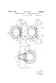
- Figs. 3, fl; and'5 are each a top plan view of the first, second, third and fifth working point.
- Fig. 6 is a top plan View partly in section of a spring sleeve ready for the introduction cc of the catch spring and of the catch pin.
- Fig. 7 shows in front view the slot after the first and secon'doperations.
- Fig. 8 shows in front view the-finished widened slot.
- the guide sleeves'z' To bring the guide sleeves'z' to the first working point, that is in the example shown to the milling cutter p, they are each placed by hand or with the aid of -a special feeding and depositing device in a ring-shaped .de- 7 pression m of a revolving disc n which is intermittently rotated in known manner. Byfmeans of this disc the blanks are fed to the difierent working points.
- the guide sleeves i are deposited in such a manner that in all blanks theslot i is situated-at the proper position, that isv shortly behind the gap in the sleeves.
- a second disc cutter g engages in the slot 2' provided with the burr i
- This cutter rotates in the direction D, which is opposite to the direction B. It has been found that the slot burr '1 which hitherto yielded to the cutter p and remained adhering to the edge of the slot, isbroken u and completely removed.
- the slot i is in itself too narrow for inserting the spring and catch. 7 It is widened at the fourth working point by means of a tapered ram a, Fig. 2, so that it receives the shape shown in Fig. 8.
- the finished worked blank 1' is lifted off the revolving disc n by means of the ejector o.
- the finishing of the spring ring is effected by a separate device or by hand in that, after the soldering on of the suspension eye, the catch spring and the catch are inserted and then the walls of the slot i returned into their parallel position by compressing the guide sleeve 2'.
- I claim 1 A process for working guide sleeves for spring rings, consisting in cutting the slot, in which the shank of the catch button runs, by means of a cutter, and in finishing said slot by means of a similar tool the cutting edge of which moves in opposite direction.
- a process as specified in claim 1, consisting in removing cut faces visible from the outer side formed by the cutting of the slot and the burr-like sharp edges formed on the edges of said faces by means of tapered end mills, and in producing at the same time a funnel-shaped opening for inserting the catch spring and the catch.
Landscapes
- Engineering & Computer Science (AREA)
- General Engineering & Computer Science (AREA)
- Mechanical Engineering (AREA)
- Constituent Portions Of Griding Lathes, Driving, Sensing And Control (AREA)
Description
y 3, 1932- B. FOERSTER I 1,856,952
PROCESS FOR WORKING GUIDE SLEEVES FOR SPRING RINGS Filed Jan. 20, 1931 2 Sheets-Sheet l y 3, 1932- B. FOERSTER 1,856,952
PROCESS FOR WORKING GUIDE SLEEVES FOR SPRING RINGS Filed Jan. 20, 1931 2 Sheets-Sheet 2 Patented May 3, 1932 UNITED STATES BEBNHARD FOERSTER, OF PFORZHEIM, GERMANY PROCESS FOR WORKING GUIDE SLEEVES FOR SPRING-"RINGS Application filed January 20, 1931, Serial No. 509,966, and in Germany October 14, 1929.
This invention relates to a process for working guide sleeves for spring rings.
As is known spring rings are used as fastening means for ornamental chains of all kinds and also as connecting means for Watch-key and similar chains. They consistessentially of three parts, namely the sleeve, bent ringshape, the catch guided in this sleeve, and the catch spring pressing the catch continually into its locking position.
Spring rings are known with slotted or unslotted guide sleeves. The longitudinal slot provided in the slotted guide sleeves serves for guiding the shank of the catch button projecting through the slot on which the catch made of wire can be displaced against the action of the catch spring so that the ring gap in the sleeve bridged by the spring actuated catch opens.
In the mass production of a small object such as the guide sleeve, special diiiiculties are encountered in making a clean usable longitudinal slot. This should aiford agood smooth guiding with suitable stop ends for the shank of the catch to be easily inserted in the guide sleeve. For this purpose it is essential that all kinds of burr are removed without expensive subsequent manual labor and further that the slot is of suitable form for inserting the catch spring and the catch.
This invention solves this problem in a very satisfactory manner, both from a technical as also from an economical point of view.
The new process consists in that the longitudinal slot of the guide sleeve is cut by a milling cutter, saw or the like and then finished by means of a like or similar tool the cutting edge of which is however moved in the opposite direction, that moreover the cutting surface visible from the outer side, produced by the cutting of the slot, and the burr-like edge existing on the edge of this latter are removed by means of tapered end mills, and at the same time a funnel-shaped insertion opening is produced for the catch spring and the catch.
The process is hereinafter described with reference to the accompanying drawings, in which:
Fig. 1 is a front elevation of a periodically rotated revolving disc onto which the sleeves are deposited for working.
Fig. 2 is a top plan view of the revolving disc and of the working toolsarranged on its circumference. '55
Figs. 3, fl; and'5 are each a top plan view of the first, second, third and fifth working point.
Fig. 6 is a top plan View partly in section of a spring sleeve ready for the introduction cc of the catch spring and of the catch pin.
Fig. 7 shows in front view the slot after the first and secon'doperations.
Fig. 8 shows in front view the-finished widened slot.
To bring the guide sleeves'z' to the first working point, that is in the example shown to the milling cutter p, they are each placed by hand or with the aid of -a special feeding and depositing device in a ring-shaped .de- 7 pression m of a revolving disc n which is intermittently rotated in known manner. Byfmeans of this disc the blanks are fed to the difierent working points. The guide sleeves i are deposited in such a manner that in all blanks theslot i is situated-at the proper position, that isv shortly behind the gap in the sleeves. I-n'order to preventthe blank 2' from changing its position in relation to the revolving disc a during the work-' so ing, small retaining pins n fitting exactly in the gaps of the sleeves, are provided in guide the depressions Moreover the blanks i revolving disc at, and exposing, also in a similar manner to the, revolving disc 'n,fso much surface of theblank z as is necessary for the unimpeded working thereof.
In the first working positionshown-on an "enlarged scalefin F ig..3 .theguide slotc' (Fig. 16) forthe shankof thespringlknobis milled.
This is effected by;means o-fadisc cutter p which rotatesfor example'in-the direction B. Experience has shown-that when milling the slot 2' a burr i always remains extending from end to end of the slot. Hitherto the removal of this burr has been laboriously effected by hand.
At the second working point shown on an enlarged scale in Fig. 4 a second disc cutter g engages in the slot 2' provided with the burr i This cutter rotates in the direction D, which is opposite to the direction B. It has been found that the slot burr '1 which hitherto yielded to the cutter p and remained adhering to the edge of the slot, isbroken u and completely removed.
Owing to the milling of the slot 2' with the cutters p and g sloping cut faces 2' visible from the outer side (Figs. 4 and 7 are produced at the ends of the slots, which faces impede the insertion both of the catch spring and also of the catch proper, as their inner edges are of burr-like sharpness. Moreover these sloping faces 2' do not afford a good, close fitting abutment for the shank of the catch knob. These sloping faces are removed at the third and fifth working points, shown combined and on a larger scale in Fig. 5, by means of the tapered milling cutters 1" and s so that the insertion opening for the clip spring and the clip, formed by the slot 2', is atthe same time widened in funnel-shape corresponding to the shape of the tapered end mills. Owing to this shaping of the slot the finished, inserted catch slides easily without hindrance.
The slot i is in itself too narrow for inserting the spring and catch. 7 It is widened at the fourth working point by means of a tapered ram a, Fig. 2, so that it receives the shape shown in Fig. 8.
At the last working point the finished worked blank 1' is lifted off the revolving disc n by means of the ejector o.
The finishing of the spring ring is effected by a separate device or by hand in that, after the soldering on of the suspension eye, the catch spring and the catch are inserted and then the walls of the slot i returned into their parallel position by compressing the guide sleeve 2'.
I claim 1. A process for working guide sleeves for spring rings, consisting in cutting the slot, in which the shank of the catch button runs, by means of a cutter, and in finishing said slot by means of a similar tool the cutting edge of which moves in opposite direction.
2. A process as specified in claim 1, consisting in removing cut faces visible from the outer side formed by the cutting of the slot and the burr-like sharp edges formed on the edges of said faces by means of tapered end mills, and in producing at the same time a funnel-shaped opening for inserting the catch spring and the catch.
In testimony whereof I aflix my signature.
BERNHARD FOERSTER. Y
Applications Claiming Priority (1)
| Application Number | Priority Date | Filing Date | Title |
|---|---|---|---|
| DE1856952X | 1929-10-14 |
Publications (1)
| Publication Number | Publication Date |
|---|---|
| US1856952A true US1856952A (en) | 1932-05-03 |
Family
ID=7746273
Family Applications (1)
| Application Number | Title | Priority Date | Filing Date |
|---|---|---|---|
| US509966A Expired - Lifetime US1856952A (en) | 1929-10-14 | 1931-01-20 | Process for working guide sleeves for spring rings |
Country Status (1)
| Country | Link |
|---|---|
| US (1) | US1856952A (en) |
Cited By (2)
| Publication number | Priority date | Publication date | Assignee | Title |
|---|---|---|---|---|
| US4077099A (en) * | 1976-10-07 | 1978-03-07 | Alfredo Cantini | Machine for the production of helical springs and for their introduction into hollow annular safety catches for necklaces |
| US4258459A (en) * | 1977-10-12 | 1981-03-31 | Gori & Zucchi S.P.A. | Machine for automatically preparing and introducing closure sliders inside annular hollow members for producing annular spring safety catches for necklaces, bracelets and the like |
-
1931
- 1931-01-20 US US509966A patent/US1856952A/en not_active Expired - Lifetime
Cited By (2)
| Publication number | Priority date | Publication date | Assignee | Title |
|---|---|---|---|---|
| US4077099A (en) * | 1976-10-07 | 1978-03-07 | Alfredo Cantini | Machine for the production of helical springs and for their introduction into hollow annular safety catches for necklaces |
| US4258459A (en) * | 1977-10-12 | 1981-03-31 | Gori & Zucchi S.P.A. | Machine for automatically preparing and introducing closure sliders inside annular hollow members for producing annular spring safety catches for necklaces, bracelets and the like |
Similar Documents
| Publication | Publication Date | Title |
|---|---|---|
| US2969030A (en) | Production of writing tips | |
| US3742602A (en) | Cutlery and flatware | |
| US1856952A (en) | Process for working guide sleeves for spring rings | |
| US2146964A (en) | Method of making guide holders | |
| US2245031A (en) | Apparatus for making separable fasteners | |
| US3078566A (en) | Confined extrusion method of making hollow articles | |
| US4541470A (en) | Method of producing sewing machine needles | |
| US2078017A (en) | Method of making separable fasteners | |
| US2084078A (en) | Method of making screws | |
| US3164038A (en) | Method of making scissors | |
| US1110762A (en) | Method of making taper pins. | |
| US2038165A (en) | Forging machine | |
| US3122831A (en) | Method of manufacture of metal articles | |
| US1881981A (en) | Method and apparatus for making prongs for loose-leaf binders | |
| US2683431A (en) | Process of forming pen nibs | |
| US3459090A (en) | Clicking die for cutting sheet materials and method of making said die | |
| US2168311A (en) | Blank for and method of making writing pens | |
| JP5901683B2 (en) | How to decorate jewelry | |
| US2150877A (en) | Button manufacture | |
| US2029944A (en) | Recess forming punch and holder | |
| US1424540A (en) | Method for bifurcating blanks | |
| US1391365A (en) | Method of and apparatus for manufacturing crochet-needles | |
| US1014732A (en) | Machine for making wire nails and pins. | |
| US2202230A (en) | Method of forming separable fasteners | |
| US2048709A (en) | Method of making fastener units |