US1856926A - Machine for developing sensitized paper - Google Patents
Machine for developing sensitized paper Download PDFInfo
- Publication number
- US1856926A US1856926A US366690A US36669029A US1856926A US 1856926 A US1856926 A US 1856926A US 366690 A US366690 A US 366690A US 36669029 A US36669029 A US 36669029A US 1856926 A US1856926 A US 1856926A
- Authority
- US
- United States
- Prior art keywords
- roller
- paper
- trough
- machine
- developing
- Prior art date
- Legal status (The legal status is an assumption and is not a legal conclusion. Google has not performed a legal analysis and makes no representation as to the accuracy of the status listed.)
- Expired - Lifetime
Links
- 230000035611 feeding Effects 0.000 description 15
- 230000005484 gravity Effects 0.000 description 10
- 230000008878 coupling Effects 0.000 description 4
- 238000010168 coupling process Methods 0.000 description 4
- 238000005859 coupling reaction Methods 0.000 description 4
- 238000004140 cleaning Methods 0.000 description 2
- 238000010438 heat treatment Methods 0.000 description 2
- 241001547070 Eriodes Species 0.000 description 1
- 238000010276 construction Methods 0.000 description 1
- 238000010017 direct printing Methods 0.000 description 1
- 239000002184 metal Substances 0.000 description 1
- 238000000034 method Methods 0.000 description 1
- 230000000284 resting effect Effects 0.000 description 1
Images
Classifications
-
- G—PHYSICS
- G03—PHOTOGRAPHY; CINEMATOGRAPHY; ANALOGOUS TECHNIQUES USING WAVES OTHER THAN OPTICAL WAVES; ELECTROGRAPHY; HOLOGRAPHY
- G03D—APPARATUS FOR PROCESSING EXPOSED PHOTOGRAPHIC MATERIALS; ACCESSORIES THEREFOR
- G03D5/00—Liquid processing apparatus in which no immersion is effected; Washing apparatus in which no immersion is effected
- G03D5/06—Applicator pads, rollers or strips
- G03D5/067—Rollers
Definitions
- the -object of this invention is to provide a generally improved and novel automatic machine for developing sensitized pan pers by moistening with a speciahchemlcal -solution and whereby copiesfare made by direct printing from originals.
- an undeveloped print is made from an original and thereafter develd oped by moistening, for instance, by contact with a roller which is partly submerged in the developing solution. It is a further object' of this invention to vprovide a developing machine capable of go being operated automatically and athigh speed, of simple-practical construction and arranged to ,permit easy access for cleaning vand repair purposes.
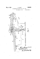
- Figure 1 is a side view of the machine with 3o parts removed and parts broken away.
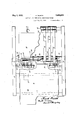
- Figure 2 is a plan view of the machine with parts broken away.
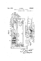
- Figure 3 is a view looking in the direction of arrow 3 in Figure 1.
- Figure 4-i ⁇ s an enlarged detail view show- -ing certain details for feeding the paper through the machine. 1
- a feed board 9 detachably supported on tie rods 7 .by clamps '10 and 11 so arranged that the board is removablev by a lifting and sliding movement.
- the sheet of paper 12 to be developed is laid on the feed board, sensitized face downward and pushed towards and up overthe developing roller 13, Fig. 4, and in between two delivery gripper rollers 14 and 15, where f the sheet is seized by delivery tapes 16 and c 17 which run over the said rollers'14 and '15,', 55 and to and over ⁇ rear tape, rollers 18 and 19.
- the tapes run in contact with eachv other. A and deliver the sheet fiat between them.
- metal delivery board 2O may be placed ben' low the delivering runs of the two tapes and oo a suitable electrical heating element 21 or other heating means may be placed below the delivery board to insurethat the sheet is dry.
- the developing roller 13 runs in a trough 22 filled by any suitable means, not shown, with the developing solution.
- the trough may be lowered and the roller removed for cleaning or other purposes.
- the trough is therefore provided 'with end pins 23,23 car rying spacing collars 24, 24.
- Links 25, 25 have their upper ends pivoted on the pins 23 and their lowest ends connected to arms 26, 26 secured to a trough shaft 27, Figures land 3.
- the trough shaft carries a handle 28 adapted to be held against stop pins 29 or 30 by a spring 31.
- 32, 32 indicate U-shaped' guiding 'loops which pass around the trough shaft 27 and the upper ends of which are fast in the trough 22.
- the ends of the trough pins 23 run in guiding grooves 33 1n the frames 5 and 6.
- the solutionfroller 13 has at one end a 100 shaft 35, Fig. 3 which fits into a coupling 36 on a shaft 37.
- the latter is in driving engagement with a worm wheel 38 driven from a worm 39 in a housing 40.
- the shaft 37 carries a gear 41.
- the coupling 36 is withdrawn from the roller shaft and moved within the gear when it is desired to lower the roller, the gear 41 being then loosened on the shaft37. This is accomplished by operating a knob 42 on the end of the coupling shaft 37. The knob is pulled out to disconnect the coupling from the roller shaft, all in a. well known manner.
- the worm shaft 44 is driven by a motor, not shown.
- the gear 41 drives an idler gear 45 on a stripper shaft 46, Fig. 4.
- the gear 45 drives the intermeshing gears 47 and 48 on the tape rollers 14 and 15 to operate the tapes.
- Means are provided for insuringcontact between the paper and the solution roller.
- the combined weight of the blades 51 which rest by gravity on the paper is sufficient to insure contact with the roller, yet the blades yieldto the edge of the paper and to unevenness therein so as not to prevent the paper from passing over the roller.
- the stripper shaft 46 supports a number of stripper blades 55 which'rest by gravity on the i'oller 13. Each blade is formed with a point'56 and the points of the strippers pievent the .paper from passing around the developing roller.
- the lower tapes 16 are spaced by the collars 60 which position the strippers 55. lVhen the developer roller is lowered the contact blades 51 fall down and come to rest on a rod 75.
- the stripper blades 55 fall anticlockwise against the tape i'oller 14 and rest against the same. When the developer roller is again raised, it automatically engages and lifts the blades 51 and 55 back into normal position.
- this y invention provides a simple automatic high v speed machine inwhich the sensitized paper is developed by contact with the solution roller suflicient for developing purposes.
- tliepaper is barely moistened by the contact with the roller, yet the contactine' eriod is sufficient lone' enough to ac- 1'! D D coniplish the purpose.
- a machine for developing sensitized paper comprising in combination a trough containing the developing solution. a developer roller removably supported in the trough, a plurality of superposed pairs of .driven tapes feeding the paper past the developer roller, gravity operated strippers for preventing the paper from clinging to the developer roller, gravity operated members for insuring contact between the paper and the developing roller and means for driving the latter and the said tapes.
- a machine for developing sensitized paper comprising in combination a pair of frames, a trough containing developing solution adapted to be raised and lowered in said frames from an inoperative vto an operative position, means for operating said trough as v aforesaid, means for guiding the trough in the frames during the movements aforesaid, ya developing roller in said trough, means for feeding the paper past and in ⁇ contact with the said roller and mechanism for operating said feeding means.
- a machine for developing sensitized paper comprising in combination a trough, a developing roller supported therein, means for feeding paper past and in contact with said roller including a plurality of gravity operated members for keeping the paper in contact with the paper, a plurality of strip-- ping elements for stripping the paper fi'oin the said roller, a plurality of tapes for moving the paper past the roller and away therefrom, means for driving the said developing roller and the said tapes and mea-ns for moving said trough and developer roller away from the said tapes for the purposes set forth.
- a machine for developing sensitized paper comprising in combination a vertically connecting and connecting the roller from its driving means when said trough and roller are to be lowered, means for feeding the paper past said roller, gravity operated means for keeping the paper in contact with the roller, gravity operated stripping means for stripping the paper from said roller and a plurality of tapes for moving the paper away from the roller.
- a machine of the character described comprising iii combination a pair of frames, paper feeding means mounted therebetween, a trough'containing the developing solution, a developing roller removablysupported in said trough partially submerged in the solution .therein, means for driving said roller, means for moving said trough and roller into operative relation with said paper feeding means and away therefrom, means for connecting and disconnecting the roller from its driving means to move said roller as aforesaid aiid means actuated by saidv roller for driving the said paper feeding means.
- a machine of the character described comprising in combination a air of frames, paper feeding means mounte therebetween, a trough containingthe developing solution, a developing roller removably supported in said trough partially submerged in the solution therein, means for driving said roller,-
- a machine for developing sensitized paper comprising in combination a trough containing the developing solution, a developer roller in said trough, means for feed ing the paper past said roller, vertically disposed lfreely pivoted blades contacting by gravity 'with the said roller to, insure contact between the paper and the roller, means for supporting the trough and roller in normal operative relation to the said feeding means, mechanism for moving the trough and the roller away from the feeding means and the said blades and a member for supporting the latter when the roller has been moved as aforesaid.
- a machine for developing sensitized paper comprising in combination a trough containing the developing solution, a developer roller in said trough, means for feeding the paper past said roller, vertically disposed freely pivoted blades contacting by gravity with the said roller to insure contact betweenthepaperand the roller, other vertically disposed freel by gravity with thesaid roller to prevent the paper from passing around the same, means for supporting the trough and roller in normal operative relation to the said feed ⁇ ing means, mechanism' for moving the trough and the roller away from the lfeeding' means and the said blades and means for supporting the latter when the roller has been moved as aforesaid.
- a machine for developing sensitized paper comprising in combination a troughV containing the developing solution, a developer roller in said trough, co-operating tape rollers located above the developer'roller and adapted to seize the leading edge of the paper as the latter is fed past the developer rol er, tapes on said tape rollersfor'conveying the developed paper through the machine and a plurality of vertically disposed pivoted blades resting rollerto insure contact between the latter and the paperas it passes into the machine.
Landscapes
- Physics & Mathematics (AREA)
- General Physics & Mathematics (AREA)
- Wet Developing In Electrophotography (AREA)
Description
May 3, 1932. K. MURCK 41,856,926
y MACHINE FOR DEVELOPING SENSITIZED PAPER y Filed May 28, 192s 3 sheets-sheet 1 l, n Summon May 3, 1932.
K. MURCK MACHINE. FOR DEVELOPING SENSITIZED 'PAPER May 31.1932; K. MURCK 1,856,926
MACHINE FOR DEVELOPING SENSITIZED PAPER Fild May 28, 192s :s sheets-sheet s Patented May 3,'. 1 932 UNITED STATES lm'rEN'l OFFICE :anun mmox, or' roansr mns, nnw'voax, Assr'eNon To cnannns :Baume corr-- PANY rnc., a conrona'rron or NEW vom:
MACHINE FOB DEVELOPING SENSITIZED PAPER Application iiled May 28, 1929. Serial No. 366,690.
The -object of this invention is to provide a generally improved and novel automatic machine for developing sensitized pan pers by moistening with a speciahchemlcal -solution and whereby copiesfare made by direct printing from originals.
The art of making copies of drawings and tracings includes certain processes in which prints are made from originals directly on sensitized paper and the latter then developed into positive non-fadingprints byfmoistening with special solutions.
In other words, an undeveloped print is made from an original and thereafter develd oped by moistening, for instance, by contact with a roller which is partly submerged in the developing solution. It is a further object' of this invention to vprovide a developing machine capable of go being operated automatically and athigh speed, of simple-practical construction and arranged to ,permit easy access for cleaning vand repair purposes.
With these and other objects in view, the
invention is embodied in a machine for the purposes set forth arranged and constructed as hereinafter set forth and as illustrated in the accompanying drawings in which Figure 1 is a side view of the machine with 3o parts removed and parts broken away.
Figure 2 is a plan view of the machine with parts broken away.
Figure 3 is a view looking in the direction of arrow 3 in Figure 1. Figure 4-i`s an enlarged detail view show- -ing certain details for feeding the paper through the machine. 1
The several, parts of the machine are generally supported on and between two end frames 5 and 6 which are held together by any suitable means such as tie rods or bolts. Some of these latter are indicated A'at 7 and 8 in Figure 1. v Y
In the front of the machine, at the left in 'Figure 1. there is provided a feed board 9 detachably supported on tie rods 7 .by clamps '10 and 11 so arranged that the board is removablev by a lifting and sliding movement. The sheet of paper 12 to be developed is laid on the feed board, sensitized face downward and pushed towards and up overthe developing roller 13, Fig. 4, and in between two delivery gripper rollers 14 and 15, where f the sheet is seized by delivery tapes 16 and c 17 which run over the said rollers'14 and '15,', 55 and to and over` rear tape, rollers 18 and 19. The tapes run in contact with eachv other. A and deliver the sheet fiat between them. A
metal delivery board 2O may be placed ben' low the delivering runs of the two tapes and oo a suitable electrical heating element 21 or other heating means may be placed below the delivery board to insurethat the sheet is dry.
The developing roller 13 runs in a trough 22 filled by any suitable means, not shown, with the developing solution. The trough may be lowered and the roller removed for cleaning or other purposes. The trough is therefore provided 'with end pins 23,23 car rying spacing collars 24, 24. Links 25, 25 have their upper ends pivoted on the pins 23 and their lowest ends connected to arms 26, 26 secured to a trough shaft 27, Figures land 3.
At one end of the machine outside the frame 5, the trough shaft carries a handle 28 adapted to be held against stop pins 29 or 30 by a spring 31. 32, 32 indicate U-shaped' guiding 'loops which pass around the trough shaft 27 and the upper ends of which are fast in the trough 22. The ends of the trough pins 23run in guiding grooves 33 1n the frames 5 and 6.
In Figures 1 and 3 the trough 22 with the roller 13 is held in its upper operative pos1- tion with the links 25 and arms 26 pn dead center, movement of the arms 26 bemg prevented by the spring 31 as is obvious. When it i's desired to lowerthe trou h, the handle 28 'is swunganti-clockwise in' igure 1 onto the stop pin 29 whereby to rotate the shaft 27 so that the arms 26 and links 25 wllllpull the trough down, the pins 23 and loops 32l guiding the trough so that it moves vertically in an obviousv manner. The sprmg 31 95 swings with the handle 28 and keeps the trough in its lower position. 4A clockwlse movement of thehandle vcauses the trough to be raised to normal position. v
' The solutionfroller 13 has at one end a 100 shaft 35, Fig. 3 which fits into a coupling 36 on a shaft 37. The latter is in driving engagement with a worm wheel 38 driven from a worm 39 in a housing 40. The shaft 37 carries a gear 41. The coupling 36 is withdrawn from the roller shaft and moved within the gear when it is desired to lower the roller, the gear 41 being then loosened on the shaft37. This is accomplished by operating a knob 42 on the end of the coupling shaft 37. The knob is pulled out to disconnect the coupling from the roller shaft, all in a. well known manner. The worm shaft 44 is driven by a motor, not shown.
The gear 41 drives an idler gear 45 on a stripper shaft 46, Fig. 4. The gear 45 drives the intermeshing gears 47 and 48 on the tape rollers 14 and 15 to operate the tapes.
Means are provided for insuringcontact between the paper and the solution roller. On a rod 50, Fig. 4, there is loosely supported a plurality of contact blades 51 spaced apart by collars 52. The combined weight of the blades 51 which rest by gravity on the paper is sufficient to insure contact with the roller, yet the blades yieldto the edge of the paper and to unevenness therein so as not to prevent the paper from passing over the roller.
The stripper shaft 46 supports a number of stripper blades 55 which'rest by gravity on the i'oller 13. Each blade is formed with a point'56 and the points of the strippers pievent the .paper from passing around the developing roller. The frames'support a bar 58 which carries spacing pins 59 for the uppcr tapes 17. The lower tapes 16 are spaced by the collars 60 which position the strippers 55. lVhen the developer roller is lowered the contact blades 51 fall down and come to rest on a rod 75. The stripper blades 55 fall anticlockwise against the tape i'oller 14 and rest against the same. When the developer roller is again raised, it automatically engages and lifts the blades 51 and 55 back into normal position.
From the foregoing it will be clear that this y invention provides a simple automatic high v speed machine inwhich the sensitized paper is developed by contact with the solution roller suflicient for developing purposes. In actual practise tliepaper is barely moistened by the contact with the roller, yet the contactine' eriod is sufficient lone' enough to ac- 1'! D D coniplish the purpose.
I claim:
1. A machine for developing sensitized paper comprising in combination a trough containing the developing solution. a developer roller removably supported in the trough, a plurality of superposed pairs of .driven tapes feeding the paper past the developer roller, gravity operated strippers for preventing the paper from clinging to the developer roller, gravity operated members for insuring contact between the paper and the developing roller and means for driving the latter and the said tapes.
2. A machine for developing sensitized paper comprising in combination a pair of frames, a trough containing developing solution adapted to be raised and lowered in said frames from an inoperative vto an operative position, means for operating said trough as v aforesaid, means for guiding the trough in the frames during the movements aforesaid, ya developing roller in said trough, means for feeding the paper past and in` contact with the said roller and mechanism for operating said feeding means.
3. A machine for developing sensitized paper comprising in combination a trough, a developing roller supported therein, means for feeding paper past and in contact with said roller including a plurality of gravity operated members for keeping the paper in contact with the paper, a plurality of strip-- ping elements for stripping the paper fi'oin the said roller, a plurality of tapes for moving the paper past the roller and away therefrom, means for driving the said developing roller and the said tapes and mea-ns for moving said trough and developer roller away from the said tapes for the purposes set forth.
4. A machine for developing sensitized paper comprising in combination a vertically connecting and connecting the roller from its driving means when said trough and roller are to be lowered, means for feeding the paper past said roller, gravity operated means for keeping the paper in contact with the roller, gravity operated stripping means for stripping the paper from said roller and a plurality of tapes for moving the paper away from the roller.
5. A machine of the character described comprising iii combination a pair of frames, paper feeding means mounted therebetween, a trough'containing the developing solution, a developing roller removablysupported in said trough partially submerged in the solution .therein, means for driving said roller, means for moving said trough and roller into operative relation with said paper feeding means and away therefrom, means for connecting and disconnecting the roller from its driving means to move said roller as aforesaid aiid means actuated by saidv roller for driving the said paper feeding means.
6. A machine of the character described comprising in combination a air of frames, paper feeding means mounte therebetween, a trough containingthe developing solution, a developing roller removably supported in said trough partially submerged in the solution therein, means for driving said roller,-
CII
means and) away therefrom, means for connecting and disconnecting the roller from its driving means to move said roller as aforesaid, yielding means insuring contact between the developing roller and the paper to insure development thereof and means actuated by said roller for driving the said paper feeding means.
7. A machine for developing sensitized paper comprising in combination a trough containing the developing solution, a developer roller in said trough, means for feed ing the paper past said roller, vertically disposed lfreely pivoted blades contacting by gravity 'with the said roller to, insure contact between the paper and the roller, means for supporting the trough and roller in normal operative relation to the said feeding means, mechanism for moving the trough and the roller away from the feeding means and the said blades and a member for supporting the latter when the roller has been moved as aforesaid.
8. A machine for developing sensitized paper comprising in combination a trough containing the developing solution, a developer roller in said trough, means for feeding the paper past said roller, vertically disposed freely pivoted blades contacting by gravity with the said roller to insure contact betweenthepaperand the roller, other vertically disposed freel by gravity with thesaid roller to prevent the paper from passing around the same, means for supporting the trough and roller in normal operative relation to the said feed` ing means, mechanism' for moving the trough and the roller away from the lfeeding' means and the said blades and means for supporting the latter when the roller has been moved as aforesaid.
KNUD MURCK.
ypivotedbladescontacting by gravityon the developer
Priority Applications (1)
| Application Number | Priority Date | Filing Date | Title |
|---|---|---|---|
| US366690A US1856926A (en) | 1929-05-28 | 1929-05-28 | Machine for developing sensitized paper |
Applications Claiming Priority (1)
| Application Number | Priority Date | Filing Date | Title |
|---|---|---|---|
| US366690A US1856926A (en) | 1929-05-28 | 1929-05-28 | Machine for developing sensitized paper |
Publications (1)
| Publication Number | Publication Date |
|---|---|
| US1856926A true US1856926A (en) | 1932-05-03 |
Family
ID=23444079
Family Applications (1)
| Application Number | Title | Priority Date | Filing Date |
|---|---|---|---|
| US366690A Expired - Lifetime US1856926A (en) | 1929-05-28 | 1929-05-28 | Machine for developing sensitized paper |
Country Status (1)
| Country | Link |
|---|---|
| US (1) | US1856926A (en) |
-
1929
- 1929-05-28 US US366690A patent/US1856926A/en not_active Expired - Lifetime
Similar Documents
| Publication | Publication Date | Title |
|---|---|---|
| US2582001A (en) | Photographic print making machine | |
| US3107596A (en) | Photocopy machine | |
| US3164074A (en) | Electrophotographic reproduction machines | |
| US1856926A (en) | Machine for developing sensitized paper | |
| US2928329A (en) | Photographic developing machine | |
| US2287271A (en) | Process camera | |
| US1891722A (en) | Sensitized paper developing apparatus | |
| US3277808A (en) | Apparatus for producing offset printing plates | |
| US1825709A (en) | Coin-operated photographic apparatus | |
| US2158817A (en) | Developing device | |
| US3354807A (en) | Plate processing machine | |
| US2889762A (en) | Photographic developing apparatus | |
| US2282427A (en) | Process camera | |
| US2430687A (en) | Paper feeding mechanism for photocopy machines | |
| US2666384A (en) | Photographic copying apparatus | |
| US2900889A (en) | Photographic printing apparatus | |
| US1421413A (en) | Photographic-printing machine | |
| US3203335A (en) | Developing apparatus for photographic equipment | |
| US3388688A (en) | Electrophotographic apparatus | |
| US1796366A (en) | Photographic-print-treating apparatus | |
| US2014744A (en) | Method and apparatus for developing and treating sheets of sensitized paper | |
| US1894092A (en) | Print treating apparatus | |
| US2747479A (en) | Photographic copying apparatus | |
| US1366748A (en) | Photograph-development apparatus | |
| US1006428A (en) | Photographic printing, developing, and fixing apparatus. |