US1856922A - Phonograph electrical reproducer - Google Patents
Phonograph electrical reproducer Download PDFInfo
- Publication number
- US1856922A US1856922A US273539A US27353928A US1856922A US 1856922 A US1856922 A US 1856922A US 273539 A US273539 A US 273539A US 27353928 A US27353928 A US 27353928A US 1856922 A US1856922 A US 1856922A
- Authority
- US
- United States
- Prior art keywords
- coils
- audio
- phonograph
- reproducer
- coil
- Prior art date
- Legal status (The legal status is an assumption and is not a legal conclusion. Google has not performed a legal analysis and makes no representation as to the accuracy of the status listed.)
- Expired - Lifetime
Links
Images
Classifications
-
- H—ELECTRICITY
- H04—ELECTRIC COMMUNICATION TECHNIQUE
- H04R—LOUDSPEAKERS, MICROPHONES, GRAMOPHONE PICK-UPS OR LIKE ACOUSTIC ELECTROMECHANICAL TRANSDUCERS; ELECTRIC HEARING AIDS; PUBLIC ADDRESS SYSTEMS
- H04R11/00—Transducers of moving-armature or moving-core type
- H04R11/08—Gramophone pick-ups using a stylus; Recorders using a stylus
Definitions
- Reproducers of this character as ordinarily constructed give satisfactory volume and a certain degree of clarity, but are defi- 19 cient in fidelity of reproduction because they.
- the object of the present invention is to provide an electrical reproducing means which will reproduce all frequencies within the audio frequency range at practically equal volume, thus giving greater range and fidelity of reproduction than reproducers of the types heretofore in use.
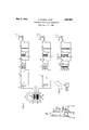
- Figure 1 is a schematic diagram of an electrical reproducer constructed :in accordance with the invention.
- Figure 2 is a similar view disclosing a modification.
- Figure 3 is a similar view disclosing a further modification.
- 1 designates the magnet of an electromagnetic phonographic reproducer, of which 2 is the armature, pivoted at 3 for vibratory or oscillatory motion 4 the phonograph needle carried by the armature, and 5 and 6 electromagnetic pick-up coils. These coils are so placed that the armature 2 when in motion induces electromotive forces therein. These coils are or may be of suitable values to respectively cover the high and low frequency bands in the audio frequency range.
- the coil 5 is connected to a variable resistance 7 a tuning condenser 8 and the primary 9 of the primary transformer 10 of the input circuit 11 of a thermionic amplifier 12, which may be of any suitable number of stages and of any of the types in common use.
- the combination of inductance and capacity in the circuit 11 is adjusted to resonance at a frequency near the lower end of the audio range.
- the resistance 7 is of 1928. Serial No. erases.
- the pick-up coil 6 is connected to the variable resistance 13, tuning coil 14 and primary 15 of the transformer 16, constituting the input circuit 17 of a second thermionic amplifier 18. The combination of inductance and capacity of this circuit l'l is adjusted to resonance ata frequency near the upper end of the audio range.
- the resistance13 broadens this resonance so that the potential generated across the coil 15 by the vibrations of the armature 2 gradually decreases as the frequency of vibration decreases.
- the potential across coil 13 at the lower end of the audio range is infinitely small in comparison with the potential generated by vibrations of armature 2 of equal amplitude at the upper end of the audio range.
- the two amplifier systems are so adjusted that near themid point of the audio frequency range the potentials generated across thetransformer coils 9 and 15 are by vibrations of armature 2 of equal values.
- the amplifier circuits 12 and 18 are respectively connectedat its output ends to reproducers 19 and 20 having single coil ;uni,ts, the' coils of which are or maybe responsive to the frequency ranges of the coils 5 and 6.
- These reproducers or loudspeakers may be of horn, cone or other suitable type, and they may be constructed to reproduce all frequencies of the audio range at nearly equal volume, or each speaker may favor the frequencies handled by the circuit with which it is connected, so that the speaker 19 will be most efficient at the lower frequencies and the speaker 20 most efiicient at the higher frequencies, their conjoint action being, such as to produce great fidelity of reproduction throughout the audio frequency range.
- a single reproducer or loudspeaker 21 having a double coil unit the coils of which are respectively connected to the output ends of the circuits 12 and 18, could be employed in place of the separate speakers 19 and 20 shown in Figure'l.
- an electromagnetic phonographic reproducer having a pluralityof pick-up "coils”, and separate amplifying circuits for the coils, in cooperation with suitable reproducing means, which coils and circuits are designed to operate with greatest efficiency respectively in the high and low frequency bands of the audio frequency range, an accurate response of the reproducing means to all frequencies will be obtained, giving great fidelity as well as clarity and volume of reproduction and thereby overcomprising an electromagnetic pick-up device having a plurality of electromagnetic pick-up coils, reproducing means having a corresponding number of energizing coils, and an audio amplifier connecting each pick-up coil with an energizingcoil and havingits input circuit including said pick-up coil, the primary of an audiotransformer, a condenser for tuning said circuit to resonance at a de termined frequency in the audio frequency range, and a resonance broadening resistance for varying the potentials generated in the primary coil responsive to varying amplitudes of motion of the armature of the pick-up device, the said
Landscapes
- Physics & Mathematics (AREA)
- Electromagnetism (AREA)
- Engineering & Computer Science (AREA)
- Acoustics & Sound (AREA)
- Signal Processing (AREA)
- Audible-Bandwidth Dynamoelectric Transducers Other Than Pickups (AREA)
Description
May 3, 1932. A. MERKEL ET AL PHONOGRAPH ELECTRICAL REPRODUCER Filed April 28, 1928 M i @514 Mwwum [O Patented May 3, 1932 UNITED STATES -1 ATENT OFFlCE 'p ARNO MERKEL, on NEW YQRK, N. Y., AND RICHARD R. HALPENNY, or narnenronr, CONNECTICUT, ASSIGNORS T RAY G. MACPHERSON AND JAMES E. MAGPI-IERSON,
BOTH OF NEW YORK, N. Y.
PHONOGRAPH ELECTRICAL REPRODUCER Application filed April 28,
tion with a thermionic amplifier and a radio reproducer, i. e., loudspeaker.
Reproducers of this character as ordinarily constructed give satisfactory volume and a certain degree of clarity, but are defi- 19 cient in fidelity of reproduction because they.
fail to respond uniformly to all frequencies within the audio frequency range. I
The object of the present invention is to provide an electrical reproducing means which will reproduce all frequencies within the audio frequency range at practically equal volume, thus giving greater range and fidelity of reproduction than reproducers of the types heretofore in use.
In the accompanying drawings,-
Figure 1 is a schematic diagram of an electrical reproducer constructed :in accordance with the invention.
Figure 2 is a similar view disclosing a modification.
Figure 3 is a similar view disclosing a further modification.
Referring now more particularly to the drawings, 1 designates the magnet of an electromagnetic phonographic reproducer, of which 2 is the armature, pivoted at 3 for vibratory or oscillatory motion 4 the phonograph needle carried by the armature, and 5 and 6 electromagnetic pick-up coils. These coils are so placed that the armature 2 when in motion induces electromotive forces therein. These coils are or may be of suitable values to respectively cover the high and low frequency bands in the audio frequency range.
The coil 5 is connected to a variable resistance 7 a tuning condenser 8 and the primary 9 of the primary transformer 10 of the input circuit 11 of a thermionic amplifier 12, which may be of any suitable number of stages and of any of the types in common use. The combination of inductance and capacity in the circuit 11 is adjusted to resonance at a frequency near the lower end of the audio range. The resistance 7 is of 1928. Serial No. erases.
such a value as to broaden this resonant peak so that the potential generated across the transformer primary 9 by the vibrations of the armature ,2 gradually decreases as the frequency of vibration increases- The potential across the .primary 9, at the upper endof the audio range is infinitelys'mall in comparison withthe potential generated by vibration of armature2 of equalamplitude at the lower end of the audio range. The pick-up coil 6 is connected to the variable resistance 13, tuning coil 14 and primary 15 of the transformer 16, constituting the input circuit 17 of a second thermionic amplifier 18. The combination of inductance and capacity of this circuit l'l is adjusted to resonance ata frequency near the upper end of the audio range. The resistance13 broadens this resonance so that the potential generated across the coil 15 by the vibrations of the armature 2 gradually decreases as the frequency of vibration decreases. The potential across coil 13 at the lower end of the audio range is infinitely small in comparison with the potential generated by vibrations of armature 2 of equal amplitude at the upper end of the audio range. The two amplifier systemsare so adjusted that near themid point of the audio frequency range the potentials generated across thetransformer coils 9 and 15 are by vibrations of armature 2 of equal values.
In the organization shownin Figure 1 the amplifier circuits 12 and 18 are respectively connectedat its output ends to reproducers 19 and 20 having single coil ;uni,ts, the' coils of which are or maybe responsive to the frequency ranges of the coils 5 and 6. These reproducers or loudspeakers may be of horn, cone or other suitable type, and they may be constructed to reproduce all frequencies of the audio range at nearly equal volume, or each speaker may favor the frequencies handled by the circuit with which it is connected, so that the speaker 19 will be most efficient at the lower frequencies and the speaker 20 most efiicient at the higher frequencies, their conjoint action being, such as to produce great fidelity of reproduction throughout the audio frequency range.
As shown in Figure 2, a single reproducer or loudspeaker 21 having a double coil unit, the coils of which are respectively connected to the output ends of the circuits 12 and 18, could be employed in place of the separate speakers 19 and 20 shown in Figure'l.
It will be seen that by providing an electromagnetic phonographic reproducer having a pluralityof pick-up "coils", and separate amplifying circuits for the coils, in cooperation with suitable reproducing means, which coils and circuits are designed to operate with greatest efficiency respectively in the high and low frequency bands of the audio frequency range, an accurate response of the reproducing means to all frequencies will be obtained, giving great fidelity as well as clarity and volume of reproduction and thereby overcomprising an electromagnetic pick-up device having a plurality of electromagnetic pick-up coils, reproducing means having a corresponding number of energizing coils, and an audio amplifier connecting each pick-up coil with an energizingcoil and havingits input circuit including said pick-up coil, the primary of an audiotransformer, a condenser for tuning said circuit to resonance at a de termined frequency in the audio frequency range, and a resonance broadening resistance for varying the potentials generated in the primary coil responsive to varying amplitudes of motion of the armature of the pick-up device, the said input circuits of the audio amplifiers being tuned to resonance at different frequencies in the audio range.
Signed at New York, in the county of New York and Stateof New York, this 26th day of April, A. D. 1928.
ARNO MERKEL.
RICHARD R. HALPENNY.
Priority Applications (1)
| Application Number | Priority Date | Filing Date | Title |
|---|---|---|---|
| US273539A US1856922A (en) | 1928-04-28 | 1928-04-28 | Phonograph electrical reproducer |
Applications Claiming Priority (1)
| Application Number | Priority Date | Filing Date | Title |
|---|---|---|---|
| US273539A US1856922A (en) | 1928-04-28 | 1928-04-28 | Phonograph electrical reproducer |
Publications (1)
| Publication Number | Publication Date |
|---|---|
| US1856922A true US1856922A (en) | 1932-05-03 |
Family
ID=23044354
Family Applications (1)
| Application Number | Title | Priority Date | Filing Date |
|---|---|---|---|
| US273539A Expired - Lifetime US1856922A (en) | 1928-04-28 | 1928-04-28 | Phonograph electrical reproducer |
Country Status (1)
| Country | Link |
|---|---|
| US (1) | US1856922A (en) |
-
1928
- 1928-04-28 US US273539A patent/US1856922A/en not_active Expired - Lifetime
Similar Documents
| Publication | Publication Date | Title |
|---|---|---|
| US2122587A (en) | Acoustic device | |
| US1907723A (en) | Sound reproducing device | |
| US2549963A (en) | Electroacoustic transducer | |
| US2860183A (en) | Sound reproducing system | |
| US4074070A (en) | Supersonic signal linearizes loudspeaker operation | |
| US2593031A (en) | Loud-speaker | |
| US2256270A (en) | Loud-speaker | |
| US2568797A (en) | Microphonic suppression system for electric phonographs | |
| US2037255A (en) | Electromagnetic translating device | |
| US3038964A (en) | Loudspeaker system | |
| US1856922A (en) | Phonograph electrical reproducer | |
| US2535757A (en) | Peripherally driven electroacoustical transducer | |
| US3236958A (en) | Loudspeaker system | |
| US2205365A (en) | Radio receiver | |
| US3015366A (en) | Speaker system | |
| US2489862A (en) | Damping for dynamic loudspeakers | |
| US2123442A (en) | Loud speaker | |
| US1689564A (en) | Means for the radio-translation of phonographically-recorded sound waves | |
| US2141277A (en) | Interference eliminator | |
| US2006847A (en) | Electrodynamic magnet system for microphones, loudspeakers, or similar devices | |
| US2672525A (en) | Sound translating device with resonating and damping chamber | |
| US1868607A (en) | Electromagnetic sound reproducer system | |
| US1732427A (en) | Electric pick-up device | |
| US2040954A (en) | Automatic tone control | |
| US3146848A (en) | Hi-fidelity speaker |