US1856917A - Sucker rod coupling - Google Patents
Sucker rod coupling Download PDFInfo
- Publication number
- US1856917A US1856917A US487977A US48797730A US1856917A US 1856917 A US1856917 A US 1856917A US 487977 A US487977 A US 487977A US 48797730 A US48797730 A US 48797730A US 1856917 A US1856917 A US 1856917A
- Authority
- US
- United States
- Prior art keywords
- box
- sleeve
- pin
- coupling
- movable section
- Prior art date
- Legal status (The legal status is an assumption and is not a legal conclusion. Google has not performed a legal analysis and makes no representation as to the accuracy of the status listed.)
- Expired - Lifetime
Links
- 230000008878 coupling Effects 0.000 title description 23
- 238000010168 coupling process Methods 0.000 title description 23
- 238000005859 coupling reaction Methods 0.000 title description 23
- 238000010276 construction Methods 0.000 description 3
- 238000004519 manufacturing process Methods 0.000 description 2
- 238000005086 pumping Methods 0.000 description 2
- 239000011435 rock Substances 0.000 description 1
- 239000004576 sand Substances 0.000 description 1
- 239000013049 sediment Substances 0.000 description 1
Images
Classifications
-
- E—FIXED CONSTRUCTIONS
- E21—EARTH OR ROCK DRILLING; MINING
- E21B—EARTH OR ROCK DRILLING; OBTAINING OIL, GAS, WATER, SOLUBLE OR MELTABLE MATERIALS OR A SLURRY OF MINERALS FROM WELLS
- E21B17/00—Drilling rods or pipes; Flexible drill strings; Kellies; Drill collars; Sucker rods; Cables; Casings; Tubings
- E21B17/02—Couplings; joints
- E21B17/04—Couplings; joints between rod or the like and bit or between rod and rod or the like
- E21B17/046—Couplings; joints between rod or the like and bit or between rod and rod or the like with ribs, pins, or jaws, and complementary grooves or the like, e.g. bayonet catches
-
- Y—GENERAL TAGGING OF NEW TECHNOLOGICAL DEVELOPMENTS; GENERAL TAGGING OF CROSS-SECTIONAL TECHNOLOGIES SPANNING OVER SEVERAL SECTIONS OF THE IPC; TECHNICAL SUBJECTS COVERED BY FORMER USPC CROSS-REFERENCE ART COLLECTIONS [XRACs] AND DIGESTS
- Y10—TECHNICAL SUBJECTS COVERED BY FORMER USPC
- Y10T—TECHNICAL SUBJECTS COVERED BY FORMER US CLASSIFICATION
- Y10T279/00—Chucks or sockets
- Y10T279/17—Socket type
- Y10T279/17761—Side detent
- Y10T279/17769—Pivoted or rotary
- Y10T279/17777—Sleeved
-
- Y—GENERAL TAGGING OF NEW TECHNOLOGICAL DEVELOPMENTS; GENERAL TAGGING OF CROSS-SECTIONAL TECHNOLOGIES SPANNING OVER SEVERAL SECTIONS OF THE IPC; TECHNICAL SUBJECTS COVERED BY FORMER USPC CROSS-REFERENCE ART COLLECTIONS [XRACs] AND DIGESTS
- Y10—TECHNICAL SUBJECTS COVERED BY FORMER USPC
- Y10T—TECHNICAL SUBJECTS COVERED BY FORMER US CLASSIFICATION
- Y10T403/00—Joints and connections
- Y10T403/66—Interfitted members with external bridging piece
Definitions
- Our invention relates to a sucker rod coupling and the like.
- An object of our invention is to provide a coupling for sucker rods and the like which E can be operated, that is, connected and disconnected in less time than couplings now in use.
- Another object is to provide a coupling for sucker rods which connects and discon- 1 nects without threads, and without screwing l tongue and groove in box.
- Another object is to provide a coupling for sucker rods that will eliminate trouble of rods parting, and thereby prevent loss of time in pumping wells,thereby increasing daily production of oil.
- Another object is to provide a coupling for sucker rods which can be connected and disconnected in less time than what is now required-thereby reducing labor, saving time and money.
- Another object is to provide a coupling for sucker rods that will be simple and convenient in operation, economical in manufacturing, and which is durable.
- the invention consists in the details of con struction and in the combination and arrangement of the several parts of our improved sucker rod coupling whereby certain important advantages are attained and the device rendered simpler, less expensive and otherwise more convenient and advantageous for use, as will be hereinafter more fully set forth.
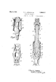
- Fig. 1 represents the coupling with all parts assembled.
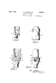
- Fig. 2 represents cross-section of base of box'of coupling and inside face view of stationary section of box of coupling.
- Fig. 3 represents pin of coupling, showing sleeve lifted; which sleeve has a slightly tapered bore to fit around tapered box, when box is closed on pin. 7
- Fig. 4 represents side view of box of coupling, showing'position of movable section of box, and showing a cross-section of stationary section of box in position for the entrance of pin. 7
- Fig. 5 represents an outside view of movable section of box of coupling, showing bolt which attaches movable section to base of stationary section of box, on which movable section swings,s howing how movable section is attached to base of box of coupling.
- Fig. 6 represents inner face View of movable section of box of coupling with bolt in place, also showing tongue and groove in movable section of box.
- Fig. 7 represents a sleeve which fits over or around entire box when closed on pin,- thereby preventing sections of box from opening while rods are in well.
- Fig. 1 When sleeve E is raised, movable section B is released and allowed to open slightly, releasing pin C, which will be free to raise out of box,'this operation takes place when rods are being pulled out ofwell.
- Sleeve E is reduced at top to prevent sliding over pin C when pin C is disconnected from box. This reduction of sleeve however, does not interfere with sleeve passing down over box sufliciently to hold sections of box together. Sleeve fits loosely around shank of pin C. Sleeve E has openings K for the purpose of allowing sand or other sediments which may collect in top of box, to escape.
- Movable section B of box when in operation is pivoted on a bolt H, which works inan oblong hole I; this allowing'free movement inward or outward as may be required to fit closely on pin C.
- Movable section B is held in position by a spring J.
- movable section B of box may be operated with or without spring J.
- the base of box A is made large enough to project beyond the periphery of sleeve, shown at L.
- the purpose of this projection is to prevent sleeve E coming in contact with tubing, to eliminate possibility of sleeve E being moved or loosened by friction.
- This new invented coupling may be made to fit into a string of standard sucker rods of various sizes.
- Box M on bottom of coupling which may be made with threads to fit standard rods of various sizes, is for the purpose of connecting into string of sucker rods.
- Small pin N at top of shank F with threads to fit standard sucker rods of various sizes, is for the purpose of connecting into standard string of sucker rods.
- Non top of shank F is provided with a lock nut O.
- This lock nut O prevents pin N from working loose.
- D represents tongue and groove on pin C and in box A, which tongue and .groove on pin C fits into corresponding tongue and groove in box A, making a rigid connection when sleeve isdropped in position around box.
- P represents flat springs which fastens to shank F by screws Q.
- the purpose of these springs is to hold up sleeve E when raised oil of box, and also to prevent. sleeve E'f-rom jarring upward when well is pumping. Sleeve may be easily raised by slight upward pull of hand, and lowered by slight downward pull of hand.
- Asucker rodcoupling comprising two members, one ofisaid members including .a'gf
- ribbed pin and the other a. grooved box to receive said pin to interlock therewith, said box comprising a fixedsection and a swinging section, said swinging section having a base to be engaged by the end of pin as? the pin entersbetween the sections of the box to tightly engage the pin between. the sections, a sleeve carried by the member having the pin for sliding movement therealong,
- said sleeve being engageable over the sec-9 tions of the second member to hold the pin clamped between said sections, and.yieldable means carried by the second member and coacting with the sleeve to hold the sleeve in applied position with respect to the sections-4' of the box, said means alsoserving to hold the sleeve raised with respect to the pin.
- a sucker rod coupling comprising two members including a pin and'a socket to remeans mounted on said one member and adapted to engage the sleeve upon longitudinal movement thereof whereby to retard the movement of the sleeve on said one member;
- said resilient means resiliently holding said sleeve in locked position about said pin and socket and the oppositeend upon movement of the sleeve into disengaged position holding the sleeve in disengaged po-;
- asucker rod coupling comprising two members, one having a pin and the other a socket to receive the pin, a sleeve longitudinally movable on the first of saidv members, a pivoted locking member carried by the socket and having grooves on the innertace thereof whereby to engage the ribbed portion of the pin, said locking member having anwinwardly extending base portion disposed ceive the pin, a sleeve longitudinally mov-':-:
Landscapes
- Engineering & Computer Science (AREA)
- Life Sciences & Earth Sciences (AREA)
- Geology (AREA)
- Mining & Mineral Resources (AREA)
- Mechanical Engineering (AREA)
- Physics & Mathematics (AREA)
- Environmental & Geological Engineering (AREA)
- Fluid Mechanics (AREA)
- General Life Sciences & Earth Sciences (AREA)
- Geochemistry & Mineralogy (AREA)
- Quick-Acting Or Multi-Walled Pipe Joints (AREA)
Description
y 3, 1932- T. M. JORDAN ET AL 1,356,917
SUCKER ROD COUPLING Filed Oct. 11, 1930 2 Sheets-Sheet 1 7 May 3, 1932.
SUGKER ROD COUPLING Filed Oct. 11, 1930 2 Sheets-Sheet 2 'r. M. JORDAN ET AL ,917 I Patented May 3, 1932 UNITED STATES PATENT FFIcE THOMAS M. JORDAN AND WILLIAM H. HERRINGTON, F KOUNTZE, TEXAS STICKER ROD COUPLING Application filed October 11, 1930. Serial No. 487,977.
Our invention relates to a sucker rod coupling and the like.
An object of our invention is to provide a coupling for sucker rods and the like which E can be operated, that is, connected and disconnected in less time than couplings now in use.
Another object is to provide a coupling for sucker rods which connects and discon- 1 nects without threads, and without screwing l tongue and groove in box.
Another object is to provide a coupling for sucker rods that will eliminate trouble of rods parting, and thereby prevent loss of time in pumping wells,thereby increasing daily production of oil.
Another object is to provide a coupling for sucker rods which can be connected and disconnected in less time than what is now required-thereby reducing labor, saving time and money.
Another object is to provide a coupling for sucker rods that will be simple and convenient in operation, economical in manufacturing, and which is durable.
The invention consists in the details of con struction and in the combination and arrangement of the several parts of our improved sucker rod coupling whereby certain important advantages are attained and the device rendered simpler, less expensive and otherwise more convenient and advantageous for use, as will be hereinafter more fully set forth.
The novel features of our invention will hereinafter be definitely claimed.
In order that our invention may be the better understood, we will now proceed to describe the same with reference to the accompanying drawings, wherein Fig. 1 represents the coupling with all parts assembled.
Fig. 2 represents cross-section of base of box'of coupling and inside face view of stationary section of box of coupling.
Fig. 3 represents pin of coupling, showing sleeve lifted; which sleeve has a slightly tapered bore to fit around tapered box, when box is closed on pin. 7
. Fig. 4 represents side view of box of coupling, showing'position of movable section of box, and showing a cross-section of stationary section of box in position for the entrance of pin. 7
Fig. 5 represents an outside view of movable section of box of coupling, showing bolt which attaches movable section to base of stationary section of box, on which movable section swings,s howing how movable section is attached to base of box of coupling.
Fig. 6 represents inner face View of movable section of box of coupling with bolt in place, also showing tongue and groove in movable section of box.
Fig. 7 represents a sleeve which fits over or around entire box when closed on pin,- thereby preventing sections of box from opening while rods are in well.
Referring to drawings:
Fig. 1: When sleeve E is raised, movable section B is released and allowed to open slightly, releasing pin C, which will be free to raise out of box,'this operation takes place when rods are being pulled out ofwell.
When rods are being put back into well, the following operation: When pin 0 enters box, the movable section B opens and allows pin C to enter box freely, which pin C striking base G of movable section, swings movable section inward, causing it to fit tightly on pin C, then tongue and groove on pin C fits corresponding tongue and groove in box. Sleeve E, which is at this time raised above box, is then allowed to 'drop, and fits closely around entire box, thereby holding sections of box together'forming a complete coupling. This sleeve being slightly tapered to fit tapered box, takes up all slack, moving downward and wedging itself tightly around box.
When the two sections of the box are put together, a slightly tapered cylindrical box is formed, being a little smaller at top than bottom. Sleeve E is made slightly tapered to fit the tapered box.
Sleeve E is reduced at top to prevent sliding over pin C when pin C is disconnected from box. This reduction of sleeve however, does not interfere with sleeve passing down over box sufliciently to hold sections of box together. Sleeve fits loosely around shank of pin C. Sleeve E has openings K for the purpose of allowing sand or other sediments which may collect in top of box, to escape.
Movable section B of box when in operation is pivoted on a bolt H, which works inan oblong hole I; this allowing'free movement inward or outward as may be required to fit closely on pin C. Movable section B is held in position by a spring J. However, movable section B of box may be operated with or without spring J. g
The base of box A is made large enough to project beyond the periphery of sleeve, shown at L. The purpose of this projection is to prevent sleeve E coming in contact with tubing, to eliminate possibility of sleeve E being moved or loosened by friction. f
This new invented coupling may be made to fit into a string of standard sucker rods of various sizes. Box M on bottom of coupling, which may be made with threads to fit standard rods of various sizes, is for the purpose of connecting into string of sucker rods. Small pin N at top of shank F with threads to fit standard sucker rods of various sizes, is for the purpose of connecting into standard string of sucker rods.
This standard connection Non top of shank F is provided with a lock nut O. This lock nut O prevents pin N from working loose.
D represents tongue and groove on pin C and in box A, which tongue and .groove on pin C fits into corresponding tongue and groove in box A, making a rigid connection when sleeve isdropped in position around box.
P represents flat springs which fastens to shank F by screws Q. The purpose of these springs is to hold up sleeve E when raised oil of box, and also to prevent. sleeve E'f-rom jarring upward when well is pumping. Sleeve may be easily raised by slight upward pull of hand, and lowered by slight downward pull of hand.
The above description may be more fully understood'by referring to drawings hereto connected.
It is thought that the construction, operation, utility and advantages of this invention will now be apparent to those skilled in this art without a more detailed description thereof,
The present embodiment of this invention has been described for the purpose of exemplification, and it is to be understood that changes in the details of construction, and in the combination and arrangement of parts,
- may be resorted to without departing from the spirit or scope of the invention as hereinafter damned.-
' member having the pin for sliding movement therealong, said sleeve being engageable over the sections of the second member to hold the pin clamped between said sections, and yield able means carried by the second member and reacting with the sleeve to hold the "sleeve in applied'positionwith respect tothe sections of the box, said means Tupon movement -ofthe sleeve to unapplied position yieldably maintaining the sleeve in such unapplied position.
2. Asucker rodcoupling comprising two members, one ofisaid members including .a'gf
ribbed pin and the other a. grooved box to receive said pin to interlock therewith, said box comprising a fixedsection and a swinging section, said swinging section having a base to be engaged by the end of pin as? the pin entersbetween the sections of the box to tightly engage the pin between. the sections, a sleeve carried by the member having the pin for sliding movement therealong,
said sleeve being engageable over the sec-9 tions of the second member to hold the pin clamped between said sections, and.yieldable means carried by the second member and coacting with the sleeve to hold the sleeve in applied position with respect to the sections-4' of the box, said means alsoserving to hold the sleeve raised with respect to the pin.
3. In a sucker rod coupling comprising two members including a pin and'a socket to remeans mounted on said one member and adapted to engage the sleeve upon longitudinal movement thereof whereby to retard the movement of the sleeve on said one member;
one end ofv said resilient means resiliently holding said sleeve in locked position about said pin and socket and the oppositeend upon movement of the sleeve into disengaged position holding the sleeve in disengaged po-;
sition.
4. In asucker rod coupling comprising two members, one having a pin and the other a socket to receive the pin, a sleeve longitudinally movable on the first of saidv members, a pivoted locking member carried by the socket and having grooves on the innertace thereof whereby to engage the ribbed portion of the pin, said locking member having anwinwardly extending base portion disposed ceive the pin, a sleeve longitudinally mov-':-:
.able 011 one of the members, and resilient in the path of the inner end of the pin whereby to rock the locking member into looking engagement upon contact of the pin with said base portion, and a plurality of resilient members mounted on said first member and adapted to engage the sleeve upon longitudinal movement thereof whereby to retard the movement of the sleeve on said first member, one end of said resilient means resiliently holding said sleeve in locked position about said pin and socket and the opposite end upon movement of the sleeve into disengaged position holding the sleeve in disengaged position.
In testimony whereof we have aflixed our signatures.
THOS. M. JORDAN. WILLIAM H. HERRINGTON.
Priority Applications (1)
| Application Number | Priority Date | Filing Date | Title |
|---|---|---|---|
| US487977A US1856917A (en) | 1930-10-11 | 1930-10-11 | Sucker rod coupling |
Applications Claiming Priority (1)
| Application Number | Priority Date | Filing Date | Title |
|---|---|---|---|
| US487977A US1856917A (en) | 1930-10-11 | 1930-10-11 | Sucker rod coupling |
Publications (1)
| Publication Number | Publication Date |
|---|---|
| US1856917A true US1856917A (en) | 1932-05-03 |
Family
ID=23937881
Family Applications (1)
| Application Number | Title | Priority Date | Filing Date |
|---|---|---|---|
| US487977A Expired - Lifetime US1856917A (en) | 1930-10-11 | 1930-10-11 | Sucker rod coupling |
Country Status (1)
| Country | Link |
|---|---|
| US (1) | US1856917A (en) |
Cited By (8)
| Publication number | Priority date | Publication date | Assignee | Title |
|---|---|---|---|---|
| US2713910A (en) * | 1950-06-19 | 1955-07-26 | Baker Oil Tools Inc | Releasable operating devices for subsurface well tools |
| US4186465A (en) * | 1978-03-28 | 1980-02-05 | Manning Jim L | Safety lock |
| US4710052A (en) * | 1984-03-28 | 1987-12-01 | Gerd Elger | Linear coupling |
| US4717174A (en) * | 1985-10-25 | 1988-01-05 | Kabushiki Kaisha Tokai-Rika-Denki-Seisakusho | Driving force transmitting structure for automatic seatbelt system |
| US5078535A (en) * | 1989-03-02 | 1992-01-07 | Robud Co. | Locking means |
| US20090285625A1 (en) * | 2008-05-16 | 2009-11-19 | Reasoner Michael V | Quick connect with male and female terminals |
| US7740984B2 (en) | 2004-06-04 | 2010-06-22 | Rovcal, Inc. | Alkaline cells having high capacity |
| US9534720B2 (en) | 2014-07-07 | 2017-01-03 | Michael V. Reasoner | Quick connect assembly including for use in pressurized fluid applications and incorporating auto shut-off feature |
-
1930
- 1930-10-11 US US487977A patent/US1856917A/en not_active Expired - Lifetime
Cited By (9)
| Publication number | Priority date | Publication date | Assignee | Title |
|---|---|---|---|---|
| US2713910A (en) * | 1950-06-19 | 1955-07-26 | Baker Oil Tools Inc | Releasable operating devices for subsurface well tools |
| US4186465A (en) * | 1978-03-28 | 1980-02-05 | Manning Jim L | Safety lock |
| US4710052A (en) * | 1984-03-28 | 1987-12-01 | Gerd Elger | Linear coupling |
| US4717174A (en) * | 1985-10-25 | 1988-01-05 | Kabushiki Kaisha Tokai-Rika-Denki-Seisakusho | Driving force transmitting structure for automatic seatbelt system |
| US5078535A (en) * | 1989-03-02 | 1992-01-07 | Robud Co. | Locking means |
| US7740984B2 (en) | 2004-06-04 | 2010-06-22 | Rovcal, Inc. | Alkaline cells having high capacity |
| US20090285625A1 (en) * | 2008-05-16 | 2009-11-19 | Reasoner Michael V | Quick connect with male and female terminals |
| US7927036B2 (en) * | 2008-05-16 | 2011-04-19 | Reasoner Michael V | Quick connect with male and female terminals |
| US9534720B2 (en) | 2014-07-07 | 2017-01-03 | Michael V. Reasoner | Quick connect assembly including for use in pressurized fluid applications and incorporating auto shut-off feature |
Similar Documents
| Publication | Publication Date | Title |
|---|---|---|
| US1856917A (en) | Sucker rod coupling | |
| US2490465A (en) | Earth anchor | |
| US2217072A (en) | Slip supporting device | |
| US2158406A (en) | Liner setter | |
| US3080922A (en) | Multiple zone well production apparatus | |
| US88959A (en) | Ments | |
| US1681699A (en) | Tool joint lock | |
| US1376141A (en) | Lock | |
| US1619784A (en) | Door for cottonseed boxes | |
| US1845707A (en) | Safety tubing hook | |
| US1030084A (en) | Well-tubing safety appliance. | |
| US1418533A (en) | Casing-pulling device | |
| US743543A (en) | Casing-puller. | |
| US559982A (en) | Window-lock | |
| US272671A (en) | Sash-fastener | |
| US1871562A (en) | Pipe clamp | |
| US779789A (en) | Refrigerator-fastening. | |
| US812229A (en) | Sash-lock. | |
| US1484999A (en) | Rod coupling | |
| US1347203A (en) | Combination rod-socket and overshot fishing-tool | |
| US2430343A (en) | Gate lock | |
| US1581270A (en) | Elevator | |
| US972416A (en) | Casing and tubing hook. | |
| US2305709A (en) | Releasable pin tap | |
| US1993739A (en) | Casing elevator |