US185691A - Improvement in governors - Google Patents
Improvement in governors Download PDFInfo
- Publication number
- US185691A US185691A US185691DA US185691A US 185691 A US185691 A US 185691A US 185691D A US185691D A US 185691DA US 185691 A US185691 A US 185691A
- Authority
- US
- United States
- Prior art keywords
- vessel
- tube
- speed
- engine
- valve
- Prior art date
- Legal status (The legal status is an assumption and is not a legal conclusion. Google has not performed a legal analysis and makes no representation as to the accuracy of the status listed.)
- Expired - Lifetime
Links
- 239000007788 liquid Substances 0.000 description 16
- 235000007319 Avena orientalis Nutrition 0.000 description 10
- 241000209763 Avena sativa Species 0.000 description 10
- 235000007558 Avena sp Nutrition 0.000 description 10
- 239000012530 fluid Substances 0.000 description 10
- QSHDDOUJBYECFT-UHFFFAOYSA-N mercury Chemical compound [Hg] QSHDDOUJBYECFT-UHFFFAOYSA-N 0.000 description 8
- 229910052753 mercury Inorganic materials 0.000 description 8
- 230000001105 regulatory Effects 0.000 description 4
- 230000000630 rising Effects 0.000 description 4
- XLYOFNOQVPJJNP-UHFFFAOYSA-N water Substances O XLYOFNOQVPJJNP-UHFFFAOYSA-N 0.000 description 4
- IGTHEWGRXUAFKF-NVJADKKVSA-N 1-cyclopropyl-8-(difluoromethoxy)-7-[(1R)-1-methyl-2,3-dihydro-1H-isoindol-5-yl]-4-oxoquinoline-3-carboxylic acid;methanesulfonic acid;hydrate Chemical compound O.CS(O)(=O)=O.N([C@@H](C1=CC=2)C)CC1=CC=2C(C=1OC(F)F)=CC=C(C(C(C(O)=O)=C2)=O)C=1N2C1CC1 IGTHEWGRXUAFKF-NVJADKKVSA-N 0.000 description 2
- 210000003414 Extremities Anatomy 0.000 description 2
- 230000002708 enhancing Effects 0.000 description 2
Images
Classifications
-
- G—PHYSICS
- G05—CONTROLLING; REGULATING
- G05D—SYSTEMS FOR CONTROLLING OR REGULATING NON-ELECTRIC VARIABLES
- G05D13/00—Control of linear speed; Control of angular speed; Control of acceleration or deceleration, e.g. of a prime mover
Definitions
- This invention has for its object the regulating or governing of the speed of motivepower engines, such as steam, water, and other engines which are capable of being governed by the opening and closing of a valve, or by other equivalent means.
- I employ a vessel formed to contain a suitable duid, placed on a spindle or in bearings or supports, so that it can be easily rotated.
- This vessel is rotated by being placed in connection, by suitable wheels, pulleys, or other convenient mechanical means, with the engine, the speed of which is to be regulated or governed by it, and the duid, when placed Within it, rotates with it.
- I provide a dxed tube or vessel, supported by a suitable frame or bracket.
- the lower end or portion of this tube or vessel passes into the rotating vessel at its upper end and at or near its axis.
- a hollow arm projects toward and terminates near the inner circumference of the rotating vessel, but not touching it.
- this hollow arm at or near its extremity, is an oridce though which the duid, when put into the rotating vessel, dnds its level in the stationary tube or vessel.
- the oridce referred to is so placed that, when motion is given to the rotating vessel, a portion of the duid Vin it is forced in at the oridce of the stationary tube or vessel, and as the pressure of the duid at theoridce increases, by an increase in the speed of rotation, the duid rises higher in the stationary tube or vessel, and so the height of the duid varies more or less according to the speed of rotation given to the rotating vessel and to the duid contained in it.
- I inforce and sustain the rotation of the duid as completely as possible in conformity with that of the vessel by internal projections connected with or being part of the rotating vessel.
- these projections I leave aspace sudcient so that they may not interfere with the part which projects from the fixed tube or vessel.
- the duid in the stationary tube or vessel falls so that the doat is lowered, and thus the valve is opened to permit more steam or other power to operate, and thus the engine is kept at the desired rate of speed.
- the doat may be partly balanced by a weight, so that the balance-Weight will operate on the valve when the doat is raised by the rise of the duid, while, when it falls, the excess in the doat over that iu the balanceweight will operate on the valve, or the valve may be actuated, in one sense, by the doat being forced up by the duid, and, in the opposite sense, by the weight of the doat on the falling of the duid.
- Mercury, Water, or other suitable duid may be used for my regulator or governor.
- the rotating vessels for my improved speedgovernor may be made cylindrical or of other suitable form, and may be furnished with a cover, or otherwise be constructed in two convenient parts, securely dxcd together to prevent the escape of the liquid at their junction, and when a fixed central tube or vessel passes through a hole in the cover or upper part of the rotating vessel, and, further, when this tube or vessel is firmly supported by a bracket or frame, it may be dtted to the hole in the cover or upper part of the rotating vessel, and form a bearing or support to steady the vessel in its revolutions.
- Figure l is an'elevation
- Fig. 2 is a vertical section, of a governor constructed according to my invention
- Fig. 3 is a horizontal section taken on the line 1 l, Figs. l and 2.
- A is the vessel which contains the fluid; B, the spindle to which it is fixed.
- the spindle B is pivoted at a, and has an upper bearing at a.
- the means shown for communicating rotation to the vessel A are a pulley on the spindle B, which receives a drivin g-band from a pulley driven in any convenient manner from the motive-power engine.
- the support ing-frame E is fastened to base-plate El, and carries the upper bearing bracket E, the bracket E3 for supporting the central fixed tube or vessel d, and the cylinder or tube F,
- ⁇ is the iloat I.
- the rack I1 which is fixed to iloat I, gears with the toothed sector I2.
- the iioat is guided by the upright I3.
- Gonnecting-rod I4 is jointed to the sector I2, and is part of the means shown for transmitting the movement of the float to the valve ofthe steam or other motive engine.
- the tluid in the vessel passes in at the oriiicefat the end of the hollow arm e, which projects from the center fixed tube or vessel d.
- H are internal projections, which serve to enforce and sustain the rotation of the fluid as completely as possible in conformity with that of the vessel, and to insure the due 'pressure of the iiuid at the tonej', according to the speed of rotation.
- the uid When sufficient speed of rotation is given to the vessel A the uid will rise in tube d until it reaches the float I.
- the oat I When a further increase of speed is given the oat I will be acted upon, and as the speed increases it will be raised.
- the instrument may be so connected with the engine it has to govern that when the engine is running at nearly its full speed the float I will be on the point of hobos raised, so that, on any increase in the speed, the valve of the engine will be operated to close through the connections already explained.
- FIG. 4 shows the xed tube or vessel F required for the float I, placed so that it passes into the rotating vessel A. In this gure the oat I is shown assisted by the balance-weight J. The two are connected by a cord passing over a pulley, K, to which it is attached to prevent slip.
- the lever I4 and connecting-rod I5 are part of the means shown for transmitting the movement of the float to the valve of the steam or other motive-power engine.
- E represents a bracket or part of a supporting-frame. It is shown supporting the central cylinder or vessel F risin g lfrom the central tube d.
- Figs. 5, 6, 7, 8. 9, and 10 represent various forms of projecting arms and orifices suited to my invention.
- (l is the central fixed tube or vessel, e the hollow arm, and fthe orifice.
- the hollow arm c is shown projecting from the circular disk e',whicl1 operates to prevent the action of the full length of the arm against the fluid.
- a means is shown of reversing the oriticef from one side of the hollow arm i to the other, in order that, when desired, the vessel containing the fluid may be rotated in either direction.
- the reversing of the orifice f is obtained by the cylindrical valve q,which lits freely in the tube fr.
- This valve takes its position on one side or the other of the hollow in the arm e, according to the direction in which the uid is moved.
- the pins s form stops for the valves q.
- d is the central tube, e the projecting arm, and f the orifice.
- d is the central tube, e the projecting arm, and f the orifice.
- f the orifice.
- the disk e', Figs. 9 and 10 may be used or not, as preferred, in conjunction with any of the forms of projecting arms e shown.
- My rotating vessels may be filled with the lluid, or may sometimes be only partially lilled.
- More than one orifice, f may be used, when desired, connected with the center xed tube or vessel d.
- a speed regulator or governor consisting of the combination, with valve-connections or actuating mechanism, of a rotating vessel adapted to contain and carry around with it mercury or other liquid; a stationary arm supported within the rotating vessel and provided with an Ard 5 and a tube or vessel communicating bya channel with the orifice in the arm, into which orifice, and by way of the channel, the liquid is forced to the tube or vessel in which, by virtue of the pressure of the liquid at the orifice increasing with the speed of rotation of the vessel, it operates through said connections upon the throttle-valve or equivalent part of the engine to be controlled, substantially as described.
Description
J. M. NAPIER.
GOVERNOR. N0.185,691. :melma nec.2,187s.
Iz i@ l.
)M7-A155655,- /Nvf/v ran,
TN E GRAPHIC OILILY 3 Sheets-Sheet 2.
J. M. NAPI'ER.
GVERNOR. No.185,691. Patented Dec.26,1876.
y la' '#anzgys l d 3Sheets-Sheet 3.- J. M. NAPIER.
GovERNoR. No.185,691. Patented Dec. ze, 187e.
N.FETERS. PHOTO-UTMOGRAPHER. WASHINGJ'QN. D .c-
UNITED STATES PATENT OFFICE,
JAMES M. NAPIER, OF LAMBETH, ENGLAND.
IMPROVEMENT IN GOVERNORS.
Specification forming part of Letters Patent No. 185,691, dated December 26, 1876 application dled October 7, 1876.
To all whom t may concern Be it known that I, JAMES MURDoeH N A PIER, of York Road, Lambeth, in the county of Surrey, England, have invented new and useful Improvements in Speed Regulators or Governors, which improvements are fully set forth in the following specidcation, reference being had to the accompanying drawings.
This invention has for its object the regulating or governing of the speed of motivepower engines, such as steam, water, and other engines which are capable of being governed by the opening and closing of a valve, or by other equivalent means.
I employ a vessel formed to contain a suitable duid, placed on a spindle or in bearings or supports, so that it can be easily rotated. This vessel is rotated by being placed in connection, by suitable wheels, pulleys, or other convenient mechanical means, with the engine, the speed of which is to be regulated or governed by it, and the duid, when placed Within it, rotates with it.
I provide a dxed tube or vessel, supported by a suitable frame or bracket. The lower end or portion of this tube or vessel passes into the rotating vessel at its upper end and at or near its axis. From this dxed tube or vessel a hollow arm projects toward and terminates near the inner circumference of the rotating vessel, but not touching it. In this hollow arm, at or near its extremity, is an oridce though which the duid, when put into the rotating vessel, dnds its level in the stationary tube or vessel. The oridce referred to is so placed that, when motion is given to the rotating vessel, a portion of the duid Vin it is forced in at the oridce of the stationary tube or vessel, and as the pressure of the duid at theoridce increases, by an increase in the speed of rotation, the duid rises higher in the stationary tube or vessel, and so the height of the duid varies more or less according to the speed of rotation given to the rotating vessel and to the duid contained in it.
I inforce and sustain the rotation of the duid as completely as possible in conformity with that of the vessel by internal projections connected with or being part of the rotating vessel. In forming these projections I leave aspace sudcient so that they may not interfere with the part which projects from the fixed tube or vessel.
It will be understood that the projections used for insuring the rotation of the liquid with the vessel insure at the same time the due pressure of the liquid at the orifice, and the equivalent rise of the duid in the dxed tube or vessel.
In order to operate upon the governing or throttle valve of the engine by means of the rising or falling of the liquid in the stationary tube or vessel, I employ a doat, which I connect With the throttle-valve of the engine by means of toothed wheels, pulleys and cords, levers, or other ordinary and convenient me chanical arrangements, so that when, in consequence of an excess of speed in the engine, the duid is raised above a certain height in the stationary tube or vessel, the consequent rising of the doat partly or entirely closes the valve and shuts off the steam or other power. When, on the other hand, the engine does not run fast enough, the duid in the stationary tube or vessel falls so that the doat is lowered, and thus the valve is opened to permit more steam or other power to operate, and thus the engine is kept at the desired rate of speed. The doat may be partly balanced by a weight, so that the balance-Weight will operate on the valve when the doat is raised by the rise of the duid, while, when it falls, the excess in the doat over that iu the balanceweight will operate on the valve, or the valve may be actuated, in one sense, by the doat being forced up by the duid, and, in the opposite sense, by the weight of the doat on the falling of the duid. Mercury, Water, or other suitable duid, may be used for my regulator or governor.
The rotating vessels for my improved speedgovernor may be made cylindrical or of other suitable form, and may be furnished with a cover, or otherwise be constructed in two convenient parts, securely dxcd together to prevent the escape of the liquid at their junction, and when a fixed central tube or vessel passes through a hole in the cover or upper part of the rotating vessel, and, further, when this tube or vessel is firmly supported by a bracket or frame, it may be dtted to the hole in the cover or upper part of the rotating vessel, and form a bearing or support to steady the vessel in its revolutions. When a large float is used, such as will generally be necessary for my speed governor, I prefer only to enlarge, to receive it, that part ot' the stationary tube or vessel which rises above the rotating vessel, leaving that part which enters the rotating vessel small. It' desired, however, the full size ofthe fixed tube or vessel required for the oat may pass into the rotating vessel.
In order that my said invention may be inost fully understood and readily carried into lifecr, I will proceed to describe the drawings hereunto annexed.
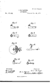
Figure l is an'elevation, and Fig. 2 is a vertical section, of a governor constructed according to my invention. Fig. 3 is a horizontal section taken on the line 1 l, Figs. l and 2.
A is the vessel which contains the fluid; B, the spindle to which it is fixed. The spindle B is pivoted at a, and has an upper bearing at a. The means shown for communicating rotation to the vessel A are a pulley on the spindle B, which receives a drivin g-band from a pulley driven in any convenient manner from the motive-power engine. The support ing-frame E is fastened to base-plate El, and carries the upper bearing bracket E, the bracket E3 for supporting the central fixed tube or vessel d, and the cylinder or tube F,
i in which `is the iloat I. The rack I1, which is fixed to iloat I, gears with the toothed sector I2. The iioat is guided by the upright I3. Gonnecting-rod I4 is jointed to the sector I2, and is part of the means shown for transmitting the movement of the float to the valve ofthe steam or other motive engine. On the vessel A being rotated, the tluid in the vessel passes in at the oriiicefat the end of the hollow arm e, which projects from the center fixed tube or vessel d. H are internal projections, which serve to enforce and sustain the rotation of the fluid as completely as possible in conformity with that of the vessel, and to insure the due 'pressure of the iiuid at the oricej', according to the speed of rotation. When sufficient speed of rotation is given to the vessel A the uid will rise in tube d until it reaches the float I. When a further increase of speed is given the oat I will be acted upon, and as the speed increases it will be raised. The instrument may be so connected with the engine it has to govern that when the engine is running at nearly its full speed the float I will be on the point of heilig raised, so that, on any increase in the speed, the valve of the engine will be operated to close through the connections already explained. As the speed of the engine, and consequently of the vessel A, diminishes, the oat I will fall, and the valve of the engine will be reopened. Small air-holes c c are provided. Fig. 4 shows the xed tube or vessel F required for the float I, placed so that it passes into the rotating vessel A. In this gure the oat I is shown assisted by the balance-weight J. The two are connected by a cord passing over a pulley, K, to which it is attached to prevent slip. The lever I4 and connecting-rod I5 are part of the means shown for transmitting the movement of the float to the valve of the steam or other motive-power engine. E represents a bracket or part of a supporting-frame. It is shown supporting the central cylinder or vessel F risin g lfrom the central tube d.
Figs. 5, 6, 7, 8. 9, and 10 represent various forms of projecting arms and orifices suited to my invention. In each figure, (l is the central fixed tube or vessel, e the hollow arm, and fthe orifice. In Figs. 9 and l0 the hollow arm c is shown projecting from the circular disk e',whicl1 operates to prevent the action of the full length of the arm against the fluid. In Figs. 9 and l0 a means is shown of reversing the oriticef from one side of the hollow arm i to the other, in order that, when desired, the vessel containing the fluid may be rotated in either direction. The reversing of the orifice f is obtained by the cylindrical valve q,which lits freely in the tube fr. This valve takes its position on one side or the other of the hollow in the arm e, according to the direction in which the uid is moved. The pins s form stops for the valves q.
In Figs. 11 and 12, d is the central tube, e the projecting arm, and f the orifice. 'These last figures represent a small-size arm and orilice. The sizes of the xed center tubes, the projecting arms, and orifices will depend upon the size of the instrument and the use for which it is destined.
The disk e', Figs. 9 and 10, may be used or not, as preferred, in conjunction with any of the forms of projecting arms e shown.
In indicating the similar parts on the various figures I have endeavored to use similar letters of reference, in order to render it unnecessary to repeat the explanation of such parts.
My rotating vessels may be filled with the lluid, or may sometimes be only partially lilled.
In arranging the drawings which illustrate my invention I have supposed mercury to be the fluid used.
More than one orifice, f, may be used, when desired, connected with the center xed tube or vessel d.
Having thus described the nature of my said invention, and the manner of performing the same, I would have it understood that I do not claim the mechanical parts separately; but
I claim- 1. A speed regulator or governor, consist ing of the combination, with valve-connections or actuating mechanism, of a rotating vessel adapted to contain and carry around with it mercury or other liquid; a stationary arm supported within the rotating vessel and provided with an orice 5 and a tube or vessel communicating bya channel with the orifice in the arm, into which orifice, and by way of the channel, the liquid is forced to the tube or vessel in which, by virtue of the pressure of the liquid at the orifice increasing with the speed of rotation of the vessel, it operates through said connections upon the throttle-valve or equivalent part of the engine to be controlled, substantially as described.
2. The combination, substantially as hereinbefore set forth, of the rotating vessel driven from the engine, the speed of which is to be controlled, and adapted to contain and carry around with it the mercury or other liquid, the cylinder or tube located above said vessel, the float in the cylinder, the hollow arms connected with the cylinder, projecting into the rotating vesseland having an orifice in its outer end, and mechanism, substantially such as described, for connecting said oat with the valve of the engine.
3. The combination of the cylinder or tube JAMES M. NAPIER.
Witnesses:
WILMER M. HARRIS, JNO. DEAN, Both of No. 17 Gracechmch street, London.
Publications (1)
| Publication Number | Publication Date |
|---|---|
| US185691A true US185691A (en) | 1876-12-26 |
Family
ID=2255097
Family Applications (1)
| Application Number | Title | Priority Date | Filing Date |
|---|---|---|---|
| US185691D Expired - Lifetime US185691A (en) | Improvement in governors |
Country Status (1)
| Country | Link |
|---|---|
| US (1) | US185691A (en) |
Cited By (1)
| Publication number | Priority date | Publication date | Assignee | Title |
|---|---|---|---|---|
| US2517955A (en) * | 1944-11-11 | 1950-08-08 | Automatic Steel Products Inc | Centrifugal mercury clutch |
-
0
- US US185691D patent/US185691A/en not_active Expired - Lifetime
Cited By (1)
| Publication number | Priority date | Publication date | Assignee | Title |
|---|---|---|---|---|
| US2517955A (en) * | 1944-11-11 | 1950-08-08 | Automatic Steel Products Inc | Centrifugal mercury clutch |
Similar Documents
| Publication | Publication Date | Title |
|---|---|---|
| US185691A (en) | Improvement in governors | |
| US1505791A (en) | Apparatus for separating liquids of different specific gravities and indicating means therefor | |
| US2701313A (en) | Air supply to turbine runners of hydroelectric power plants | |
| US1205127A (en) | Speed-governor. | |
| US1530740A (en) | Speed regulator | |
| US1150013A (en) | Boiler feed-governor. | |
| US1278077A (en) | Compensating meter. | |
| US1268130A (en) | Fluid-meter. | |
| US772294A (en) | Governor for hydraulic turbines. | |
| US439749A (en) | Boiler feeder and regulator | |
| US1033598A (en) | Liquid-meter. | |
| US1043115A (en) | Fluid-meter. | |
| US208149A (en) | Improvement in governors for steam-engines | |
| US27601A (en) | John stowell | |
| US736363A (en) | Marine-engine governor. | |
| US1698299A (en) | Governing mechanism for prime movers | |
| US537273A (en) | Dam per-regulator | |
| US867855A (en) | Apparatus for obtaining a uniform rate of flow of gases in pipe-conduits. | |
| US345754A (en) | Speed-controller | |
| US216556A (en) | Improvement in gas-regulators | |
| US95481A (en) | Improved governor for steam and other enginery | |
| US339415A (en) | Gas peessure govebnob | |
| US184653A (en) | Improvement in speed-indicators | |
| US864807A (en) | Boiler-feeder. | |
| US726175A (en) | Apparatus for governing fluid-pressure impulse-motors. |