US1856904A - Automatic bag holder and weigher - Google Patents
Automatic bag holder and weigher Download PDFInfo
- Publication number
- US1856904A US1856904A US500914A US50091430A US1856904A US 1856904 A US1856904 A US 1856904A US 500914 A US500914 A US 500914A US 50091430 A US50091430 A US 50091430A US 1856904 A US1856904 A US 1856904A
- Authority
- US
- United States
- Prior art keywords
- bag
- weigher
- bag holder
- automatic bag
- shaft
- Prior art date
- Legal status (The legal status is an assumption and is not a legal conclusion. Google has not performed a legal analysis and makes no representation as to the accuracy of the status listed.)
- Expired - Lifetime
Links
- 230000002093 peripheral effect Effects 0.000 description 3
- 235000002595 Solanum tuberosum Nutrition 0.000 description 2
- 244000061456 Solanum tuberosum Species 0.000 description 2
- 238000010276 construction Methods 0.000 description 2
- 210000002414 leg Anatomy 0.000 description 2
- 238000013459 approach Methods 0.000 description 1
- 210000001217 buttock Anatomy 0.000 description 1
- 210000003414 extremity Anatomy 0.000 description 1
- 235000012015 potatoes Nutrition 0.000 description 1
- 230000008707 rearrangement Effects 0.000 description 1
- 230000000630 rising effect Effects 0.000 description 1
- 230000035945 sensitivity Effects 0.000 description 1
- 239000000725 suspension Substances 0.000 description 1
- 238000005303 weighing Methods 0.000 description 1
Images


Classifications
-
- B—PERFORMING OPERATIONS; TRANSPORTING
- B65—CONVEYING; PACKING; STORING; HANDLING THIN OR FILAMENTARY MATERIAL
- B65B—MACHINES, APPARATUS OR DEVICES FOR, OR METHODS OF, PACKAGING ARTICLES OR MATERIALS; UNPACKING
- B65B1/00—Packaging fluent solid material, e.g. powders, granular or loose fibrous material, loose masses of small articles, in individual containers or receptacles, e.g. bags, sacks, boxes, cartons, cans, or jars
- B65B1/30—Devices or methods for controlling or determining the quantity or quality or the material fed or filled
- B65B1/32—Devices or methods for controlling or determining the quantity or quality or the material fed or filled by weighing
Definitions
- This invention relates to an improved apparatus in the nature of a bag holder which is expressly constructed for suspending a multiplicity of sacks, such as potato sacks in such a manner as to rapidly and successively bring the sacks into a position in alinement with a chute for expeditious filling purposes,
- My purpose is to provide a bag holding and filling apparatus of this kind constltuting a novel contribution to the art in that it possesses a practical and feasible arrangement of mechanical expedients so related as to msure efiiciency in use and operation, and exped1- tious handling, and to otherwise fulfill the desired results of a machine of this kind.
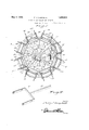
- Figure 1 is a top plan view of the complete assembly as made in accordance with the present invention.
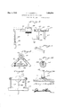
- Figure 2 is a central vertical section on the line 2-2 of Figure 1.
- FIG. 3 is a detail elevational View showing the novel latch equipped stop device.
- Figure 4 is a perspective view of one of the sack or bag hangers.
- Figure 5 is a sectional view taken approximately on the plane of the line 55 of F igure 1.
- Figure 6 is a detail section on the line 66 of Figure 2.
- Figure 7 is a fragmentary elevational view of the latch constituting the primary part of the stop device.
- Figure 8 is a horizontal section on the line 8-8 of Figure 2.
- Figure 9 is a perspective view of one of the details.
- Figure 10 is a section on the line 10-10 of so Figure 6.
- I Figure 11 is a perspective view of one of the scale arms or levers.
- Figure 12 is a horizontal section on the line 12-12 of Figure 2.
- Figure 13 is a detail section through the bag hanger attaching and supporting means.
- Figures 14 and 15 are sections on the lines 14:44 and 1515 respectively of Figure 2.
- the general assembly may well be seen in ca F igure 2.
- the relatively stationary stand is generally designated by the reference character 16 and this comprises a suitable base 17 and a plurality of upwardly directed and inwardly converging legs.18 connected as at their upper ends to a centralized tubular guide sleeve 19.
- the stop device is mounted here. It is generally designated by the reference character 20 and comprises a pair of upstanding arms 21 having an arch 22 attached to the upper ends thereof.
- the reference character 23 designates a fixed abutment on the arch while 24 designates an attaching bracket for a spring pressed brake shoe 25.
- This shoe is in the nature of a pivoted plate whose terminal is provided with a finger extending into a suitably fastened coil spring 26 located adjacent the horizontal extremity of the stop 23.
- the reference character 27 designates a bearing on the base plate on which the lower end of a vertical shaft 28 is mounted for rotation. On the lower end portion of this shaft, just above the bearing, is a friction drive disk 29. A friction drive wheel 30 cooperates with the peripheral portion thereof, this being carried by a shaft 31-journalled for rotation in a shield or housing 32 mounted on the base plate.
- the shaft 32 carries a large pulley 33 over which a belt 34 is trained.
- the belt is also trained over a pulley 35 on the shaft of the electric motor 36 and this provides the desired time drive and guard means therefor.
- the shaft 28 extends above the. guide sleeve 19 and above the latch means and at its upper end it carries a rotary head generally designated by the reference character 37 in 2.
- the head includes a spider-like radlal arm 38 connected to a peripheral rim 39. This rim carries the bag hanger and ad ustable scale lever means.
- This bag suspension and weighing means is composed of a plurality of successively operable devices which may be generally or 1ndividually referred to as bag holders.
- Each ba holder is the same in construction, and a fescription of one will suffice for all. Proceeding with this in mind, I first call attention to a pair of upstanding lugs 40 (see Fig. 13) fastened to the rim at spaced points.
- each lever serves as supports for the yoke 41 (see Figure 11) of the scale lever arm 42.
- the arm portions of the yoke are pivoted as at 43 to the upper ends of the lugs in Figure 13.
- the scale levers are rockably mounted between their ends.
- the inner end of each lever has a depending bracket 44 which may be referred to as a trip and this cooperates with the spring-pressed latch and stop means already described.
- the reference character 45 desi nates a slidable weight which as seen in igure 10 is held in different positions through the medium of a set screw 46..
- the reference character 47 represents generally a vertically suspended bag hanger (see Figure 4) which accommodates the sack or bag 48. At the upper end of this hanger is a U-shaped member 49 having corner spurs 50 over which the corners of the bag are en aged as represented in dotted lines.
- the lever just described functions somewhat as a scale beam as is evident in Figure 6, and the leverage is adjusted in sensitivity by the slidable weight 45.
- the bag is on one end of the beam and the trips 44 on the opposite end of the beam in a position to engage the stop device 20 as seen in Figure 2.
- the bags are suspended on the various hangers in an obvious manner, and when the motor'ds set inoperation, the shaft 28 is turned through the medium of the friction driving disc 30 and the complemental wheel 30 (see Figure 2). Assuming that the potato or merchandise chute is located in alinement with the stop device 20 it will be seen that the bags will thus be brought successively into registry with the chute for filling.
- the latch 25 functions somewhat as a brake shoe as the trip 44 approaches the stop 23 in Figure 7. In other words, it acts as a drag which slows up the rotation of the head to avoid a stop which would be too abrupt.
- said trip first engaging the spring-pressed latch which acts as a brake of the rotary part, after which the trip engages the stop which holds the outward part against movement, until the bag is filled and the tilting of the beam moves the trip out of engagement with the stop.
- a stand comprising a base, legs rising from and disposed in in- Wardly converging relationship on said base, and connected at their upper ends to a guide sleeve, said guide sleeve being centrally arranged, a bearing on the base beneath said guide sleeve, a shaft mounted for rotation in said bearing and extending upwardly through said sleeve, a drive disk carried by said shaft and located just above the bearing, an electric motor on said base, and a friction drive Wheel connected with said Inotor and cooperable with the peripheral portion of said disc, a bag carrier on the upper end of said shaft, and co-acting means between the stand and carrier for causing intermittent rotation of the carrier, While a1- lowing continuous operation of the disc and motor.
Landscapes
- Engineering & Computer Science (AREA)
- Quality & Reliability (AREA)
- Mechanical Engineering (AREA)
- Holders For Apparel And Elements Relating To Apparel (AREA)
Description
May 3, 1932.
nvenior Pwrzymf JQw QZ&ZZ
Q By Attorney I y 2- P J CAMPBELL 1,856,904
AUTOMATIC BAG HOLDER AND WEIGHER Filed Dec. 8, 1930 4 Sheets-Sheet 2 Inventor iiyjf m viiz By 2mm I A itomey May 3, 1932.
P. J. CAMPBELL 1,856,904
AUTOMATIC BAG HOLDER AND WEIGHER Filed Dec. 8, 1930 4 Sheets-Sheet 3 Er JJ/ m uZe&Z-
By fizwaozw A iiorney May 3, 1932.
P. J. CAMPBELL AUTOMATIC BAG HOLDER AND WEIGHER Filed Dec. 8, 1930 4 Sheets-Sheet 4 Inventor ,7 a/rry J62. v/vJeZZ Attorney Patented May 3, 1932 UNITED STATES PATENT OFFICE PARRY J'. CAJHEPIBIELL, F BOYNE CITY, MIQEZEGAN, ASSIGNOR OF ONE-HALF T0 13'. WESLEY DILWORTH, 6F BOYNE CITY, MICHIGAN AUTOMATIC BAG- HQL'DER AND WEIGHER Application filed December a, 19cc. Serial m. 500,914.
This invention'relates to an improved apparatus in the nature of a bag holder which is expressly constructed for suspending a multiplicity of sacks, such as potato sacks in such a manner as to rapidly and successively bring the sacks into a position in alinement with a chute for expeditious filling purposes,
In'ac'cordance with my inventive conception, I have evolved and developed a novel structural apparatus of this class which is characterized by a relatively stationary stand, and an electric motor drlven rotary carrier supported on said stand, said earner being mechanically distinguishable, in that it is individualized by the presence of a mat tiplicity of separate rockably mounted scale beams having suitable bag hangers thereon. 1
My purpose is to provide a bag holding and filling apparatus of this kind constltuting a novel contribution to the art in that it possesses a practical and feasible arrangement of mechanical expedients so related as to msure efiiciency in use and operation, and exped1- tious handling, and to otherwise fulfill the desired results of a machine of this kind.
In the drawings:
Figure 1 is a top plan view of the complete assembly as made in accordance with the present invention.
Figure 2 is a central vertical section on the line 2-2 of Figure 1.
Figure 3 is a detail elevational View showing the novel latch equipped stop device.
Figure 4 is a perspective view of one of the sack or bag hangers.
Figure 5 is a sectional view taken approximately on the plane of the line 55 of F igure 1.
Figure 6 is a detail section on the line 66 of Figure 2.
Figure 7 is a fragmentary elevational view of the latch constituting the primary part of the stop device.
Figure 8 \is a horizontal section on the line 8-8 of Figure 2.
Figure 9 is a perspective view of one of the details.
Figure 10 is a section on the line 10-10 of so Figure 6. I Figure 11 is a perspective view of one of the scale arms or levers. Figure 12 is a horizontal section on the line 12-12 of Figure 2.
Figure 13 is a detail section through the bag hanger attaching and supporting means.
Figures 14 and 15 are sections on the lines 14:44 and 1515 respectively of Figure 2.
The general assembly may well be seen in ca F igure 2. Here the relatively stationary stand is generally designated by the reference character 16 and this comprises a suitable base 17 and a plurality of upwardly directed and inwardly converging legs.18 connected as at their upper ends to a centralized tubular guide sleeve 19. The stop device is mounted here. It is generally designated by the reference character 20 and comprises a pair of upstanding arms 21 having an arch 22 attached to the upper ends thereof. By referring to Figure 7,. it Will be seen that the reference character 23 designates a fixed abutment on the arch while 24 designates an attaching bracket for a spring pressed brake shoe 25. This shoe is in the nature of a pivoted plate whose terminal is provided with a finger extending into a suitably fastened coil spring 26 located adjacent the horizontal extremity of the stop 23.
The reference character 27 designates a bearing on the base plate on which the lower end of a vertical shaft 28 is mounted for rotation. On the lower end portion of this shaft, just above the bearing, is a friction drive disk 29. A friction drive wheel 30 cooperates with the peripheral portion thereof, this being carried by a shaft 31-journalled for rotation in a shield or housing 32 mounted on the base plate.
By referring to Figure 15, it will be observed that the shaft 32 carries a large pulley 33 over which a belt 34 is trained. The belt is also trained over a pulley 35 on the shaft of the electric motor 36 and this provides the desired time drive and guard means therefor.
The shaft 28 extends above the. guide sleeve 19 and above the latch means and at its upper end it carries a rotary head generally designated by the reference character 37 in 2. The head includes a spider-like radlal arm 38 connected to a peripheral rim 39. This rim carries the bag hanger and ad ustable scale lever means.
This bag suspension and weighing means is composed of a plurality of successively operable devices which may be generally or 1ndividually referred to as bag holders. Each ba holder is the same in construction, and a fescription of one will suffice for all. Proceeding with this in mind, I first call attention to a pair of upstanding lugs 40 (see Fig. 13) fastened to the rim at spaced points.
These lugs serve as supports for the yoke 41 (see Figure 11) of the scale lever arm 42. The arm portions of the yoke are pivoted as at 43 to the upper ends of the lugs in Figure 13. Thus the scale levers are rockably mounted between their ends. The inner end of each lever has a depending bracket 44 Which may be referred to as a trip and this cooperates with the spring-pressed latch and stop means already described.
Then too, the reference character 45 desi nates a slidable weight which as seen in igure 10 is held in different positions through the medium of a set screw 46..
The reference character 47 represents generally a vertically suspended bag hanger (see Figure 4) which accommodates the sack or bag 48. At the upper end of this hanger is a U-shaped member 49 having corner spurs 50 over which the corners of the bag are en aged as represented in dotted lines.
The lever just described functions somewhat as a scale beam as is evident in Figure 6, and the leverage is adjusted in sensitivity by the slidable weight 45. Thus the bag is on one end of the beam and the trips 44 on the opposite end of the beam in a position to engage the stop device 20 as seen in Figure 2.
In operation, the bags are suspended on the various hangers in an obvious manner, and when the motor'ds set inoperation, the shaft 28 is turned through the medium of the friction driving disc 30 and the complemental wheel 30 (see Figure 2). Assuming that the potato or merchandise chute is located in alinement with the stop device 20 it will be seen that the bags will thus be brought successively into registry with the chute for filling.
As seen in Figure 3, as each bag holder comes around into alinement with the stop device, the depending trip member 44 rides up on the spi'ingz pressed shoe or latch 25 as represented in igure 7. It depresses the spring sufliciently so that it becomes seated between the stop 23 and the free end of the latch 25 as represented in dotted lines in Fi ure 2. This therefore, stops rotation of t e head 37 momentarily and allows the bag to remain put until filled.
The adjustment of the weight or scale beam has already been made. Therefore, as soon as the bag fills, it overbalances the weighted end of the lever as seen in Figure 6, thus lifting the trip 44 and allowing the motor drive to come into play to turn the filled bag away and to bring up the next bag for filling. This operation is repeated, thus permitting the bags to be successively and expeditiously filled with the goods, such as potatoes or the like,
The latch 25 functions somewhat as a brake shoe as the trip 44 approaches the stop 23 in Figure 7. In other words, it acts as a drag which slows up the rotation of the head to avoid a stop which would be too abrupt.
A careful consideration of the description in connection with the drawings will enable the reader to obtain a clear understanding of the construction, the operation, and the features and advantages of the apparatus. Therefore, a more lengthy description is regarded as unnecessary.
Minor changes in shape, size, and rearrangement of details coming within the field of invention claimed may be resorted to in actual practice if desired.
I claim 1. In a bag holding and filling apparatus at the opposite end, said trip first engaging the spring-pressed latch which acts as a brake of the rotary part, after which the trip engages the stop which holds the outward part against movement, until the bag is filled and the tilting of the beam moves the trip out of engagement with the stop.
2. In a bag holding and filling apparatus of the class described, a stand comprising a base, legs rising from and disposed in in- Wardly converging relationship on said base, and connected at their upper ends to a guide sleeve, said guide sleeve being centrally arranged, a bearing on the base beneath said guide sleeve, a shaft mounted for rotation in said bearing and extending upwardly through said sleeve, a drive disk carried by said shaft and located just above the bearing, an electric motor on said base, and a friction drive Wheel connected with said Inotor and cooperable with the peripheral portion of said disc, a bag carrier on the upper end of said shaft, and co-acting means between the stand and carrier for causing intermittent rotation of the carrier, While a1- lowing continuous operation of the disc and motor.
In testimony whereof I affix my signature.
PARRY J. CAMPBELL.
Priority Applications (1)
| Application Number | Priority Date | Filing Date | Title |
|---|---|---|---|
| US500914A US1856904A (en) | 1930-12-08 | 1930-12-08 | Automatic bag holder and weigher |
Applications Claiming Priority (1)
| Application Number | Priority Date | Filing Date | Title |
|---|---|---|---|
| US500914A US1856904A (en) | 1930-12-08 | 1930-12-08 | Automatic bag holder and weigher |
Publications (1)
| Publication Number | Publication Date |
|---|---|
| US1856904A true US1856904A (en) | 1932-05-03 |
Family
ID=23991449
Family Applications (1)
| Application Number | Title | Priority Date | Filing Date |
|---|---|---|---|
| US500914A Expired - Lifetime US1856904A (en) | 1930-12-08 | 1930-12-08 | Automatic bag holder and weigher |
Country Status (1)
| Country | Link |
|---|---|
| US (1) | US1856904A (en) |
Cited By (3)
| Publication number | Priority date | Publication date | Assignee | Title |
|---|---|---|---|---|
| US2580993A (en) * | 1948-10-20 | 1952-01-01 | T R Mantes | Weighing machine |
| US2642276A (en) * | 1952-02-23 | 1953-06-16 | Martin B Monson | Weighing and packaging machine |
| US2733040A (en) * | 1956-01-31 | Bag filling machine |
-
1930
- 1930-12-08 US US500914A patent/US1856904A/en not_active Expired - Lifetime
Cited By (3)
| Publication number | Priority date | Publication date | Assignee | Title |
|---|---|---|---|---|
| US2733040A (en) * | 1956-01-31 | Bag filling machine | ||
| US2580993A (en) * | 1948-10-20 | 1952-01-01 | T R Mantes | Weighing machine |
| US2642276A (en) * | 1952-02-23 | 1953-06-16 | Martin B Monson | Weighing and packaging machine |
Similar Documents
| Publication | Publication Date | Title |
|---|---|---|
| ES196150U (en) | Structure for construction. (Machine-translation by Google Translate, not legally binding) | |
| US1856904A (en) | Automatic bag holder and weigher | |
| US1711587A (en) | Rotatable display stand | |
| US1601247A (en) | Apparatus for the production and maintenance and utilization of vibratory motion | |
| US2843988A (en) | Apparatus for opening bags | |
| US2057284A (en) | Fruit packer's stand | |
| US2373649A (en) | Fruit bagger and weigher | |
| US2529438A (en) | Automatic magazine phonograph | |
| US2658761A (en) | Sound reproducing machine | |
| US1912509A (en) | Ladder | |
| US819930A (en) | Bagging and weighing machine. | |
| US2641459A (en) | Weighing apparatus | |
| US1535382A (en) | Air-bag puller | |
| US1379161A (en) | Bottle-capping machine | |
| US1655134A (en) | Fruit and vegetable packing apparatus | |
| US2439104A (en) | Amusement device | |
| US2894648A (en) | Stacking device | |
| US1932662A (en) | Machine for grading eggs by weight | |
| US1625057A (en) | Carton-feeding machine | |
| US321209A (en) | gladish | |
| US1920936A (en) | Phonograph | |
| US1374975A (en) | Collar-packaging machine | |
| US1104138A (en) | Toy weighing-machine. | |
| US1385559A (en) | Revolving toy | |
| US1567126A (en) | Bottle-filling apparatus |