US1856903A - Windlass and capstan driving mechanism - Google Patents
Windlass and capstan driving mechanism Download PDFInfo
- Publication number
- US1856903A US1856903A US431237A US43123730A US1856903A US 1856903 A US1856903 A US 1856903A US 431237 A US431237 A US 431237A US 43123730 A US43123730 A US 43123730A US 1856903 A US1856903 A US 1856903A
- Authority
- US
- United States
- Prior art keywords
- shaft
- windlass
- pinion
- gear wheel
- gear
- Prior art date
- Legal status (The legal status is an assumption and is not a legal conclusion. Google has not performed a legal analysis and makes no representation as to the accuracy of the status listed.)
- Expired - Lifetime
Links
- 230000007246 mechanism Effects 0.000 title description 23
- 230000005540 biological transmission Effects 0.000 description 9
- RNAMYOYQYRYFQY-UHFFFAOYSA-N 2-(4,4-difluoropiperidin-1-yl)-6-methoxy-n-(1-propan-2-ylpiperidin-4-yl)-7-(3-pyrrolidin-1-ylpropoxy)quinazolin-4-amine Chemical compound N1=C(N2CCC(F)(F)CC2)N=C2C=C(OCCCN3CCCC3)C(OC)=CC2=C1NC1CCN(C(C)C)CC1 RNAMYOYQYRYFQY-UHFFFAOYSA-N 0.000 description 3
- 230000008901 benefit Effects 0.000 description 3
- 238000010276 construction Methods 0.000 description 3
- 241000282327 Felis silvestris Species 0.000 description 2
- 230000009471 action Effects 0.000 description 2
- 230000008878 coupling Effects 0.000 description 2
- 238000010168 coupling process Methods 0.000 description 2
- 238000005859 coupling reaction Methods 0.000 description 2
- 239000000314 lubricant Substances 0.000 description 2
- 235000017858 Laurus nobilis Nutrition 0.000 description 1
- 241001544487 Macromiidae Species 0.000 description 1
- 235000005212 Terminalia tomentosa Nutrition 0.000 description 1
- 244000125380 Terminalia tomentosa Species 0.000 description 1
- 239000003795 chemical substances by application Substances 0.000 description 1
- 210000004907 gland Anatomy 0.000 description 1
- 238000009434 installation Methods 0.000 description 1
- 238000012856 packing Methods 0.000 description 1
- 230000001737 promoting effect Effects 0.000 description 1
- 230000009467 reduction Effects 0.000 description 1
Images
Classifications
-
- B—PERFORMING OPERATIONS; TRANSPORTING
- B66—HOISTING; LIFTING; HAULING
- B66D—CAPSTANS; WINCHES; TACKLES, e.g. PULLEY BLOCKS; HOISTS
- B66D1/00—Rope, cable, or chain winding mechanisms; Capstans
- B66D1/26—Rope, cable, or chain winding mechanisms; Capstans having several drums or barrels
-
- B—PERFORMING OPERATIONS; TRANSPORTING
- B66—HOISTING; LIFTING; HAULING
- B66D—CAPSTANS; WINCHES; TACKLES, e.g. PULLEY BLOCKS; HOISTS
- B66D2700/00—Capstans, winches or hoists
- B66D2700/01—Winches, capstans or pivots
- B66D2700/0125—Motor operated winches
- B66D2700/0166—Winches with multiple drums or with drums with multiple parts of different diameter
-
- Y—GENERAL TAGGING OF NEW TECHNOLOGICAL DEVELOPMENTS; GENERAL TAGGING OF CROSS-SECTIONAL TECHNOLOGIES SPANNING OVER SEVERAL SECTIONS OF THE IPC; TECHNICAL SUBJECTS COVERED BY FORMER USPC CROSS-REFERENCE ART COLLECTIONS [XRACs] AND DIGESTS
- Y10—TECHNICAL SUBJECTS COVERED BY FORMER USPC
- Y10T—TECHNICAL SUBJECTS COVERED BY FORMER US CLASSIFICATION
- Y10T74/00—Machine element or mechanism
- Y10T74/19—Gearing
- Y10T74/19023—Plural power paths to and/or from gearing
- Y10T74/19074—Single drive plural driven
- Y10T74/19079—Parallel
- Y10T74/19084—Spur
Definitions
- Figure 2 is a vertical cross-section of the same on the line 2,2, of Figure 3, certain parts being indicated in side view.
- Figure 3 is a horizontal section on 3, 3, of Figure 2. 7
- Figure 4 is a side elevation of a ships windlass and capstan, with an outside view the line of my improved mechanism for operating the same.-
- a variable speed driven pump in the marine installations above referred to is often actuated by a variable speed electrically driven driving pump; but these power machines do not form a part of the present invention, and I do not consider it necessary to describe or illustrate the same furthervtha-n I have already done; and it will be understood that the pump 1 stands to represent any kind of motor, engine, or other power appliance to drive a windlass andcapstan, singly or jointly, or other mechanism, through the connecting novel system of gearing; which I shall now set forth in detail. 7
- FIG 4 I have shown a windlass and a capstan so as to indicate their relation to the mechanism that drives them
- a partial cross-section of a ship is depicted in outline, A being one deck on which the windlass D and capstan C may be supported, and E being a lower deck on which the ma chinery for driving these and similar devices may be carried.
- the decks are represented simplyto assist in the explanation.
- the windlass D has a revolvable member, called the wildcat in nautical language, which is provided with teeth 03 that are adaptor other mechanism,
- capstan C is adjacent to the Windlass C on deck A, and it has its drnmikeyed or .fastenedto .a vertical driving shaft 21 therefor, carried in some suitable bearing in deck A; and-shaft 21 is connected by a coupling 22 to a shaft 14 vertically beneath'it,'so that the -two shafts 21 and :la together constitute a continuous member, said shaft .14 carrying .a part of the gear transmission mechanism, as .I shall explain.
- a pressing problem in connection with the driving mechanism for vthe windlasses and capstans of vessels has been that of reducing the cost of construction and promoting the ease .and :speed .of the operation of such mechanisms.
- Said driving means 1 is mounted upright in a -faame 3, on the cover 2a ofa-gearcasing L2,, supported on frame 4, that .is mounted on bed frame B, secured to deck E, see Figure .1, the said arrangement beingonly an example of convenient means for localizing these parts in effective relation to the gear- Vertical shaft -5 passes through a bearing -31 in cover 2a into the interior of casing 2 which is filled with oil in which the gears may run and be thoroughly lubricated.
- Shaft 5 has keyed thereon a wide pinion -6 that engages and drives two horizontal gear wheels 7,7, "which vlie in the same horizontal --plane and are respectively keyed firmly to short ,paral-l'el vertical sha-fts 8, .8, which are oarriedin upperbeari-ngs 32, 32, in the cover member 2a -and in lower bearings 33, '33, in the bottom of casing 2.
- the capstan shaft 14l that is driven :by-gear wheel113 hasa bearing 37 in the frame cover .2aandalowerstep bearing 38 in the bottom of casing2 and top part of frame 4,.see Figure :1.
- the windlassaactuatingshaifit 15 .issupported at its lower-end in abear'ing 39 in the base B.
- On shaft 15 is a large gear Said zgear wheel is loose on shaft l5,a.nd is not in the lubricant casing, but outside of same, asis ,pinion .1'0, but gear .16 is prefer- .roller bearings, gaskets, glands, or other forms of packing to make the running the easiest possible.
- a horizontal locking head or wheel 20 Keyed to the shaft 15 above the loose gear wheel 16 is a horizontal locking head or wheel 20, see Figure 1.
- the upper surface of gear wheel 16 is provided with a circular series of rectangular or other openings 28, see Fig ure 3, adapted to be entered by a pair of locking block keys 23.
- These keys are raised and lowered so as to be caused to engage with or be disengaged from two or more of the openings 28 by means of a ring 25, which loosely surrounds a fiange30 on wheel 20 and is'kept in place by small plates 27 that overlap and cover the same, said ring 25 being moved and adjusted around the flange 30 by using a bar or handle that is inserted in one or more of the openings 26 in the side of ring 25.
- Ring 25 further has a couple of inclined ribs 29 that engage notches in the locking blocks 23.
- the blocks 23 may be lowered through their holders 24 on wheel 20 down into or raised up out of holes 28, and thus connection be made or broken between members 16 and 20, so that the train of parts may be active to drive the windlass or may be thrown out of action to make the windlass idle.
- the combination with driving means and driven means, of transmission mechanism connecting them and consisting essentially of a shaft, a gear wheel loose thereon, means for locking it thereto, a second shaft parallel to the first, a pinion thereon, a pair of combined gear wheels and pinions, of which the gear wheels lie in the same plane and are engaged by the said pinion on the second shaft, a third shaft in line with the second shaft, a gear wheel on the third shaft engaged by the two pinions of the combined wheels, a pinion on said third shaft that engages the gear wheel on the first shaft, a fourth shaft parallel to the other shafts 5 and a gear wheel on the fourth shaft that is engaged by the intermediate gear wheel on the third shaft.
- a transmission mechanism for the operation of plural driven means jointly or independently as described two parallel shafts that transmit power to different driven means, a gear wheel loose on one shaft, means for locking it thereto, a gear wheel fast on the other shaft, and an intermediate train of gearing and other parts, consisting of a power-driven pinion, a pair of combined gear wheels and pinions of which the gear wheels lie in the same lane and are engaged by the power-driven pinion, an intermediate gear wheel engaged by the two pinions of the combined wheels and itself engaging the gear wheel fast on one driving shaft, and a pinion engaging and driving the aforesaidloose gear wheel and having a journal that carries the aforesaid intermediate gear wheel.
Landscapes
- Engineering & Computer Science (AREA)
- Mechanical Engineering (AREA)
- Gear Transmission (AREA)
Description
May 3, 1932. s. E. BARRETT I WINDLASS AND CAI STAN DRIVING MECHANISM Filed Feb. 25. 1930 3 Sheets-Sheet May 3, 1932. G. E. BARRETT WINDLASS AND CAPSTAN DRIVING MECHANISM Filed Feb. 25,- 1930 3 Sheets-Sheet 2 2 2 m G999 G096 Q In ran i L/III I I My yll ll/llllllllllllllllllllllllllll/j/l/ ATTORNEY May 3, 1932. G. E. BARRETT WINDLASS AND CAPSTAN DRIVING MECHANISM Filed Feb. 25. I930 I5 Sheets-Sheet 3 ATTORN Patented May 3, 1932 UNITED STATES PATENT OFFICE GEORGE EUGENE BARRETT, 0F LAUREL SPRINGS, N EW'JERSEY WINDLASS AND GAPSTAN DRIVING MECHANISM Application filed February 25, 1930. Serial No. 431,237.
space and in the cost of machine construction, besides concentrating and compacting the transmission machinery in a small compass, so as to secure greater strength, easier and quicker manipulation, fewer and smaller gears, a more powerful action, and surer and more accurate results, and numerous other advantages over more complicated mecha nisms now. in use.
With these and numerous other objects in view the invention may be said to consist essentially in the construction, combination, and arrangement of parts, substantially as will be hereinafter more fully described, and then pointedout in the ensuing clauses of claims.
For convenience in explanation, I have selected a windlass and capstan, or similar appliances, and their driving mechanism, in use generally today on many battleships, cruisers and other vessels, not because my invention restricts me to a combination of my simplified gear transmission with such machinery, but because it will be commonly used therewith, though it will be obvious that it may be used with other classes of machines.
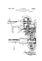
Such driving mechanisms commonly in Figure 1 is side elevation vpartly in section of my improved gear transmission system for actuating windlasses and capstans and similar devices, the same being taken on the line 1, 1, of Figure 3. I i
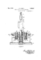
Figure 2 is a vertical cross-section of the same on the line 2,2, of Figure 3, certain parts being indicated in side view.
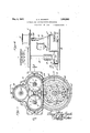
Figure 3 is a horizontal section on 3, 3, of Figure 2. 7
Figure 4 is a side elevation of a ships windlass and capstan, with an outside view the line of my improved mechanism for operating the same.-
Like characters of reference denote like parts in all the different'figures of the drawings.
1 denotes the outline of a driven pump, which itself constitutes a driving agency for. a windlass and capstan, through the intervening simplified gear transmission which. forms the subject matter of my present invention. A variable speed driven pump in the marine installations above referred to is often actuated by a variable speed electrically driven driving pump; but these power machines do not form a part of the present invention, and I do not consider it necessary to describe or illustrate the same furthervtha-n I have already done; and it will be understood that the pump 1 stands to represent any kind of motor, engine, or other power appliance to drive a windlass andcapstan, singly or jointly, or other mechanism, through the connecting novel system of gearing; which I shall now set forth in detail. 7
In Figure 4 I have shown a windlass and a capstan so as to indicate their relation to the mechanism that drives them, In Figure 4 a partial cross-section of a ship is depicted in outline, A being one deck on which the windlass D and capstan C may be supported, and E being a lower deck on which the ma chinery for driving these and similar devices may be carried. The decks are represented simplyto assist in the explanation.
The windlass D has a revolvable member, called the wildcat in nautical language, which is provided with teeth 03 that are adaptor other mechanism,
. ingsystem.
ed to be engaged by the anchor chain, said wildcat being secured to a vertical shaft 18 by means of which it is rotated. Shaft 18 is connected by a coupling 19 to a shaft 15 vertically beneath it, so that the two shafts 15 and 18 together constitute a continuous member, said shaft 15 carrying a part of the gear transmission, as I shall narrate in detail hereafter. Likewise the capstan C is adjacent to the Windlass C on deck A, and it has its drnmikeyed or .fastenedto .a vertical driving shaft 21 therefor, carried in some suitable bearing in deck A; and-shaft 21 is connected by a coupling 22 to a shaft 14 vertically beneath'it,'so that the -two shafts 21 and :la together constitute a continuous member, said shaft .14 carrying .a part of the gear transmission mechanism, as .I shall explain.
A pressing problem in connection with the driving mechanism for vthe windlasses and capstans of vessels has been that of reducing the cost of construction and promoting the ease .and :speed .of the operation of such mechanisms.
Heretofore such mechanism has been complicated and burdensome. In
any former Letters-Patent granted on July .5, 19.27, No. 1,634,766, I showed how a substantial reduction in the number of 1: arts and a more compactiarrange-mentof the'same would secure substantial benefits in many places. In my present improvements I-offer -a further simplification of mechanism to subserve other and additional distinct advantages. The simple form of gearing .I now utilize will be described in the followdlhe specimen driving agent .1, which may heat pump if desired, has .a vertical shaft "5. Said driving means 1 is mounted upright in a -faame 3, on the cover 2a ofa-gearcasing L2,, supported on frame 4, that .is mounted on bed frame B, secured to deck E, see Figure .1, the said arrangement beingonly an example of convenient means for localizing these parts in effective relation to the gear- Vertical shaft -5 passes through a bearing -31 in cover 2a into the interior of casing 2 which is filled with oil in which the gears may run and be thoroughly lubricated. Shaft 5 has keyed thereon a wide pinion -6 that engages and drives two horizontal gear wheels 7,7, "which vlie in the same horizontal --plane and are respectively keyed firmly to short ,paral-l'el vertical sha-fts 8, .8, which are oarriedin upperbeari- ngs 32, 32, in the cover member 2a -and in lower bearings 33, '33, in the bottom of casing 2. These parallel short shafts 8 have wide verticalpinionsi9,19,thereon, -one-on;.each, which are directly below the gear wheels 7., 7, so't'hat said gears and .9 and shafts 8 constitute a pair of units, the upper and ilowerends of each shaft 8 serving as journals .and turning easily in the bear- 'ithe ilowerend Mof-shaft This end 34 is reduced in size and has a bearing in the upper cndof a short vertical'shaft 11, to which the gear wheel 12 is secured; and said shaft 11 has an upperbearing 35 in the bottom of casing .2, and a lower step bearing 36 supported in the bed :plate B. Shaft .11 carries a large wide pinion 10 which .is below casing 2 and outside of it. All of .these gears which I have described, except gear'or pinion .10., are
enclosed .in casing2and .runin the oil there- 111. In 'sa1d case is .alsoanother gear wheel .13, on the capstansha-ft 14,:and gear 13 is in the same horizontal plane as gear 12 and meshes with and isdrliven by the gear wheel 12 which .is on shaft 11 .as already described. The casing2, as seen in Figure 3, isofa suitable shape to easily accommodate these gears therein and provide a lubricant cham- 13612; andthe cover2a is built to provide the necessary bearings as described and is secured on the casing in anydesiredmanner.
The capstan shaft 14l that is driven :by-gear wheel113 hasa bearing 37 in the frame cover .2aandalowerstep bearing 38 in the bottom of casing2 and top part of frame 4,.see Figure :1. And the windlassaactuatingshaifit 15 .issupported :at its lower-end in abear'ing 39 in the base B. On shaft 15 is a large gear Said zgear wheel is loose on shaft l5,a.nd is not in the lubricant casing, but outside of same, asis ,pinion .1'0, but gear .16 is prefer- .roller bearings, gaskets, glands, or other forms of packing to make the running the easiest possible.
The journal 3i :on the lower end of pinion 6 revolves in a bearing 40 .in the upper end of shaft 11. In Figure2 the grouping of all thegears and pinions from :pinion .6 to pinion 10 is shown clearly, and Figure 3.further discloses the relative arrangement .and operation very helpfully. The whole arrangement of gears is light :and strong. v.As the pinion .6 drives thetwo gears 8, the tooth load is divided in half, and this .allowsthe use of smaller gears and a more compact arrangement than would be :possible if heavy gears were required, The ,pinion 6 drives the ftWO gears8, to which the pinionsat) are secured;
.wheel 16 that is driven by :the .pinion 1'0.
and they in turn rotate the intermediate gear wheel 12 located directly below the pinion 6 and on a pinion shaft 11, so that pinion 10, which is directly in a vertical line with gear wheel 12 and pinion 6, becomes the transmitting power pinion to engage with and actuate the large windlass-driving gear wheel 16.
I will now explain the devices for locking the windlass shaft 15 to the large loose driving gear wheel 16, so that pump or motor 1 will drive shaft 15, and shaft 18 coupled to shaft 15, and drive windlass D. In the combination shown and described the driving mechanism is connected with the capstan C so as to operate the latter whenever motor 1 is running, but in order to operate the windlass D at the same time with capstan C the large loose gear 16 must be fastened to the windlass shaft so as to drive the latter. In the specific example given therefore the windlass and capstan may be driven together or the capstan may be driven separately. Obviously by the use of another clutch the cap stan might be declutched to allow the windlass to be driven when the capstan is quiet.
Keyed to the shaft 15 above the loose gear wheel 16 is a horizontal locking head or wheel 20, see Figure 1. The upper surface of gear wheel 16 is provided with a circular series of rectangular or other openings 28, see Fig ure 3, adapted to be entered by a pair of locking block keys 23. These keys are raised and lowered so as to be caused to engage with or be disengaged from two or more of the openings 28 by means of a ring 25, which loosely surrounds a fiange30 on wheel 20 and is'kept in place by small plates 27 that overlap and cover the same, said ring 25 being moved and adjusted around the flange 30 by using a bar or handle that is inserted in one or more of the openings 26 in the side of ring 25. Ring 25 further has a couple of inclined ribs 29 that engage notches in the locking blocks 23. Thus by rotating ring 25 more or less the blocks 23 may be lowered through their holders 24 on wheel 20 down into or raised up out of holes 28, and thus connection be made or broken between members 16 and 20, so that the train of parts may be active to drive the windlass or may be thrown out of action to make the windlass idle.
What I claim, is:
1. In a mechanism of the character described, the combination with driving means and driven means, of transmission mechanism connecting them, and consisting essentially of a shaft, a gear wheel loose thereon, means for locking it thereto, a second shaft parallel to the first, a pinion thereon, a pair of combined gear wheels and pinions, of which the gear wheels lie in the same plane and are engaged by the said pinion on the second shaft, a third shaft in line with the second shaft, a gear wheel on the third shaft engaged by the two pinions of the combined wheels, a pinion on said third shaft that engages the gear wheel on the first shaft, a fourth shaft parallel to the other shafts 5 and a gear wheel on the fourth shaft that is engaged by the intermediate gear wheel on the third shaft.
2. In a transmission mechanism for the operation of plural driven means jointly or independently as described, two parallel shafts that transmit power to different driven means, a gear wheel loose on one shaft, means for locking it thereto, a gear wheel fast on the other shaft, and an intermediate train of gearing and other parts, consisting of a power-driven pinion, a pair of combined gear wheels and pinions of which the gear wheels lie in the same lane and are engaged by the power-driven pinion, an intermediate gear wheel engaged by the two pinions of the combined wheels and itself engaging the gear wheel fast on one driving shaft, and a pinion engaging and driving the aforesaidloose gear wheel and having a journal that carries the aforesaid intermediate gear wheel.
3. In a transmission mechanism of the class described, the combination of two parallel shafts, a windlass and a capstan, means connecting one of the shafts with the windo on the other shaft, a power-driven pinion, a.
shaft on which it is carried, a pair of combined gear wheels and pinions'and their journals, the gear wheel members thereof being engaged by the power-driven pinion, an intermediate gear wheel engaged by-the pinion members of the combined wheels, said intermediate gear wheel engaging the aforesaid fast gear wheel'on one of the shafts, a shaft carrying said intermediate gear wheel, and a pinion on said shaft in mesh with the loose gear wheel.
l. In a mechanism of the character described, the combination of a windlass and a capstan, two parallel shafts, one of which drives the windlass and the other the capstan, a loose gear wheel on the windlass shaft, means for locking it thereto, a gear wheel fast on the capstan shaft, a power-driven pinion, a third shaft therefor, a pair of combined gear wheels and pinions whose gear members are situated in the same plane and in mesh with the aforesaid pinion, an intermediate gear wheel in mesh with the pinion members GEORGE EUGENE BARRETT.
Priority Applications (1)
| Application Number | Priority Date | Filing Date | Title |
|---|---|---|---|
| US431237A US1856903A (en) | 1930-02-25 | 1930-02-25 | Windlass and capstan driving mechanism |
Applications Claiming Priority (1)
| Application Number | Priority Date | Filing Date | Title |
|---|---|---|---|
| US431237A US1856903A (en) | 1930-02-25 | 1930-02-25 | Windlass and capstan driving mechanism |
Publications (1)
| Publication Number | Publication Date |
|---|---|
| US1856903A true US1856903A (en) | 1932-05-03 |
Family
ID=23711064
Family Applications (1)
| Application Number | Title | Priority Date | Filing Date |
|---|---|---|---|
| US431237A Expired - Lifetime US1856903A (en) | 1930-02-25 | 1930-02-25 | Windlass and capstan driving mechanism |
Country Status (1)
| Country | Link |
|---|---|
| US (1) | US1856903A (en) |
Cited By (2)
| Publication number | Priority date | Publication date | Assignee | Title |
|---|---|---|---|---|
| US2790461A (en) * | 1950-12-18 | 1957-04-30 | Paddock Pool Equipment Co | Fluid flow control apparatus |
| US3292907A (en) * | 1965-03-18 | 1966-12-20 | E R Schwartz Mfg Co | Truck bed winch apparatus |
-
1930
- 1930-02-25 US US431237A patent/US1856903A/en not_active Expired - Lifetime
Cited By (2)
| Publication number | Priority date | Publication date | Assignee | Title |
|---|---|---|---|---|
| US2790461A (en) * | 1950-12-18 | 1957-04-30 | Paddock Pool Equipment Co | Fluid flow control apparatus |
| US3292907A (en) * | 1965-03-18 | 1966-12-20 | E R Schwartz Mfg Co | Truck bed winch apparatus |
Similar Documents
| Publication | Publication Date | Title |
|---|---|---|
| US2304032A (en) | Reversible multispeed drive | |
| US1856903A (en) | Windlass and capstan driving mechanism | |
| US2326935A (en) | Crowd and retract mechanism | |
| US2703161A (en) | Drawworks having dual purpose low drive shaft | |
| US2661633A (en) | Ship propulsion gear | |
| US2211002A (en) | Driving mechanism for printing presses | |
| US2536549A (en) | Transmission gear | |
| US2040654A (en) | Gear transmission for churns | |
| US3274845A (en) | Intermittent drive unit | |
| US1684162A (en) | Transmission | |
| US826449A (en) | Power-transmission gear. | |
| US1178702A (en) | Mechanical movement. | |
| US2684599A (en) | Transmission | |
| US1912801A (en) | Reducing gear mechanism | |
| US1849144A (en) | Power take-off | |
| US2014476A (en) | Speed change device | |
| US429404A (en) | andrews | |
| US1805753A (en) | Power churn | |
| US1710774A (en) | Winch | |
| US1929641A (en) | Windlass | |
| US1185952A (en) | Power-transmission mechanism. | |
| US405446A (en) | Windlass | |
| US1304346A (en) | Tbansmission mechanism | |
| US1900452A (en) | Driving means for oil well equipment | |
| US2312908A (en) | Mechanism for transmitting power |