US1856900A - Work-clamp mechanism for sewing machines - Google Patents
Work-clamp mechanism for sewing machines Download PDFInfo
- Publication number
- US1856900A US1856900A US441496A US44149630A US1856900A US 1856900 A US1856900 A US 1856900A US 441496 A US441496 A US 441496A US 44149630 A US44149630 A US 44149630A US 1856900 A US1856900 A US 1856900A
- Authority
- US
- United States
- Prior art keywords
- clamp
- lever
- work
- supplemental
- main
- Prior art date
- Legal status (The legal status is an assumption and is not a legal conclusion. Google has not performed a legal analysis and makes no representation as to the accuracy of the status listed.)
- Expired - Lifetime
Links
- 238000009958 sewing Methods 0.000 title description 18
- 230000000153 supplemental effect Effects 0.000 description 23
- 238000011084 recovery Methods 0.000 description 4
- 238000010276 construction Methods 0.000 description 3
- 210000005069 ears Anatomy 0.000 description 3
- 230000000630 rising effect Effects 0.000 description 2
- 239000011435 rock Substances 0.000 description 2
- 230000006835 compression Effects 0.000 description 1
- 238000007906 compression Methods 0.000 description 1
Images

Classifications
-
- D—TEXTILES; PAPER
- D05—SEWING; EMBROIDERING; TUFTING
- D05B—SEWING
- D05B3/00—Sewing apparatus or machines with mechanism for lateral movement of the needle or the work or both for making ornamental pattern seams, for sewing buttonholes, for reinforcing openings, or for fastening articles, e.g. buttons, by sewing
- D05B3/06—Sewing apparatus or machines with mechanism for lateral movement of the needle or the work or both for making ornamental pattern seams, for sewing buttonholes, for reinforcing openings, or for fastening articles, e.g. buttons, by sewing for sewing buttonholes
Definitions
- the present invention relates to sewing machines and is herein shown as embodied in a buttonhole sewing machine of the full-automatic type, i. e., a machine which, when started, will perform all of its operations automatically in proper sequence and then come to rest. 7 v
- the invention has for an object to improve the construction and mode of operation of,
- sewing machines of the group-stitching type having a work-clamp and particularly to provide an improved construction of workclamp mechanism for such machines.
- the invention consists in the devices, combinations, and arrangements of parts hereinafter described and claimed.
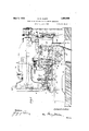
- Fig. l is a side elevation of the machine.
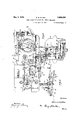
- Fig. 2 is a horizontal section through the bracket-arm standard of the machine, showing the sewing machine bed and associated mechanism in plan.
- Fig. 3 is a side elevation of the work-clamp of the machine.
- Fig. 4 is a disassembled perspective view of certain elements of the work-clamp.
- Fig. 5 is a trans verse vertical section through the machine bed, looking toward the bracket-arm standard, and
- Fig. 6 is a transverse vertical section through. the work-clamp, taken on the line 66, Fig. 2.
- the sewing machine illustrated herein is constructed substantially in accordance with the disclosure of the application of Edward E. Allen, Serial No. 400,767,1iled Oct. 19, 1929.
- the machine is constructed with a bed 1, from whichrises the standard 2 of the bracket-arm 3 terminating in the head 4.
- the stitch-forming mechanism comprises the reciprocating and laterally vibrating needle 5 andcooperating shuttle 6. which are operated as usual by the main-shaft 7 to make the usual zigzag buttonhole overseam commonly used in so-called straight buttonholes.
- the period of operation of the stitch-forming mechanism is controlled by the usual stop-motion device including the tilting stopmotion lever 8, fulcrmned on the trunnionscrews 9, and carrying the upwardly springpress'ed stop-plunger 10 adapted to enter a notch in the stop-cam 11 running with the main-shaft T.
- the stop-motion lever 8 is tilted to running or dotted-line position, Fig. 1, by a down-pull on the starting rod 12connected at 13 to an arm 14 rigid with andextending forwardly from the stop-motion lever 8.
- the rod 12 is released to stop the stitcheforming mechanism by the action of a tripping point 15 on theusual feed-wheel 16 which runs with. the stitch-forming mechanism.
- the tripping point 15 engages and swings a lever 17 which, inturn', trips the latch 18, Fig. 5, from engagement with the block 19 on theloperating lever '20, thus allowing the rod 12 and stop-motion lever 8 to return from running or dotted line position, Figs. 1 and '5, to full line or stopping position.
- the work isheld in a work-clamp which is moved longitudinally and laterally over the bed 1 by the usual connections with the feedwheel 16, to place the stitches around the buttonhole.
- the work clamp comprises the usual lower work-supporting plate 21 and upper clamping foot 22 which, unlike the construction disclosed in said Allen copending application, is not mounted directly upon the main upper clamp-ljever 23, but is carried instead by a supplemental lever 24 disposed beneath the main upper clamp-lever 23; the levers 23 and 24- b-eing independently fulcrumed preferably upon the same fulcrum pin 25 which is fixed by the screw 26, Fig. 6, in the ears 27 rising from a plate 28 screwed to the lower clamp-plate 21.
- the main upper clamp-lever 23 has fixed to it a downwardly and forwardly extending block 29 apertured at 30 to rock upon the fulcrum pin 25 between the supporting ears27, while the supplemental upper clamp-lever 24 has fixed to it the spaced ears 31 which are apertured to receive and rock upon the fulcrum-pin 25 at the outer sides of the supporting ears 27.
- a stud-screw 32, Fig. 3 fixed to the supplemental upper clamp-lever 24 rises through a clearance aperture 33 in the main upper clamp-lever 23 and has interposed between its head and the main clamp-lever 23 a relatively weak compression spring 34 which tends to maintain the lever 24 in contact with or parallel to the main lever 23, as shown in full lines in Fig. 3.
- the tail 23 of the main upper clamp-lever 23 extends rearwardly under a roller-stud 35 carried by the vertically disposed slide-bar 36, Fig. 5, formed in its upper end with a slot 37 entered by a screw 38 threaded into the clamp-lifting rock-arm 39 fulcrumed to turn upon and relative to the usual stop-motionoperated rock-shaft 40 mounted horizontally at the side of the standard 2 and common to machines of the straight buttonhole sewing engaging under the screw 38, operatively couples the slide-bar 36 to the rock-arm 39 for operation by the latter.
- the screw-pin 44 constituting the lower end of the slidebar 36, is guided in the stationary arm fixed to the bed 1.
- the rock-arm 39 is connected by the chain 46 to the ball crank-pin 47 on-the gear 48 fixed to the shaft 49 of a mechanical machine-operator fully disclosed in the said Allen copending application.
- the rock-lever 20, Fig. 5 is also connected to the ball crank-pin 47 by means of the link 50.
- a vertical post 51 which passes through clearance apertures 52, 53 in the respective upper clamp-levers 24, 23, and is surrounded by a comparatively strong spring 54 which presses downwardly upon the clamp-lever 23 and forces the clamp-foot 22 into clamping engagement with the work.
- a clownpull on the chain 46 therefore, forces the roller stud 35 downwardly upon the tail 23 of the main upper clamp-lever 23 and raises the .front end of the clamp-lever 23 against the pressure of the spring 54 and opens the workclamp.
- the spring 54 closes the work clamp.
- the shaft 49 carrying the ball crank-pin 47 is journaled in the frame 55 of the automatic machine operator which is stationed on the power-bench 56, alongside the sewing machine. There is also journaled in the frame 55 a driving shaft 57 carrying a pinion 58 of one-half the size of and meshing with the gear 48.- The ball-crank pin 47 is thus given a semi-rotational impulse with the shaft 49 for each complete rotation of the driving shaft 57.
- the shaft 57 is connected through a manually controlled one-rotation clutch-device including the usual clutch-controlling clamp.
- the gate 59 which is fulcrumed 0n the vertical stud-pin 59" may be swung inwardly about the pin 59 by a connection with the finger starting lever'60 to initiate one revolution of the shaft 57 to start the sewing machlne.
- This initial revolution of the shaft 57 carries the ball crank-pin 47 from its lowest position, Fig. 5, to its highest position (not shown).
- This movement of the crank-pin 47 relieves the pull on the chain 46 and allows the spring 54 to close the work- It also acts through the link 50 and lever 20 to pull down on the rod 12 and start the stitch-forming mechanism.
- the action of the stop-motion device in arresting the stitch-forming mechanism, imparts the usual rocking impulse to the shaft 40 to which is fixed an arm 61 having a bar-connection 62 for again shifting the gate 59 to initiate a second revolution of the driving shaft 57 which causes the ball crank-pin 47 to move from its highest position back to its lowest position, Fig. 5, and open the work-clamp.
- the connection of the gate59 with the finger starting lever includes the bell crank-lever 63 and the wire link 64.
- the clamp-foot 22 For certain classes of work it is desirable to use the rectangular opening 22 in the clamp-foot 22 as a sight or guide to the accurate positioning of the work in the workclamp, and the clamp-foot best serves as an accurate guide when in lowered position.
- the present improvement permits the clamp-foot to be pulled downwardly upon the work to serve as a sight in locating the work before the machine is started and while the main clamp-lever 23 is in clamp-opening posit-ion, Fig. 3.
- a work-clamp for sewing machines comprising a lower clamp-member, main and supplemental clamp-levers carried by said lower clamp-member, a clamp-toot carried by said supplemental clamp-lever, automatic means for operating said main clamp-lever, and manually operated means for moving said supplemental clamp-lever toward the lower clamp-member, and a recovery spring for lifting said supplemental clamp-lever.
- a work-clamp for sewing machines comprising a lower clamp-member, main and supplemental clamp-levers carried by said lower clamp-member, a clamp-toot carried by said supplemental clamp-lever, automatic means for operating said main clamp-lever, and a pull-chain and recovery spring connected to said supplemental clamp-lever.
- a sewing machine work-clamp comprising a lower work-supporting plate, a main upper clamp-lever fulcrumed on said plate, a supplemental upper clamp-lever tulcrumed for movement independently of said main upper clamp-lever, manually operated means for moving said supplemental clamp-lever toward the work-supporting plate independently of said main clamp-lever and while the latter is in clamp-opening position and a recovery spring for lifting said supplemental clamp-lever.
- a work-clamp having a lower work-supporting plate, an upper clamp-foot, an automatically operated main clamp-closing lever, a supplemental clamplever carrying said clamp-foot, and manually operated means connected to said supplemental clamp-lever to lower said clamp-toot, said main lever being arranged to press directly upon said supplemental lever in applying clamping pressure to said clamp-foot.
- a sewing machine work-clamp comprising, a lower clamp-member, main and supplemental clamp-levers carried by said lower clamp-member, a clamp-foot carried by said supplemental clamp-lever, a relatively strong clamp-closing spring acting upon said main clamp-lever, a relatively weak recovery spring acting upon said supplemental clamplever, automatic means for operating said
Landscapes
- Engineering & Computer Science (AREA)
- Textile Engineering (AREA)
- Sewing Machines And Sewing (AREA)
Description
May3, 1932. E. B. ALLEN WQRK CLAMP MECHANISM FOR SEWING MACHINES Filed April 4, 19 30 3 Sheets-Sheet l Jwumtoz Edward bill/32a y 1932- E. B. ALLEN 1,856,900
WORK CLAMP MECHANISM FOR SEWING MACHINES Filed April 1950 s Sheets-Sheat 2 E. B. ALLEN ,9
WORK CLAMP MECHANISM FOR SEWING MACHINES- 3 Sheets-Sheet 3 May 3, 1932.
Filed April 4, 1930 3 & WII IIIII ll Edward 15. Allen Patented May 3, 1932 UNITED STATES PATENT OFFICE EDWARD B. ALLEN, F NEWTOWN, CONNECTICUT, ASSIGNOR TO THE SINGER .MANU- FAGTURIN-G- COMPANY, OF ELIZABETH, NEW JERSEY, A CORPORATION OF NEW JERSEY WORK-CLAMP MECHANISM FOR SEWING MACHINES Application filed April 4, 1930. Serial No. 441,496.
The present invention relates to sewing machines and is herein shown as embodied in a buttonhole sewing machine of the full-automatic type, i. e., a machine which, when started, will perform all of its operations automatically in proper sequence and then come to rest. 7 v
The invention has for an object to improve the construction and mode of operation of,
0 sewing machines of the group-stitching type having a work-clamp, and particularly to provide an improved construction of workclamp mechanism for such machines.
The invention consists in the devices, combinations, and arrangements of parts hereinafter described and claimed.
The several features of the invention and the advantages attained thereby will be readily understood by those skilled in the art from the following description taken in connection with the accompanying drawings which illustrate the several features of the invention as embodied in a buttonhole sewing machine. Fig. l is a side elevation of the machine. Fig. 2 is a horizontal section through the bracket-arm standard of the machine, showing the sewing machine bed and associated mechanism in plan. Fig. 3 is a side elevation of the work-clamp of the machine. Fig. 4 is a disassembled perspective view of certain elements of the work-clamp. Fig. 5 is a trans verse vertical section through the machine bed, looking toward the bracket-arm standard, and Fig. 6 is a transverse vertical section through. the work-clamp, taken on the line 66, Fig. 2.
The sewing machine illustrated herein is constructed substantially in accordance with the disclosure of the application of Edward E. Allen, Serial No. 400,767,1iled Oct. 19, 1929. The machine is constructed with a bed 1, from whichrises the standard 2 of the bracket-arm 3 terminating in the head 4. The stitch-forming mechanism comprises the reciprocating and laterally vibrating needle 5 andcooperating shuttle 6. which are operated as usual by the main-shaft 7 to make the usual zigzag buttonhole overseam commonly used in so-called straight buttonholes.
The period of operation of the stitch-forming mechanism is controlled by the usual stop-motion device including the tilting stopmotion lever 8, fulcrmned on the trunnionscrews 9, and carrying the upwardly springpress'ed stop-plunger 10 adapted to enter a notch in the stop-cam 11 running with the main-shaft T. The stop-motion lever 8 is tilted to running or dotted-line position, Fig. 1, by a down-pull on the starting rod 12connected at 13 to an arm 14 rigid with andextending forwardly from the stop-motion lever 8. The rod 12 is released to stop the stitcheforming mechanism by the action of a tripping point 15 on theusual feed-wheel 16 which runs with. the stitch-forming mechanism. When the stitching operation is completed, the tripping point 15 engages and swings a lever 17 which, inturn', trips the latch 18, Fig. 5, from engagement with the block 19 on theloperating lever '20, thus allowing the rod 12 and stop-motion lever 8 to return from running or dotted line position, Figs. 1 and '5, to full line or stopping position.
The work isheld in a work-clamp which is moved longitudinally and laterally over the bed 1 by the usual connections with the feedwheel 16, to place the stitches around the buttonhole. The work clamp comprises the usual lower work-supporting plate 21 and upper clamping foot 22 which, unlike the construction disclosed in said Allen copending application, is not mounted directly upon the main upper clamp-ljever 23, but is carried instead by a supplemental lever 24 disposed beneath the main upper clamp-lever 23; the levers 23 and 24- b-eing independently fulcrumed preferably upon the same fulcrum pin 25 which is fixed by the screw 26, Fig. 6, in the ears 27 rising from a plate 28 screwed to the lower clamp-plate 21. Referring to Figs. 4 and 6, it will beseen thatthe main upper clamp-lever 23 has fixed to it a downwardly and forwardly extending block 29 apertured at 30 to rock upon the fulcrum pin 25 between the supporting ears27, while the supplemental upper clamp-lever 24 has fixed to it the spaced ears 31 which are apertured to receive and rock upon the fulcrum-pin 25 at the outer sides of the supporting ears 27. A stud-screw 32, Fig. 3, fixed to the supplemental upper clamp-lever 24 rises through a clearance aperture 33 in the main upper clamp-lever 23 and has interposed between its head and the main clamp-lever 23 a relatively weak compression spring 34 which tends to maintain the lever 24 in contact with or parallel to the main lever 23, as shown in full lines in Fig. 3.
The tail 23 of the main upper clamp-lever 23 extends rearwardly under a roller-stud 35 carried by the vertically disposed slide-bar 36, Fig. 5, formed in its upper end with a slot 37 entered by a screw 38 threaded into the clamp-lifting rock-arm 39 fulcrumed to turn upon and relative to the usual stop-motionoperated rock-shaft 40 mounted horizontally at the side of the standard 2 and common to machines of the straight buttonhole sewing engaging under the screw 38, operatively couples the slide-bar 36 to the rock-arm 39 for operation by the latter. The screw-pin 44, constituting the lower end of the slidebar 36, is guided in the stationary arm fixed to the bed 1. The rock-arm 39 is connected by the chain 46 to the ball crank-pin 47 on-the gear 48 fixed to the shaft 49 of a mechanical machine-operator fully disclosed in the said Allen copending application. The rock-lever 20, Fig. 5 is also connected to the ball crank-pin 47 by means of the link 50.
Rising from the lower clamp-member 21 is a vertical post 51 which passes through clearance apertures 52, 53 in the respective upper clamp- levers 24, 23, and is surrounded by a comparatively strong spring 54 which presses downwardly upon the clamp-lever 23 and forces the clamp-foot 22 into clamping engagement with the work. A clownpull on the chain 46, therefore, forces the roller stud 35 downwardly upon the tail 23 of the main upper clamp-lever 23 and raises the .front end of the clamp-lever 23 against the pressure of the spring 54 and opens the workclamp. When the down-pull on the chain 46 is relieved, the spring 54 closes the work clamp.
The shaft 49 carrying the ball crank-pin 47 is journaled in the frame 55 of the automatic machine operator which is stationed on the power-bench 56, alongside the sewing machine. There is also journaled in the frame 55 a driving shaft 57 carrying a pinion 58 of one-half the size of and meshing with the gear 48.- The ball-crank pin 47 is thus given a semi-rotational impulse with the shaft 49 for each complete rotation of the driving shaft 57. The shaft 57 is connected through a manually controlled one-rotation clutch-device including the usual clutch-controlling clamp.
fice for the purposes of the present disclosure to explain that the gate 59, which is fulcrumed 0n the vertical stud-pin 59", may be swung inwardly about the pin 59 by a connection with the finger starting lever'60 to initiate one revolution of the shaft 57 to start the sewing machlne. This initial revolution of the shaft 57 carries the ball crank-pin 47 from its lowest position, Fig. 5, to its highest position (not shown). This movement of the crank-pin 47 relieves the pull on the chain 46 and allows the spring 54 to close the work- Italso acts through the link 50 and lever 20 to pull down on the rod 12 and start the stitch-forming mechanism. Y
\Vhen the sewing is completed, the action of the stop-motion device, in arresting the stitch-forming mechanism, imparts the usual rocking impulse to the shaft 40 to which is fixed an arm 61 having a bar-connection 62 for again shifting the gate 59 to initiate a second revolution of the driving shaft 57 which causes the ball crank-pin 47 to move from its highest position back to its lowest position, Fig. 5, and open the work-clamp. The connection of the gate59 with the finger starting lever includes the bell crank-lever 63 and the wire link 64. v
The mechanism so far described is, with the exception of the supplemental upper clamp-lever 24, constructed substantially in accordance with the disclosure of said Allen copending application. In the machine of said copenfding application the clamp-foot 22 is automatically raised when the machine comes to rest and is automatically lowered when the machine is started. It requires no effort on the part of the operator to manipulate the work-clamp against the relatively considerable pressure of the clamp-closing spring 54.
For certain classes of work it is desirable to use the rectangular opening 22 in the clamp-foot 22 as a sight or guide to the accurate positioning of the work in the workclamp, and the clamp-foot best serves as an accurate guide when in lowered position. The present improvement permits the clamp-foot to be pulled downwardly upon the work to serve as a sight in locating the work before the machine is started and while the main clamp-lever 23 is in clamp-opening posit-ion, Fig. 3. There is fixed to the supplemental clamp-lever 24 a lateral arm 65 to which is connected a treadle-chain 66 by means of which the supplemental clamp-lever 24 may be swung from full line to dotted line position, Fig. 3, to lower the clamp-foot 22 into sighting or gaging position before the operator presses upon the starting button 60. This preliminary movement of the supplemental lever 24: and foot 22 requires little ettort on the part of the operator as it is resisted only by the weak spring 34. As soon as the machine is started, the pressure of the heavy spring 54 is brought to bear upon the clamp-foot 22, as will be readily understood.
Having thus set forth the nature of the invention, what I claim herein is:
1. A work-clamp for sewing machines comprising a lower clamp-member, main and supplemental clamp-levers carried by said lower clamp-member, a clamp-toot carried by said supplemental clamp-lever, automatic means for operating said main clamp-lever, and manually operated means for moving said supplemental clamp-lever toward the lower clamp-member, and a recovery spring for lifting said supplemental clamp-lever.
2. A work-clamp for sewing machines comprising a lower clamp-member, main and supplemental clamp-levers carried by said lower clamp-member, a clamp-toot carried by said supplemental clamp-lever, automatic means for operating said main clamp-lever, and a pull-chain and recovery spring connected to said supplemental clamp-lever.
3. A sewing machine work-clamp comprising a lower work-supporting plate, a main upper clamp-lever fulcrumed on said plate, a supplemental upper clamp-lever tulcrumed for movement independently of said main upper clamp-lever, manually operated means for moving said supplemental clamp-lever toward the work-supporting plate independently of said main clamp-lever and while the latter is in clamp-opening position and a recovery spring for lifting said supplemental clamp-lever.
4. In a sewing machine, stitch-forming mechanism, a stop-motion device, a workclamp, a clamp-closing spring, automatic means for opening the work-clamp against the force of said clamp-closing spring, and manually operated means independent of said spring for closing the work-clamp before the machine is started.
5. In a sewing machine, a work-clamp having a lower work-supporting plate, an upper clamp-foot, an automatically operated main clamp-closing lever, a supplemental clamplever carrying said clamp-foot, and manually operated means connected to said supplemental clamp-lever to lower said clamp-toot, said main lever being arranged to press directly upon said supplemental lever in applying clamping pressure to said clamp-foot.
6. A sewing machine work-clamp comprising, a lower clamp-member, main and supplemental clamp-levers carried by said lower clamp-member, a clamp-foot carried by said supplemental clamp-lever, a relatively strong clamp-closing spring acting upon said main clamp-lever, a relatively weak recovery spring acting upon said supplemental clamplever, automatic means for operating said
Priority Applications (1)
| Application Number | Priority Date | Filing Date | Title |
|---|---|---|---|
| US441496A US1856900A (en) | 1930-04-04 | 1930-04-04 | Work-clamp mechanism for sewing machines |
Applications Claiming Priority (2)
| Application Number | Priority Date | Filing Date | Title |
|---|---|---|---|
| US441496A US1856900A (en) | 1930-04-04 | 1930-04-04 | Work-clamp mechanism for sewing machines |
| GB1896930A GB352699A (en) | 1930-06-21 | 1930-06-21 | Work clamp mechanisms for sewing machines |
Publications (1)
| Publication Number | Publication Date |
|---|---|
| US1856900A true US1856900A (en) | 1932-05-03 |
Family
ID=26253712
Family Applications (1)
| Application Number | Title | Priority Date | Filing Date |
|---|---|---|---|
| US441496A Expired - Lifetime US1856900A (en) | 1930-04-04 | 1930-04-04 | Work-clamp mechanism for sewing machines |
Country Status (1)
| Country | Link |
|---|---|
| US (1) | US1856900A (en) |
-
1930
- 1930-04-04 US US441496A patent/US1856900A/en not_active Expired - Lifetime
Similar Documents
| Publication | Publication Date | Title |
|---|---|---|
| US1537155A (en) | Tacking and barring machine | |
| US1856900A (en) | Work-clamp mechanism for sewing machines | |
| US2043929A (en) | Button sewing machine | |
| US2560186A (en) | Label feeding and holding means for sewing machines | |
| US2251676A (en) | Thread wiper for sewing machines | |
| US1234258A (en) | Thread cutting and holding device for sewing-machines. | |
| US2188228A (en) | Blind stitch sewing machine | |
| US1542865A (en) | Sewing machine | |
| US2645192A (en) | Automatic button-clamp lifting means | |
| US2003461A (en) | Sewing machine | |
| US1352514A (en) | Sewing-machine | |
| US2116889A (en) | Sewing machine safety device | |
| US2075759A (en) | Stop-motion device for sewing machines | |
| US1688057A (en) | Thread-measuring mechanism for sewing machines | |
| US1404727A (en) | Thread cutting and nipping mechanism for sewing machines | |
| US1394075A (en) | Sewing-machine | |
| US1255970A (en) | Sewing-machine. | |
| US2210638A (en) | Thread and cord trimmer for buttonhole sewing machines | |
| US822551A (en) | Button-sewing machine. | |
| US2165016A (en) | Tension-releaser for sewing machines | |
| US1646946A (en) | Cord-handling mechanism for buttonhole-sewing machines | |
| US1865140A (en) | Buttonhole sewing machine | |
| US2020779A (en) | Buttonhole sewing machine | |
| US2063845A (en) | Attachment for sewing machines | |
| US2352708A (en) | Shoe sewing machine and driving and stopping mechanism therefor |