US1856897A - Stock line recorder - Google Patents
Stock line recorder Download PDFInfo
- Publication number
- US1856897A US1856897A US217448A US21744827A US1856897A US 1856897 A US1856897 A US 1856897A US 217448 A US217448 A US 217448A US 21744827 A US21744827 A US 21744827A US 1856897 A US1856897 A US 1856897A
- Authority
- US
- United States
- Prior art keywords
- motor
- bell
- cable
- test
- limit switch
- Prior art date
- Legal status (The legal status is an assumption and is not a legal conclusion. Google has not performed a legal analysis and makes no representation as to the accuracy of the status listed.)
- Expired - Lifetime
Links
- 238000004804 winding Methods 0.000 description 39
- 239000004020 conductor Substances 0.000 description 23
- 230000007246 mechanism Effects 0.000 description 21
- 230000009471 action Effects 0.000 description 5
- 230000008859 change Effects 0.000 description 4
- 241001481828 Glyptocephalus cynoglossus Species 0.000 description 2
- 241001422033 Thestylus Species 0.000 description 2
- 230000004048 modification Effects 0.000 description 2
- 238000012986 modification Methods 0.000 description 2
- 101100167280 Caenorhabditis elegans cin-4 gene Proteins 0.000 description 1
- 230000008901 benefit Effects 0.000 description 1
- 150000001875 compounds Chemical class 0.000 description 1
- 230000008021 deposition Effects 0.000 description 1
- 238000010586 diagram Methods 0.000 description 1
- 229940084430 four-way Drugs 0.000 description 1
- 239000000463 material Substances 0.000 description 1
- 238000000034 method Methods 0.000 description 1
- 230000009467 reduction Effects 0.000 description 1
- 230000004044 response Effects 0.000 description 1
- 230000000284 resting effect Effects 0.000 description 1
Images
Classifications
-
- G—PHYSICS
- G01—MEASURING; TESTING
- G01F—MEASURING VOLUME, VOLUME FLOW, MASS FLOW OR LIQUID LEVEL; METERING BY VOLUME
- G01F23/00—Indicating or measuring liquid level or level of fluent solid material, e.g. indicating in terms of volume or indicating by means of an alarm
- G01F23/0023—Indicating or measuring liquid level or level of fluent solid material, e.g. indicating in terms of volume or indicating by means of an alarm with a probe suspended by a wire or thread
Definitions
- a further object is to provide a means for continuously indicating the level of the charge within .a blast furnace, which means will have improved accuracy over prior devices and which will at once indicate a rise in the charge even though said rise is caused by conditions other than the deposition of added material into the blast furnace.
- a further object is to provide a level indicator including a weighted test member hav- Q ing a cable attached thereto vfor operating same, which level indicator has the advantage that said cable will be maintained taut under all conditions.
- a further object is to provide an improved method for continuously indicating the level of thecontents within a blast furnace or the like.
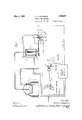
- FIG. l is a diagrammatic view illustrating one embodiment of the present invention.
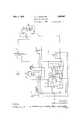
- Figure 2 is a schematic view illustrating he electrical connections which may beutilized in connection with the apparatus shown in 1)figure l;
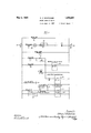
- Figure 3 is a wiring diagram showing the electric connections of Figure 2 in more com- Y pact form and omitting the showing of deof certain of the instrumentalities shown in Figure 2.
- the present invention contemplates the use of a weighted test or try rod which may have a movement of reciprocation in a vertical direction within a blast furnace or otherre- Y ceptacle.
- a plurality of test rodsr may be provided, but only one test rod and the control means therefor have been illustrated'in the drawings, inasmuch as the illustration of one test rod and its control means will be suflicient in explainingv the invention.
- Said test rod is preferably held in a vertical position at all times, and may be lifted by means of aV flexible connector or cable, which in turn is controlled by a Winding drum or equivalent means.
- Said winding drum or equivalent means is'driven through suitable gear reductions or' other power transmitting means from an electric motor, which may be shunt or compound wound.
- said motor may be provided with a brake Wheel, which may be controlled by a brake biased to braking position.
- Electrical control means may be provided for releasing said brake.
- a recording meter may be provided drivenfrom the shaft of said winding drum, said meter being operated by any well known means to produce the result that the amount of deflection of the stylus of said meter is proportional to the amount of rotation of the winding drum. Means are contemplated for opening a limit switch after a predetermined rotation of said winding drum.
- a typical cycle of operation may be stated as follows: Operation of a start button or equivalent means connects the driving motor of said winding drum to a source of electric current, a relatively large amount of resistance being provided in series with the motor. The brake above referred to is released by this same operation.
- the motor is connected across the source of electric current in such a way that said motor develops torque tending to cause the winding drum to hoist the test rod.
- the resistance in series with said motor is of such value vthat insutlicient current is applied to said motor to develop a torque of sufficient value to cause the winding drum to'hoist, so that the net result is that the test rod descendsand causes the winding drum to overcome the opposing torque of the motor.
- the test rod descends until it rests upon the charge, and the motor continues to develop a torque tending to raise the test rod, the result being that the cable connecting the test rod to the winding drum is kept taut.
- Means are provided for connecting the control means of the charging bell of the blast furnace with the o erating means for the test rod, whereby before the charging bell of said blast furnace has opened, the testV rod is hauled up.
- lnterloclring means which will occur to those skilled in the art may be provided for accomplishing this result.
- Operation of a push button or equivalent means establishates thek operation of instrumentalities short-circuiting a portion or all of the resistance in series with the motor connected to the winding drum. This permits the motor to obtain more current, causing the motor to develop sufficient torque to cause the winding drum to raise the test rod to the top of the furnace. l/Vhen the test rod reaches the top of the furnace, a limit switch is operated, causing.
- a blast furnace l is indicated having the charging bell 2, which may be of any usual type.
- Said charging bell 2 may be operated by any preferred mechanism, suitable mechanism for the rpurpose being diagrammatically indicated in Figure l and being indicated by the numeral 2o.
- Mounted within the blast furnace l is the test rod 3, which test rod is guided for straight line movement within the sleeve 3a, where-b y said test rodalways occupies a vertical position.
- V Sad test rod is controlled by means of the cable or flexible connector 4 disposed upon the sheaves Said cable 4 is connected to the winding drum 6, which may be grooved if preferred.
- An electric motor 7 is provided for turning the drum 6, a pinion 8 being indicated upon the motor shaft adapted to engage with the gear Sa coaxially mounted with the winding drum 6.
- the shaft of the electric motor 7 is provided with the bralre wheel 9, which bri-.lie wheel is controlled by the brake slices lll-l0, which shoes are normally biased to braking position.
- a brake coil ll is provided, which when energized is adapted to hold the brake shoes lO-lO out of braking relations iip with the brake wheel 9.
- Driven synchronously with the winding drum 6 is the flexible shaft 12 adapted to drive the worm 13. Said worm 13 engages the worm wheel llt, which worm wheel is adapted to drive the recording meter l5.
- the worm wheel lll is adapted, through connections not shown, to control the lever 16 for operating the normally7 closed limit switch 17a, which is one of a plurality of limit switches to be referred to herelnafter.
- rlhe instrumentalities above referred to are controlled electrically by means which for purposes of description may be referred to as the stock line recorder controller, which controller is indicated in Figures 1 and 2 by the numeral 19.
- Figures 2 and 3 show the electr'cal connections of the mechanism shown in Figure 1.
- the numerals 18-18 indicate the mo sides of an electric circuit, w lich circuit may if be controlled bythe blades l8c-l8c of a double pole switch.
- rEhe electric motor 7 comprises the armature 20, the series field winding ⁇ 21 and the shunt field winding ⁇ 21a, said armature and series field winding being connected in series with the resistance 26 across the conductors l8,l 8, lthrough the contactor 22, which contactor 22 is biased to open position. B 1idged across the resistance 26 is the contact-or 24, which contacter 24 s biased to open position.
- rlhe shuntV field winding 21a is connected across the conductors l6-16- Also connected across the cin4 cuit comprising the series field winding 2l, armature 20 and the resistance 26 is a circuit including the brake coil ll, which coutrols the brake shoes lO-lO cooperating with the brake wheel 9.
- Bridged across the conductors lS-lS is a circuit including the operating coil 29 of the contactor 22 and the normally closed limit switch l'a.
- rEhe limit switch 17a is so connected to the winding drum 6 that said limit switch 17a is cause-1l to open when the winding drum has reeled un sufficient cable l to hoist the test roc 3 to the top of the furnace l.
- the limit switcl 17a is biased to closed position, being caused to open only when the test rod 3 reaches the aforesaid position at the top of the furlla-CQ.
- Bridoed across the o )ei-ating coil 29 ZD D is a circuit including the operating coil 27 of the contactor 24 and the push button or equivalent switch 31.
- the auxiliary switch 33 which is mechanically actuated by the contacter and is open when contactor 24 is open.
- Bridged across the limit switch 17a is a circuit including the contacter 35 and the normally open limitswitch 175.
- the limit switch 175 is located on the operating mechanism of the charging bell 2 in such a manner that it is closed when said charging bell 2 is closed. Said limit switch 175 is biased to open position and is closed only when the charging bell 2 is closed.
- Bridged across the conductors 13-18 is a circuit including the coil 36 of the contacter 35, the normally closed auxiliary switch 33a., and the normally open limit switch 170.
- the normally closed auxiliary switch 33a is closed when contacter 24 is open and is open when contacter 24 is closed.
- the limit switch 170 is so connected to the operating mechanism 2a of ⁇ the charging bell 2 that it will bc closed when said charging bell 2 is completely open. Said limit switch l'cis biased to open position and is closed only when the charging bell 2 is open.
- Shunted around the limit switch 170 is a circuit including the auxiliary switch 37, which is caused to function by the contacter 35 and is open when said contacter 35 is open.
- the vdetails of the control mechanism 30 form no part of the present invention, and suitable control mechanism will readily occur to those skilled in the art.
- a suitable control mechanism 30 will be briefly referred to hereinbelow.
- the function of the circuit immediately above referred to is to cause the charging bell 2 to open upon the occurrence'of a predetermined event, such for example as the completion of the hoisting of the test-rod 3.
- Bridged across the conductors 18-18 is the limit switch 17d and the charging bell control mechanism 30.
- rllhe limit switch 17d is located adjacent to the operating mechanism 2a oit the charging bell 2 at the same level at which the limit switch 170 is located.
- Limit switch 17d is biased to open position and operates simultaneously(with and in a manner similar to limit switch 17o.
- Bridged across the conductors 18--13 is a circuit, including the bell control 30the normally closed auxiliary witch 35a (closed when contactor 35 is open), and the normally closed auxiliary 22a (closed when contactor 22 is open).
- the bell operating mechanism comprises a cylinder 2a which may be operated by compressed yair so as to cause the lowering and hoisting of the bell 2.
- the cylinder 2a When air is admitted to the top side of the piston 25,'the cylinder 2a is hoisted, causing lowering ot the bell 2, and when air is admitted to the bottom side of the piston 25, the cylinder is lowered, thereby causing hoisting or closing ⁇ of the bell 2.
- the compressed air may be taken from any convenient source, such for example as the turbo blower supplying air to the blast furnace.
- the pipe 2c is connected to such a source.
- Compressed air is admitted to the top or bottom of the piston 25 by means of a fourway valve 2d, which valve is operated byY a motor indicated by the character m, which consists of an armature 300 and two series field windings 30d and 30e.
- the motor 30m is shown as being in driving relationship with a screw 30;c having a traveling nut 30g adapted to engage selectively the two limit switches 30a and 305.
- Said field windings 30d and 30e are adapted to be used alternatively and are oppositely wound, wherebythe use of one of said lield windings 30:! or 30e causes motor rotation in one direction,
- circuit including the normally open limit switch 17d, the normally closed limit switch 30a, the series lield winding 30d and the armature 30o of the motor 30m, which operates the valve 2d.
- the limit switch 30a is operated by the valve 2d when the bell has traveled a predetermined distance in the direction opposite to that which causes th actuation of the limit switch 305.
- a typical cycle of operation is as follows: F or the purpose of this description a cycle will be assumed as beginning with the test rod 3 resting upon the charge in the furnace or receptacle. Under this condition the contactor 22 will have been closed by meansof a circuit completed through the coil 29 01"' contact-or' 22. This circuit comprises the coil 29,
- ⁇ anisni 2a is .in a position to cause-the bell '2 to be closed. It the time this :circuit was completed, contacter 22 was closed, which completed a circuit from one conductor 18 through the series field winding 21, through the armature 20, through 'the resistance 26 and throuch said ⁇ contactor 22 to the other conductor'iS.
- the result of the closing of the last .mentioned circuit is that the motor 7 is placed across the conductors 18-1-8 in series with the resistance 2G.
- Said resistance 26 . is of suicient value to cause the motor 7 to develop- :torque sufficient to reelup slack in the cable 4, but the torque is not suliiciently great to cause the winding drum 6 to lift the test rod 3.
- the test rod 3 ill rise, the cable 4 will be reeled up and a corresponding movement of the drum 6 will be indicated through the ilexible shaft 12, worm 13, worm wheel 14 and recording meter 15. Should the burden fall, the test rod 3 will descend, causing 'the cable 4to be reeled olf the winning' drum 6, giving a corresponding' indication on the recording meter 15.
- the push button switch or equiyalent switch 31 is operated, thereby completing circuit from one conductor 18 through the coil 27 of the contactor 24, through the push button switch 31, through the normally closed limit switch 17a, to the other conductor 18. This results in the closure of the contactor 24.
- Closure of contactor 24 closes the auxiliary switch 33, said auxiliary switch 33 being mechanically connected to and operated by contactor 24, which results in bridging the push button switch 31, thereby forming a sustaiirv ing circuit around said push button switch 31 after pressure is released from said push button switch 31.
- Closure ⁇ ot contactor 24 opens the normally closed auxiliary switch 33a thereon (closed when contactor 24 is open), which opens the circuit through coil 36 of contacter 35, thereby causing contacter 35 to open. This does not interrupt circuit through coil 24 of contacter 22 because of the bridging' circuit through the limit switch 17a.
- the limit switch17a is closed at all times, except when the test rod 3 is hoisted tok the top of the furnace.
- the normally closed limit switch 17o is opened, to thereby open circuit from connes/onor ductor 18 through coil 29 of contactor 22 'and coil 27 ⁇ of contactor 24, thereby causing said two contactors 22 and 24 to open.
- the opening of contactor 24 causes the closing of normally closed switch 33a thereon, which closure results in no further action at this time.
- the charging bell 2 is caused to open.
- the normally open limit switch 17 c (which is operated by the bell operating mechanism 2a) is closed, thereby'completing a circuit across the conductors 18-18 including' the coil 36 of contactor 35, the normally closed auxiliary switch ⁇ 33a and limit switch 170.
- Completion of this circuit causes contacter 35 to close.
- Closure of contactor 35 closes the auxiliary switch 37 thereon, said switch 37 being mechanically operated by contactor 35 and closed when contacter 35 isv closed.
- Closure of the auxiliary switch 37 forms a bridging circuit around the limit switch 17 c. Cl-osure of the contacter 35 causes no further action at this time.
- the limit switch 17d is closed, said limit switch 17 cl, as above described, being positioned to be operated by the cylinder 2a ot the charging bell 2 and caused to function when said bell 2 is in the full open position.
- Closure of said limit switch 17a7 completes a circuit across the conductors 18-18 through said limit switch 17d and the charging bell control mechanism 30.
- the circuit through the bell control mechanism may be traced as follows: From the limit switch 17 d, the circuit continues through the limit switch 30a, the series field winding 30d and the armature 300 to the con- Lei-sass?V duct-or 18.
- Closure of contactor 22 completes a circuit across the conductors 18-18 including the brake coil 11, which causes the brake shoes 10-10 to release the brake wheel 9. Closure of saidcontactor 22 also completes a circuit across the conductors 18-18, including the series field winding 2l, the armature 20 of the motor 7 and the resistance 26. Completi-on of this last mentioned circuit causes the motor 7 to develop a torque tending to cause the winding drum 6 to reel up the cable a and hold the test rod 3 at the top of the furnace 1.
- the present invention provides a system which will give a continuous indication of the level of charge within a blast furnace or other receptacle, which will respond at once to changes in said level, and which will always maintain a taut cable, whereby to render it certain that a change of indication means a change in stock level and not merely a change in the tightness of the cable.
- a receptacle the level of the contents of which is to be indicated, a weighted test member adapted to rest for prolonged periods of time upon the top of said contents, an electric motor for raising said test member, a cable connected to said test member adapted to be wound up by said motor, means for limiting the pull of said motor upon said cable to a value sufcient to hold said cable taut without lifting said test member from said contents, a closure for said receptacle, operating means for said closure and means responsive to a raised position of said test member for controlling said closure operating means.
- a charging lbell operating means therefor, a test member adapted to rest upon the charge within said blast furnace, a cable connected to said test member, an electric motor for applying a tension to said cable, a control circuit for said motor, said control circuit including means adapted under predetermined conditions to cause said motor to eX- ert a torque suiiicient to keep said cable taut when said test member is upon said charge but insufficient to lift said testl member, said control circuit including means for 'increasing the torque of said motor, when it is desired to lift said test member from said charge, said bell operating means being responsive to a raised position of said test member.
- a blast furnace in combination, a charging bell thereof, operating means for said bell, a test member adapted to rest upon the charge within said blast furnace, a cable connected to said test member, an electric motor, control mea-ns for said motor adapted under predetermined conditions to limit the pull of said motor upon said cable to that suiiicient to hold same taut but insuiiicient to lift said test member, and means responsive to a raised position of said test member for modifying said bell operating means to cause the opening of said bell.
- a blast furnace in combination, a charging bell thereof, operating means for said bell, a test member adapted to rest upon the charge within said blast furnace, a cable connected to said test member, an electric motor, control means for said motor adapted under predetermined conditions to limit the pull of said motor upon said cable to that suiiicient to hold same taut but insuflicient combination, a weighted test member, a cable connected to said test member, an electric moto a lifted position of said testmember fer controlling said' bell operating means.
- a charging bell, operatingmeans for, said bell in combination, a test member for. indicating the level of the charge Within said furnace, a cable for1 raising saidltest member, a motor. for exerting pull upon said cable, brake means for. said ⁇ motor biased f to braking relationship With said motor when said ⁇ testmember isa-t a .pre1 determined position v out. of indicating relationship withl the charge Within saidfurnace, and means for releasing said b-ralremeans in response to the operation ,of saidbell operating means,
- a charging bell-thereof operating means for saidbell, a.v tesamember. 'for indicating the level of charge -Within saidfurnace, aY cable connected to said test member, amotor for exerting apull upQn Said cable,rcontrol means for said motor, said control means including means for governing .the torque of said motor to keep said cable taut Without raising said test member, meansfor increasing the torquel of said motor to raise said test member and meansresponsive to a raised position of said f test member for controlling said bell operatt ing ⁇ means.
- a charging bell-thereof operating means for said bell, attest member forindicating the level of charge
- a cable connected to said test member, an electric motor for ⁇ exerting a pull upon said cable, brake means for said motor biasedto braking relationship therewith,electric .control means l; forsaid motor, said electriccontrol. means4 exert a continuous pull upon said cable when Sei@ @Si @mbar is in level: indicating position, meansfor controlling said motor to liftL said test member out of level indicating position whenv saidA bell is about to open,l and means forV releasing said brake means when said bell has returned to closed position;
- a chargingL bell in combination, a chargingL bell thereof, operating means for said bell, test, member for indicating the level of charge
- a cable connected to said test member an electricV motor for exerting a pull upon said cable
- brake.. meansL for said motor biased to braking. relationship therewith
- electric control means for said motor said electric controlvr meansincluding means for causing said motor to eXert a.. continuouspull. upon saidA cablewhensaid test member is. inlevel indieating, position, means responsive to ⁇ vsaid' bell operating mea-ns for cent rollingv said motor toliftfsaidtest member out of level indicatingy positionbefore said bell can be opened, and 'means for releasing said brake.
- test member is inlevel indicating posities 11, In atblast. furnace, inv combination, atcharging bell, operatingmeans therefor, a test'inember,y adaptedto restupon the charge Within saidblast furnace, a cable connected to said test finember, an electric ⁇ motorv forapf. plying a tension .to vsaid cable, a controlA cir-.
- cuitfdr lsaidlmotor for causing saidmotorto eiert a torque-sufiicient to keep said cable taut'whensaidtest, member is uponlsaid charge bnty insuflicientto lift said ,test-member, said control circuit includingkmeans. for increasing the..torquew .of saidmotor vtowlift said test member from said charge and means responsive. to a-raised position of said test member fory controlling said belloperatingmeans.
- said controlnie'ans includingA meanrsfor limiting the .pullof said motor upon said cable to avalue suiicientto liold K- said cable. taut butinsufficient to lift said testmember.
- Lsaid lcontrol means also including means for modifyingsaid limiting. means whereby saidvlnetor maylli-ft said test ⁇ member.4
- control means for said motor connected to said cable, a brake for holding said test member in an uppermost position, means responsive to said bell for releasing said brake, control means for said motor, said control means including means for limiting the pull of said motor upon said cable to a value sufficient to hold said cable taut but insufficient to lift said test member, said control means also including means for modifying said limiting means whereby said motor may lift said test member, and connecting means between said bell and said control means for said motor for insuring a predetermined sequence of operation of said test member and said bell.
- a weighted test member adapted to rest for prolonged periods of time upon the top of said contents, an electric motor for raising said test member, a cable connected to said test member adapted to be wound up by said motor, means for limiting the energi- Zation of said motor to a value such that said motor will exert a pull upon said cable sufficient to hold said cable taut without lifting said test member from said contents, means for controlling said limiting means to cause said motor to raise said test member, a closure for said receptacle and operating means for said closure, said operating means being responsive to the position of said test member.
- a level indicator comprising a weighted test member, a cable connected thereto, an electric motor connected to said cable, and control means 'for said motor, said control means including limiting means for limiting the energization of said motor to a value whereby said motor will exert a pull upon said cable su'cient to hold said cable taut but insuiicient to raise said test member, whereby when said test member becomes raised or lowered through other means, said motor will rotate to take up or pay out cable, a closure :for said receptacle and operating means for said closure, said operating means being responsive to the position of said test member.
- a device for continuously indicating fluctuations in level in combination, a receptacle, the level or" the contents of which is to be indicated, a closure for said receptacle, operating means for said closure, a weighted test member, a cable connected thereto, an electric motor connected to said cable, control means for said motor, said control means including limiting means for limiting the pull of said motor upon said cable to a value such that said motor exerts, under predetermined conditions, a continuous pull upon said cable sufficient to hold said cable taut but insufiicient to raise said test member, whereby when said test member becomes raised or lowered through other means said motor Vwill rotate to take up a pay out cable and means responsive to a raised position of said test member for controlling said closure operating means.
Landscapes
- Physics & Mathematics (AREA)
- Fluid Mechanics (AREA)
- General Physics & Mathematics (AREA)
- Control Of Electric Motors In General (AREA)
Description
May 3, 1932. A. J. wHlTcoMB 1,855,897
' STOCK LINE RECORDER Filed Sept. 3. 192'? 3 Sheets-Sheet l May 3, 1932. A. J. wHlTcoMB `STOCK LINE RECORDER 'Filed Sept-3, 1927 3 SheebS-Shee'fl 2 NN\\ Nhgm VII! @MMG-M Filed Sept. 5, 1927 3 Sheets-Sheet SHUNT FIEL nel BELL 60A/m01.
Patented May 3, 1932 nuire Tp@ ,para
ries
BTHUR J. WHITCOll/IB, OF CHICAGO, ILLINOIS, ASSIGNOR 'IO FREYN ENGINEERING- COMPANY, CF CHICAGO, ILLINOISVA CORPORATION OF MAINE STOCK LINE RECORDER Application filed September 3, 1927. SerialNo. 217,448.
level of the charge within a blast furnace and has for one of its objects the provision of means for accomplishing this purpose which is well adapted to meet the needs of commercial service.
A further object is to provide a means for continuously indicating the level of the charge within .a blast furnace, which means will have improved accuracy over prior devices and which will at once indicate a rise in the charge even though said rise is caused by conditions other than the deposition of added material into the blast furnace.
A further object is to provide a level indicator including a weighted test member hav- Q ing a cable attached thereto vfor operating same, which level indicator has the advantage that said cable will be maintained taut under all conditions.
A further object is to provide an improved method for continuously indicating the level of thecontents within a blast furnace or the like.
Further objects will appear as the description proceeds.
Referring to the drawings- Figure l is a diagrammatic view illustrating one embodiment of the present invention;
Figure 2 is a schematic view illustrating he electrical connections which may beutilized in connection with the apparatus shown in 1)figure l; and
Figure 3 is a wiring diagram showing the electric connections of Figure 2 in more com- Y pact form and omitting the showing of deof certain of the instrumentalities shown in Figure 2.
detailed explanation of the present in- .cn may be prefaced by a short statement of the functions of the apparatus above l referred to.
The present invention contemplates the use of a weighted test or try rod which may have a movement of reciprocation in a vertical direction within a blast furnace or otherre- Y ceptacle. A plurality of test rodsrmay be provided, but only one test rod and the control means therefor have been illustrated'in the drawings, inasmuch as the illustration of one test rod and its control means will be suflicient in explainingv the invention. Said test rod is preferably held in a vertical position at all times, and may be lifted by means of aV flexible connector or cable, which in turn is controlled by a Winding drum or equivalent means. Said winding drum or equivalent meansis'driven through suitable gear reductions or' other power transmitting means from an electric motor, which may be shunt or compound wound. The shaftv of .Y
said motor may be provided with a brake Wheel, which may be controlled by a brake biased to braking position. Electrical control means may be provided for releasing said brake. A recording meter may be provided drivenfrom the shaft of said winding drum, said meter being operated by any well known means to produce the result that the amount of deflection of the stylus of said meter is proportional to the amount of rotation of the winding drum. Means are contemplated for opening a limit switch after a predetermined rotation of said winding drum. A typical cycle of operation may be stated as follows: Operation of a start button or equivalent means connects the driving motor of said winding drum to a source of electric current, a relatively large amount of resistance being provided in series with the motor. The brake above referred to is released by this same operation. The motor is connected across the source of electric current in such a way that said motor develops torque tending to cause the winding drum to hoist the test rod. However, the resistance in series with said motor is of such value vthat insutlicient current is applied to said motor to develop a torque of sufficient value to cause the winding drum to'hoist, so that the net result is that the test rod descendsand causes the winding drum to overcome the opposing torque of the motor. The test rod descends until it rests upon the charge, and the motor continues to develop a torque tending to raise the test rod, the result being that the cable connecting the test rod to the winding drum is kept taut. y Should the charge in the blast furnace rise at any time, the test rod will be raised, and automatically the winding drum will take up the slack in the cable. Should the charge fall, .the test rod will descend, causing the cable to be unreeled from the winding drum. Consequently, for each change of level of the charge within the blast furnace, corresponding movements are given to the winding drum, which produces a deflection of the stylus of the. recording meter in proportion to the amount of rotation vof the winding drum.
Means are provided for connecting the control means of the charging bell of the blast furnace with the o erating means for the test rod, whereby before the charging bell of said blast furnace has opened, the testV rod is hauled up. lnterloclring means which will occur to those skilled in the art may be provided for accomplishing this result. Operation of a push button or equivalent means inaugurates thek operation of instrumentalities short-circuiting a portion or all of the resistance in series with the motor connected to the winding drum. This permits the motor to obtain more current, causing the motor to develop sufficient torque to cause the winding drum to raise the test rod to the top of the furnace. l/Vhen the test rod reaches the top of the furnace, a limit switch is operated, causing. the operation of certain instrumentalities, to be referred to hereinafter, to disconnect the motor from the line and causing the brake to set, with the result that the test rod is held at the top of the furnace. As soon as the charging bell has completed its operation, said start button above referred to or equivalent instrumentalities may be operated (which instrumentalities may be interlocked with the bell cont-rol) causing the motor to be again connected acrossthe line in series with this resistance, thereby7 initiating` the cycle hereinabove described, causing the test rod to descend to the level of the charge and to resumeA a continuous indication of such level.
Referring more particularly to the drawings, a blast furnace l is indicated having the charging bell 2, which may be of any usual type. Said charging bell 2 may be operated by any preferred mechanism, suitable mechanism for the rpurpose being diagrammatically indicated in Figure l and being indicated by the numeral 2o. Mounted within the blast furnace l is the test rod 3, which test rod is guided for straight line movement within the sleeve 3a, where-b y said test rodalways occupies a vertical position.V Sad test rod is controlled by means of the cable or flexible connector 4 disposed upon the sheaves Said cable 4 is connected to the winding drum 6, which may be grooved if preferred. An electric motor 7 is provided for turning the drum 6, a pinion 8 being indicated upon the motor shaft adapted to engage with the gear Sa coaxially mounted with the winding drum 6. The shaft of the electric motor 7 is provided with the bralre wheel 9, which bri-.lie wheel is controlled by the brake slices lll-l0, which shoes are normally biased to braking position. A brake coil ll is provided, which when energized is adapted to hold the brake shoes lO-lO out of braking relations iip with the brake wheel 9. Driven synchronously with the winding drum 6 is the flexible shaft 12 adapted to drive the worm 13. Said worm 13 engages the worm wheel llt, which worm wheel is adapted to drive the recording meter l5. The worm wheel lll is adapted, through connections not shown, to control the lever 16 for operating the normally7 closed limit switch 17a, which is one of a plurality of limit switches to be referred to herelnafter. rlhe instrumentalities above referred to are controlled electrically by means which for purposes of description may be referred to as the stock line recorder controller, which controller is indicated in Figures 1 and 2 by the numeral 19.
Figures 2 and 3 show the electr'cal connections of the mechanism shown in Figure 1. The numerals 18-18 indicate the mo sides of an electric circuit, w lich circuit may if be controlled bythe blades l8c-l8c of a double pole switch. rEhe electric motor 7 comprises the armature 20, the series field winding` 21 and the shunt field winding` 21a, said armature and series field winding being connected in series with the resistance 26 across the conductors l8,l 8, lthrough the contactor 22, which contactor 22 is biased to open position. B 1idged across the resistance 26 is the contact-or 24, which contacter 24 s biased to open position. rlhe shuntV field winding 21a is connected across the conductors l6-16- Also connected across the cin4 cuit comprising the series field winding 2l, armature 20 and the resistance 26 is a circuit including the brake coil ll, which coutrols the brake shoes lO-lO cooperating with the brake wheel 9. Bridged across the conductors lS-lS is a circuit including the operating coil 29 of the contactor 22 and the normally closed limit switch l'a. rEhe limit switch 17a is so connected to the winding drum 6 that said limit switch 17a is cause-1l to open when the winding drum has reeled un sufficient cable l to hoist the test roc 3 to the top of the furnace l. The limit switcl 17a is biased to closed position, being caused to open only when the test rod 3 reaches the aforesaid position at the top of the furlla-CQ.
Bridoed across the o )ei-ating coil 29 ZD D is a circuit including the operating coil 27 of the contactor 24 and the push button or equivalent switch 31. Shunted around the push button switch 31 is the auxiliary switch 33, which is mechanically actuated by the contacter and is open when contactor 24 is open. Bridged across the limit switch 17a is a circuit including the contacter 35 and the normally open limitswitch 175. The limit switch 175 is located on the operating mechanism of the charging bell 2 in such a manner that it is closed when said charging bell 2 is closed. Said limit switch 175 is biased to open position and is closed only when the charging bell 2 is closed. Bridged across the conductors 13-18 is a circuit including the coil 36 of the contacter 35, the normally closed auxiliary switch 33a., and the normally open limit switch 170. The normally closed auxiliary switch 33a is closed when contacter 24 is open and is open when contacter 24 is closed. The limit switch 170 is so connected to the operating mechanism 2a of` the charging bell 2 that it will bc closed when said charging bell 2 is completely open. Said limit switch l'cis biased to open position and is closed only when the charging bell 2 is open. Shunted around the limit switch 170 isa circuit including the auxiliary switch 37, which is caused to function by the contacter 35 and is open when said contacter 35 is open. Also bridged across the conductors 13-18 is a circuit including' the limit switch 17d and certain control mechanism indicated by the numeral 30 for controlling the operating mechanism 2c oit the charging bell 2. The vdetails of the control mechanism 30 form no part of the present invention, and suitable control mechanism will readily occur to those skilled in the art. A suitable control mechanism 30 will be briefly referred to hereinbelow. The function of the circuit immediately above referred to is to cause the charging bell 2 to open upon the occurrence'of a predetermined event, such for example as the completion of the hoisting of the test-rod 3. Bridged across the conductors 18-18 is the limit switch 17d and the charging bell control mechanism 30. rllhe limit switch 17d is located adjacent to the operating mechanism 2a oit the charging bell 2 at the same level at which the limit switch 170 is located. Limit switch 17d is biased to open position and operates simultaneously(with and in a manner similar to limit switch 17o. Bridged across the conductors 18--13 is a circuit, including the bell control 30the normally closed auxiliary witch 35a (closed when contactor 35 is open), and the normally closed auxiliary 22a (closed when contactor 22 is open).
At this point in the description a briein statement may be made of the salient `features of a control mechanism 30 which may be employed in the practice of the present invention. Referring'to Figure 1, the bell operating mechanism comprises a cylinder 2a which may be operated by compressed yair so as to cause the lowering and hoisting of the bell 2. When air is admitted to the top side of the piston 25,'the cylinder 2a is hoisted, causing lowering ot the bell 2, and when air is admitted to the bottom side of the piston 25, the cylinder is lowered, thereby causing hoisting or closing` of the bell 2. The compressed air may be taken from any convenient source, such for example as the turbo blower supplying air to the blast furnace. The pipe 2c is connected to such a source. Compressed air is admitted to the top or bottom of the piston 25 by means of a fourway valve 2d, which valve is operated byY a motor indicated by the character m, which consists of an armature 300 and two series field windings 30d and 30e. The motor 30m is shown as being in driving relationship with a screw 30;c having a traveling nut 30g adapted to engage selectively the two limit switches 30a and 305. Said field windings 30d and 30e are adapted to be used alternatively and are oppositely wound, wherebythe use of one of said lield windings 30:! or 30e causes motor rotation in one direction,
vwhile the use ofthe other of said field windings causes rotation inthe reverse direction. Hereinab'ove a circuit has been referred to which is bridged across the conductors 18 and which includes the normally closed auxiliary switch 22a, the normally closed auxiliary switch a and the bell control mechanism 30. Said circuit may be traced through the bell control mechanism 30 as follows: through the normally closed limit switch 305, which is actuated by the valve 2d when said valve has been operated to the limit of its travel in one direction, the series iield winding 30e and the armature 300 of the motor 30m, which operates the valve 265. Also bridged across the conductors 18-18 is circuit including the normally open limit switch 17d, the normally closed limit switch 30a, the series lield winding 30d and the armature 30o of the motor 30m, which operates the valve 2d. The limit switch 30a is operated by the valve 2d when the bell has traveled a predetermined distance in the direction opposite to that which causes th actuation of the limit switch 305. i
A typical cycle of operation is as follows: F or the purpose of this description a cycle will be assumed as beginning with the test rod 3 resting upon the charge in the furnace or receptacle. Under this condition the contactor 22 will have been closed by meansof a circuit completed through the coil 29 01"' contact-or' 22. This circuit comprises the coil 29,
the contactor 35 (which is closed as hereinafter described), and the limit switch 175, which is closed while the bell operating mech.-
`anisni 2a is .in a position to cause-the bell '2 to be closed. it the time this :circuit was completed, contacter 22 was closed, which completed a circuit from one conductor 18 through the series field winding 21, through the armature 20, through 'the resistance 26 and throuch said `contactor 22 to the other conductor'iS. The result of the closing of the last .mentioned circuit is that the motor 7 is placed across the conductors 18-1-8 in series with the resistance 2G. Said resistance 26 .is of suicient value to cause the motor 7 to develop- :torque sufficient to reelup slack in the cable 4, but the torque is not suliiciently great to cause the winding drum 6 to lift the test rod 3. Consequently, if for any reason the burden within the blast furnace should rise, the test rod 3 ill rise, the cable 4 will be reeled up and a corresponding movement of the drum 6 will be indicated through the ilexible shaft 12, worm 13, worm wheel 14 and recording meter 15. Should the burden fall, the test rod 3 will descend, causing 'the cable 4to be reeled olf the winning' drum 6, giving a corresponding' indication on the recording meter 15. When dump of the charging bell 2 is desired, the push button switch or equiyalent switch 31 is operated, thereby completing circuit from one conductor 18 through the coil 27 of the contactor 24, through the push button switch 31, through the normally closed limit switch 17a, to the other conductor 18. This results in the closure of the contactor 24. Closure of contactor 24 closes the auxiliary switch 33, said auxiliary switch 33 being mechanically connected to and operated by contactor 24, which results in bridging the push button switch 31, thereby forming a sustaiirv ing circuit around said push button switch 31 after pressure is released from said push button switch 31. Closure `ot contactor 24 opens the normally closed auxiliary switch 33a thereon (closed when contactor 24 is open), which opens the circuit through coil 36 of contacter 35, thereby causing contacter 35 to open. This does not interrupt circuit through coil 24 of contacter 22 because of the bridging' circuit through the limit switch 17a. The limit switch17a is closed at all times, except when the test rod 3 is hoisted tok the top of the furnace. This action causes contacter 35 to open, thereby transferring circuit through coil 29 of contacter 22 from the limit switch 17 b to the limit switch 17a. Consequently, the coil 29 of contactor 22 is now governed by the action of limit switch 17 a. Closure of contacter 24 shunts out the resistance 26 which is in series with the armature 2O of the motor 7. The motor 7 is thereby caused to develop sufficient torque to cause the winding drum 6 to hoist the vtest rod 3 to the top part of the furnace or receptacle l. Then the test rod 3 reaches the top of the furnace, the normally closed limit switch 17o is opened, to thereby open circuit from connes/onor ductor 18 through coil 29 of contactor 22 'and coil 27 `of contactor 24, thereby causing said two contactors 22 and 24 to open. The opening of contactor 22 'results in disconnecting 'the motor 7 from one side of the line, and also disconnects the brake operating coil 11 from the source of supply, with the result that the motor 7 stops and the brake shoes 10-10 are applied. Consequently, the test rod 3 is held at the top of the furnace 1. The opening of contactor 24 causes the closing of normally closed switch 33a thereon, which closure results in no further action at this time. Simultaneous with the opening of contactor 22 is the closing of the normally closed auxiliary switch 22a. This completes a circuit from one of the conductors 18 through the normally closed auxiliary switch 35a, through the control 30 of the charging,` bell mechanism 2o, to the other conductor 18. This circuit, in passing through the control mechanism 30, passes from the auxiliary witch 22a and through the auxiliary switch 35a, through the normally closed limit switch 30?), through the series field winding' 30e, and through the armature 30o to the conductor 18. This causes the operation of the valve 2d to admit compressed air to the top of the cylinder 2a, thereby causing the bell 2 to lower. When said valve reaches its limit of travel the normally closed limit switch 30o is opened, thereby interrupting,- the'circuit to the series field winding 30e and the armature 300 of the Valve operatingmotor, causing it to stop.
The result is that the charging bell 2 is caused to open. When said bell 2 is completely open, the normally open limit switch 17 c (which is operated by the bell operating mechanism 2a) is closed, thereby'completing a circuit across the conductors 18-18 including' the coil 36 of contactor 35, the normally closed auxiliary switch`33a and limit switch 170. Completion of this circuit causes contacter 35 to close. Closure of contactor 35 closes the auxiliary switch 37 thereon, said switch 37 being mechanically operated by contactor 35 and closed when contacter 35 isv closed. Closure of the auxiliary switch 37 forms a bridging circuit around the limit switch 17 c. Cl-osure of the contacter 35 causes no further action at this time. Simultaneous with the closure of the limit switch 170, the limit switch 17d is closed, said limit switch 17 cl, as above described, being positioned to be operated by the cylinder 2a ot the charging bell 2 and caused to function when said bell 2 is in the full open position. Closure of said limit switch 17a7 completes a circuit across the conductors 18-18 through said limit switch 17d and the charging bell control mechanism 30. The circuit through the bell control mechanism may be traced as follows: From the limit switch 17 d, the circuit continues through the limit switch 30a, the series field winding 30d and the armature 300 to the con- Lei-sass?V duct-or 18. This causes the motor to reverse the operation of the valve 2d, thereby cutting oif air from the top side of the piston of the cylinder 2a and admitting air to the bottom side, which action causes the bell 2 to be hoisted or closed. Vhen the valve 2d has reached its limit of travel in the reverse direction the limit switch 30a will open, thereby interrupting circuit to the valve operating motor 30m, causing it to stop. When the bell 2 is completely closed the normally open limit switch 17 b closes, thereby completing a circuit across the conductors 153-13, including the coil 29 of the contactor 22, contactor 35 and said limit switch 172). (Contactor 35 has been already closed as hereinbefore described.) Completion of this circuit causes contactor 22 to close. Closure of contactor 22 completes a circuit across the conductors 18-18 including the brake coil 11, which causes the brake shoes 10-10 to release the brake wheel 9. Closure of saidcontactor 22 also completes a circuit across the conductors 18-18, including the series field winding 2l, the armature 20 of the motor 7 and the resistance 26. Completi-on of this last mentioned circuit causes the motor 7 to develop a torque tending to cause the winding drum 6 to reel up the cable a and hold the test rod 3 at the top of the furnace 1. Inasmuch as the torque developed by the weight of the test rod 3 pulling on the cable l on the drum 6 is greater than the torque developed by the motor 7 transmitted to the drum 6 through the gears 8 and 9, the test rod 3 descends until it rests upon the charge in the furnace. As the test rod 3 descends, the winding drum 6 acting through the exible shaft 12, worm 14 and worm wheel 13 causes the lever 16 to close the limit switch 17a. Closure of the limit switch 17a bridges the circuit from the coil 29 of contacter 22 through contacter 35 and limit switch 17?) to conductor 18 as hereinbefore stated. The try-rod descends until it rests upon the stock in the furnace 1, whereupon it stops and shows the movement of the stock as hereinbefore described.
From the foregoing it will be clear that the present invention provides a system which will give a continuous indication of the level of charge within a blast furnace or other receptacle, which will respond at once to changes in said level, and which will always maintain a taut cable, whereby to render it certain that a change of indication means a change in stock level and not merely a change in the tightness of the cable.
Though a preferred embodiment of the present invention has been described in detail, it will be clear` that many modifications will occur to those skilled in the art. lt is intended to cover all such modifications that fall within the scope of the appended claims.
1. In a device for continuously indicating fluctuations in level, in combination, a receptacle the level of the contents of which is to be indicated, a weighted test member adapted to rest for prolonged periods of time upon the top of said contents, an electric motor for raising said test member, a cable connected to said test member adapted to be wound up by said motor, means for limiting the pull of said motor upon said cable to a value sufcient to hold said cable taut without lifting said test member from said contents, a closure for said receptacle, operating means for said closure and means responsive to a raised position of said test member for controlling said closure operating means.
` 2. In a blast furnace, in combination, a charging lbell, operating means therefor, a test member adapted to rest upon the charge within said blast furnace, a cable connected to said test member, an electric motor for applying a tension to said cable, a control circuit for said motor, said control circuit including means adapted under predetermined conditions to cause said motor to eX- ert a torque suiiicient to keep said cable taut when said test member is upon said charge but insufficient to lift said testl member, said control circuit including means for 'increasing the torque of said motor, when it is desired to lift said test member from said charge, said bell operating means being responsive to a raised position of said test member.
3. ln a blast furnace, in combination, a charging bell thereof, operating means for said bell, a test member adapted to rest upon the charge within said blast furnace, a cable connected to said test member, an electric motor, control mea-ns for said motor adapted under predetermined conditions to limit the pull of said motor upon said cable to that suiiicient to hold same taut but insuiiicient to lift said test member, and means responsive to a raised position of said test member for modifying said bell operating means to cause the opening of said bell.
et. ln a blast furnace, in combination, a charging bell thereof, operating means for said bell, a test member adapted to rest upon the charge within said blast furnace, a cable connected to said test member, an electric motor, control means for said motor adapted under predetermined conditions to limit the pull of said motor upon said cable to that suiiicient to hold same taut but insuflicient combination, a weighted test member, a cable connected to said test member, an electric moto a lifted position of said testmember fer controlling said' bell operating means.
6. In a blast furnace, 'in combination, a charging bell thereof, operating means for said bell, a level` indicator for the charge Within said furnace, said level indicator comfifa including means for .causingsaidjmotoritof;
prising a `Weighted test member, a cable. connected thereto, an electric motor. for. exerting a pull'upon said cable, brakeV means for said motor biased. to braking. relationship with said motor when saidte'stmemberis at aV predetermined position above. the normal level of 'charge' in said blast furnace,switch means for deenergizing said moto-r when said test member is in said predetermined` position, and means. fory 'preventing` operation/of said charging bell While said test member is in `level indicating position.'
'i'. In a blastfurnace, in combination, a charging bell, operatingmeans for, said bell, a test member for. indicating the level of the charge Within said furnace, a cable for1 raising saidltest member, a motor. for exerting pull upon said cable, brake means for. said` motor biased f to braking relationship With said motor when said `testmember isa-t a .pre1 determined position v out. of indicating relationship withl the charge Within saidfurnace, and means for releasing said b-ralremeans in response to the operation ,of saidbell operating means,
8. In a blast furnace, in combination, a charging bell-thereof, operating means for saidbell, a.v tesamember. 'for indicating the level of charge -Within saidfurnace, aY cable connected to said test member, amotor for exerting apull upQn Said cable,rcontrol means for said motor, said control means including means for governing .the torque of said motor to keep said cable taut Without raising said test member, meansfor increasing the torquel of said motor to raise said test member and meansresponsive to a raised position of said f test member for controlling said bell operatt ing` means.
9. In a. blast furnace, in combination, a charging bell-thereof, operating means for said bell, attest member forindicating the level of charge Within said blast furnace, a cable connected to said test member, an electric motor for `exerting a pull upon said cable, brake means for said motor biasedto braking relationship therewith,electric .control means l; forsaid motor, said electriccontrol. means4 exert a continuous pull upon said cable when Sei@ @Si @mbar is in level: indicating position, meansfor controlling said motor to liftL said test member out of level indicating position whenv saidA bell is about to open,l and means forV releasing said brake means when said bell has returned to closed position;
l0. In a blast furnace, in combination, a chargingL bell thereof, operating means for said bell, test, member for indicating the level of charge Within said: blast furnace, a cable connected to said test member, an electricV motor for exerting a pull upon said cable, brake.. meansL for said motor biased to braking. relationship therewith, electric control means for said motor, said electric controlvr meansincluding means for causing said motor to eXert a.. continuouspull. upon saidA cablewhensaid test member is. inlevel indieating, position, means responsive to `vsaid' bell operating mea-ns for cent rollingv said motor toliftfsaidtest member out of level indicatingy positionbefore said bell can be opened, and 'means for releasing said brake. means ivlien saidbellhasreturned to'closed position, saidcontrol means. for said motor including means for causing said motor` to exertl only sufficient torque .to Yhold said, cable Y taut and insuiiicienttorqueto raise said test: member Whenrsaid. test memberis inlevel indicating posities 11, In atblast. furnace, inv combination, atcharging bell, operatingmeans therefor, a test'inember,y adaptedto restupon the charge Within saidblast furnace, a cable connected to said test finember, an electric` motorv forapf. plying a tension .to vsaid cable, a controlA cir-.
cuitfdr lsaidlmotor for causing saidmotorto eiert a torque-sufiicient to keep said cable taut'whensaidtest, member is uponlsaid charge bnty insuflicientto lift said ,test-member, said control circuit includingkmeans. for increasing the..torquew .of saidmotor vtowlift said test member from said charge and means responsive. to a-raised position of said test member fory controlling said belloperatingmeans.
12.. In aJblast furnace,. incombination, `a charging. bell, a Weighted test member., aflexT iblecable .connectedvto ,said test member, a.
motor connected .to .said cable, a brakez for hpldingsaid test member. in anuippermost.
position, means. resppnsive: to saidubell for releasing said'brake, vand control. means .forl
said nmotor, said controlnie'ans includingA meanrsfor limiting the .pullof said motor upon said cable to avalue suiicientto liold K- said cable. taut butinsufficient to lift said testmember., Lsaid lcontrol meansalso including means for modifyingsaid limiting. means whereby saidvlnetor maylli-ft said test` member.4
13.: In ablast furnacd. in combination, a charging bell, a Weighted testv member, a flexible ycable connectedgto, said. test. kmember, a
motor connected to said cable, a brake for holding said test member in an uppermost position, means responsive to said bell for releasing said brake, control means for said motor, said control means including means for limiting the pull of said motor upon said cable to a value sufficient to hold said cable taut but insufficient to lift said test member, said control means also including means for modifying said limiting means whereby said motor may lift said test member, and connecting means between said bell and said control means for said motor for insuring a predetermined sequence of operation of said test member and said bell.
let. In combination, in a receptacle the level o the contents of which is to be indicated, a weighted test member adapted to rest for prolonged periods of time upon the top of said contents, an electric motor for raising said test member, a cable connected to said test member adapted to be wound up by said motor, means for limiting the energi- Zation of said motor to a value such that said motor will exert a pull upon said cable sufficient to hold said cable taut without lifting said test member from said contents, means for controlling said limiting means to cause said motor to raise said test member, a closure for said receptacle and operating means for said closure, said operating means being responsive to the position of said test member.
l5. A level indicator comprising a weighted test member, a cable connected thereto, an electric motor connected to said cable, and control means 'for said motor, said control means including limiting means for limiting the energization of said motor to a value whereby said motor will exert a pull upon said cable su'cient to hold said cable taut but insuiicient to raise said test member, whereby when said test member becomes raised or lowered through other means, said motor will rotate to take up or pay out cable, a closure :for said receptacle and operating means for said closure, said operating means being responsive to the position of said test member.
16. In a device for continuously indicating fluctuations in level, in combination, a receptacle, the level or" the contents of which is to be indicated, a closure for said receptacle, operating means for said closure, a weighted test member, a cable connected thereto, an electric motor connected to said cable, control means for said motor, said control means including limiting means for limiting the pull of said motor upon said cable to a value such that said motor exerts, under predetermined conditions, a continuous pull upon said cable sufficient to hold said cable taut but insufiicient to raise said test member, whereby when said test member becomes raised or lowered through other means said motor Vwill rotate to take up a pay out cable and means responsive to a raised position of said test member for controlling said closure operating means. Y
Signed at Chicago, Illinois, this 29 day of Aug., 1927.
ARTHUR J. WHITGOMB.
Priority Applications (1)
| Application Number | Priority Date | Filing Date | Title |
|---|---|---|---|
| US217448A US1856897A (en) | 1927-09-03 | 1927-09-03 | Stock line recorder |
Applications Claiming Priority (1)
| Application Number | Priority Date | Filing Date | Title |
|---|---|---|---|
| US217448A US1856897A (en) | 1927-09-03 | 1927-09-03 | Stock line recorder |
Publications (1)
| Publication Number | Publication Date |
|---|---|
| US1856897A true US1856897A (en) | 1932-05-03 |
Family
ID=22811122
Family Applications (1)
| Application Number | Title | Priority Date | Filing Date |
|---|---|---|---|
| US217448A Expired - Lifetime US1856897A (en) | 1927-09-03 | 1927-09-03 | Stock line recorder |
Country Status (1)
| Country | Link |
|---|---|
| US (1) | US1856897A (en) |
Cited By (2)
| Publication number | Priority date | Publication date | Assignee | Title |
|---|---|---|---|---|
| US2585800A (en) * | 1947-09-03 | 1952-02-12 | Republic Steel Corp | Bleeder and equalizer for blast furnaces |
| US2995354A (en) * | 1957-09-17 | 1961-08-08 | Huettenwerksanlagen M B H Ges | Apparatus for operation of cupola furnaces |
-
1927
- 1927-09-03 US US217448A patent/US1856897A/en not_active Expired - Lifetime
Cited By (2)
| Publication number | Priority date | Publication date | Assignee | Title |
|---|---|---|---|---|
| US2585800A (en) * | 1947-09-03 | 1952-02-12 | Republic Steel Corp | Bleeder and equalizer for blast furnaces |
| US2995354A (en) * | 1957-09-17 | 1961-08-08 | Huettenwerksanlagen M B H Ges | Apparatus for operation of cupola furnaces |
Similar Documents
| Publication | Publication Date | Title |
|---|---|---|
| US2704401A (en) | Stock line recorders | |
| US1856897A (en) | Stock line recorder | |
| US2627660A (en) | Liquid depth measuring device | |
| US2516456A (en) | Control attachment for weighing machines | |
| US1611407A (en) | Apparatus for indicating and recording material level in blast furnaces or the like | |
| US3223385A (en) | Hoist comprising automatic variable speed winding means | |
| US1917478A (en) | Combined charging and indicating system | |
| US1862619A (en) | Stock indicator | |
| US1760609A (en) | Stock indicator | |
| US2101257A (en) | Apparatus for measuring liquid or fluent materials | |
| US3488036A (en) | Rope-drag line device for conveying of bulk goods | |
| US2644546A (en) | Safety mechanism or control for elevators | |
| US3735221A (en) | Electrical hoist control system | |
| US3521367A (en) | Material level indicator | |
| US3269562A (en) | Programmed handling apparatus | |
| US1165418A (en) | Controlling electric-generator prime movers. | |
| US2066387A (en) | Stock line recorder | |
| US1534291A (en) | Elevator safety appliance | |
| US1959025A (en) | Stock indicator | |
| US1891226A (en) | Motor control system | |
| US1570289A (en) | Means for locking an ore bridge or the like against movement resulting from wind pressure | |
| US1850772A (en) | System of motor control | |
| GB2109114A (en) | Metallurgical furnace | |
| US1897493A (en) | Elevator control apparatus | |
| US3134061A (en) | Control of elevator motors |