US1856893A - Spike driver - Google Patents
Spike driver Download PDFInfo
- Publication number
- US1856893A US1856893A US465583A US46558330A US1856893A US 1856893 A US1856893 A US 1856893A US 465583 A US465583 A US 465583A US 46558330 A US46558330 A US 46558330A US 1856893 A US1856893 A US 1856893A
- Authority
- US
- United States
- Prior art keywords
- spike
- driving
- hammer
- assembly
- machine
- Prior art date
- Legal status (The legal status is an assumption and is not a legal conclusion. Google has not performed a legal analysis and makes no representation as to the accuracy of the status listed.)
- Expired - Lifetime
Links
- 230000033001 locomotion Effects 0.000 description 23
- 230000005484 gravity Effects 0.000 description 6
- 241000886568 Elliptio arca Species 0.000 description 3
- 230000008933 bodily movement Effects 0.000 description 3
- 230000006835 compression Effects 0.000 description 3
- 238000007906 compression Methods 0.000 description 3
- 230000005540 biological transmission Effects 0.000 description 2
- 238000002485 combustion reaction Methods 0.000 description 2
- 230000000994 depressogenic effect Effects 0.000 description 2
- 210000005069 ears Anatomy 0.000 description 2
- 238000012856 packing Methods 0.000 description 2
- 230000035939 shock Effects 0.000 description 2
- RYGMFSIKBFXOCR-UHFFFAOYSA-N Copper Chemical compound [Cu] RYGMFSIKBFXOCR-UHFFFAOYSA-N 0.000 description 1
- 241000950314 Figura Species 0.000 description 1
- 241000676811 Icaia Species 0.000 description 1
- 230000000712 assembly Effects 0.000 description 1
- 238000000429 assembly Methods 0.000 description 1
- 239000004020 conductor Substances 0.000 description 1
- 230000008878 coupling Effects 0.000 description 1
- 238000010168 coupling process Methods 0.000 description 1
- 238000005859 coupling reaction Methods 0.000 description 1
- 230000000694 effects Effects 0.000 description 1
- 210000004907 gland Anatomy 0.000 description 1
- 230000005389 magnetism Effects 0.000 description 1
- 125000006850 spacer group Chemical group 0.000 description 1
Images
Classifications
-
- E—FIXED CONSTRUCTIONS
- E01—CONSTRUCTION OF ROADS, RAILWAYS, OR BRIDGES
- E01B—PERMANENT WAY; PERMANENT-WAY TOOLS; MACHINES FOR MAKING RAILWAYS OF ALL KINDS
- E01B29/00—Laying, rebuilding, or taking-up tracks; Tools or machines therefor
- E01B29/24—Fixing or removing detachable fastening means or accessories thereof; Pre-assembling track components by detachable fastening means
- E01B29/26—Fixing or removing detachable fastening means or accessories thereof; Pre-assembling track components by detachable fastening means the fastening means being spikes
Definitions
- This invention relates o :inail or spike driver andthe Vform illustrated herewith is particularly intended for use as a spike driving machine for ydriving railroad spikes, although the apparatus andthe principles involved may be used in many other connections.
- the invention has for .one object to pro.- vide a movable means for driving railroad Another. object is to provide such a means Whi h may be moved along. railroad tracks and used to spike them in place, inn other ohect is toV providea powerdriven spilze di ving machine, and a vfurther object is to provide a power driven, automatically ⁇ Qed, hand controlled spike driving machine. @ther objects. -will appear from time to time in the course oit the specihcation andy claims.
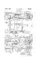
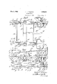
- vvhereinlligure l is a plan view of the machine in po ion on railroad track;
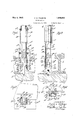
- rieure 2 is a longitudinal vertical cross section, talzen at lineQ-Zof Figure l;
- lligure 3 is. a detailed vert-ical cross sec.- tion, on an enlarged scale, ofthe lower end of the hammer in drivino position, taken at line 3 3 Aof Figure 2;
- Figure 4 is a sectional view generally similar toFigr-.re 3 and talren at- Vline of Figure 3;
- l1" 5 is a transverse cross sectional def ien at line 5 5 of Figure- ;
- V Figure a' is a transverse cross sectional detail taken at line 6-6 of Figure d;
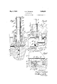
- Fig-ure 8 is a longitudinal vertical cross sectional detail showing the upper end of the hammer mechanism and talen on line 8 8 of Figure lf. on an enlarged scale;
- Figure 9 is-a transverse cross section taken at line 9-9 of Figure S;
- igure l0 is a transverse cross sectional detail taken atline l ⁇ 010 of Figure 8
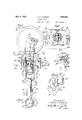
- Figure ll is a longitudinal vertical cross machine shown in Figura ,11, .With parts in;
- Fieurel is a side elevationgoff -the;1nag.f netic spike .holding mechanism Withvparts omitted and parts .in section;
- Figure le is a transverse sectional ldetail taken. at line lillll of Figurevl;
- A il indicaterails supported ./onytiesrAl, A? which are positioned fn.. agroad. bed Aor other. supporting surface. A?.
- Between-the ties andthe rails are tieplatesA, A3..
- the ties are held in placeby Spikes-.A4 which are preferably provided Withiheads A52.' T -he heads may he more Vor.lessoval in plan asin-f dicatedin thedrawings .andpo-sitioned un-V symmetrically uponthe shaft of the fspilrea;
- the :details of the shapeI ofthe spike, how-- ever, forni lno particular ⁇ partof; the present, invention are only shownas illustrating typical railroad spikes :of a ,type lnaw .come inonly in use.
- the tie..l plates areproyided with perforationsi, as shown. i
- the machine is. preferably mounted on a chassis or carriage* which may be formed of side rameinembr B., WhichI are joined Vtogether by a crossmemloer B1.. Positioned on the cross memheradjacenteach of its ends, is a more or less cup-shaped receiving. and supporting member B2.
- ⁇ Axles B3, B3 carrying ⁇ flanged 'Wheels B4, B4 are journaled in the side frame men'ljiers B; Upivardly eXtendir'igy stops B: are positioned oli/each ofthe side'i frame Inembersl- B; In lathe; formof the in@A vention shown inf Figures l1 ande-l2, theside frame members B, at their rear ends, are provided with extensions B6 which carry stops B7 and at their forward ends are provided with extensions B8 which carry laterally extending members B0 from which extend downwardly extending channel members B10.
- Spike engaging springs B11, B12 are preferably mounted adjacent the lower or discharge end of each of the members B10.
- a bar B13 Attached to the cross member B1 preferably at its middle, is a bar B13 provided with a perforation B11 into which a coupling may be inserted.
- a bar B13 By means of the bar the carriage and the machine upon it may be connected to any suitable power source and pulled along.
- C is a relatively flat and extended frame member which carries the spike driving mechanism proper. Extending downwardly from the member C is a spacer C1 which carries an inverted cup-shaped member C2 which rests on a ball C3, which ball is supported in the upwardly faced cup member B2 on the cross member B1 of the truck frame.
- the member C carries a counterweight C4 which tends to depress the end upon which it is positioned.
- the frame member C at the end adjacent the counterweight may be provided with a laterallyextending part C5.
- the member C At its opposite end the member C may be reduced as at C6 and carries an upwardly extending handle member C7.
- Supported on the frame member C are two v Substantially independent nail or spike driving machines. They are arranged so that they may operate simultaneously and thus two spikes may be driven at the same time. Since the spike driving machines and their v driving engines and connections are preferably identical, only one will be described.
- Engines C3 are mounted on the member C.
- the engines carry driving wheels C9 over which are positioned driving belts C10.
- the belts drive fly wheels C11 which are positioned on crank shafts C12 which are journaled in pairs of upwardly extending supporting members C13, C13. Each of these pairs is mounted upon and preferably integral with a base part C12.
- A. belt tightening member C15 is in contact with each belt.
- These members are carried upon arms C10 which are pivotally positioned on the member C as at C17 and are provided with tension springs C12, each of which is fastened at one end to one of the members C10 and at its other end to an eye bolt C10 which is positioned in the member C.
- the member C is provided with two irregularly shaped perforations C20. The shape of these perforations is indicated in dotted lines in Figure 9.
- Bolts C21 extend through the perforations C20 and by means of them the plate C11 is held in place. By reason of the size and shape of the perforation C20 the plate C11 may be moved so as to adjust its position
- D, D are cylinders positioned between each pair of members C13 and they may be integral with those members.
- the cylinders D are provided throughout the major portion of their lengths with slots or openings D1, D1. They are provided with partially closed bottoms D2 from which hollow lextensions D3 project. These extensions are slotted as at D4 and provided with laterally extending pins D3, D2.
- D0 is a second hollow member. As indicated particularly in Figures 3, 4, 7 and 8, it is formed with a relatively longer portion of one diameter and a relatively shorter portion D7 of a larger diameter.
- the portion DG may be of generally squared cross section as indicated in Figures 5 and 6. In the portion D7 are formed two slots D8 which are preferably oppositely placed and through which the pins D5 penetrate.
- the portion DG Adjacent its bottom the portion DG is provided with slots D0 and, preferably above them, with laterally extending pins D10. Along one side throughout the major portion of its length, the portion DG is provided with an elongated slot D11. Ears D12, D12 are formed on the portion D6 and provide pivotal support for arms D13, D13. Adjacenttheirlower ends, the arms D13 are inwardly bent and carry Vcontacting shoes D11, each of which has an upwardly extending shoulder D15 and is provided on its inner face with a groove D10. Compression springs D17 are fastened each at one end upon the portion D0 and bear against the arms D13, tending to force them out. D18 is a collar which is generally rectangular in cross section to correspond in shape to the member D0.
- Tt is also provided with two relatively long slots D20 which extend throughout the major portion of its length and two relatively shorty l ⁇ er slots D21, D21. These latter slots are positioned above the slots D20 and the pins D10 extend through them.
- each crank shaft C12 thereis fastened a connecting rod E.
- This connecting rod engages a cross head E1 from which a member E2 extends downwardly.
- This memberv carries a piston E3.
- E4 is a cushioning cylinder or hammer member slidably mounted within the member D and having slidably mounted within itself the piston E3.
- the cushioning cylinder E4 vis hollow as shown and is provided at its upper end with a removable closing plate E5 wit-hin which is positioned a ball valve E0 which is so shaped and arranged that it will open in response to CLS suction from within and lwillclose in response to pressure from within;i
- the V"closi-ngplate E5 is provided with Aa hollow yinteriorly threaded packing receiving member "EY' with# in whicha packing-Es may be positioned.
- E9 is a packing gland adapteditobe-remov'- ably and 'adjustably seatedin the member'E?.
- the cushioning cylinder Ei provided in its bottom with a strikingpart E1Q and has also a valve El1 which is shaped and arranged to open in response tosu'ction'irom'within and to close in response to' pressure from within.
- F is an anvil block slida'bly mounted within the member' D3 and extending through the hollow members IDSand D7. It maybe provided in its top with a hardened and removable plug F1 and has extendingthrouglr it a pinl. This pin, at each end, projects into the slots D4.
- the lower end of the -anvil block E may be reduced as shown at F3 and provided with a hollow'F shaped to conform to or to accommodate the he'adof the spike which is to be driven.
- the spikes are fed into the machine by hand, being inserted through the slots D, -In the form of 'the deY ice shown in Figures ll to 16, inclusive, an automatic feed is provided.
- Thevehicle frame is essentially the same as ,that shown in 'the earlier tigures ⁇ except as above mentioned the spike ⁇ feeding assemblies B9, 'Bm'a're attached to forwardly entendingp'rojections from the vehicle vframeV members
- the hammering assembly is essentially the sameias 'that described above except that the spike engaging parts are different.
- :'Ihe'hammer F is surrounded and guided by a tubular'member G.
- This member is provided ⁇ with a pair of ears G1 in which a shatt G2 .is ournaled.V
- Mounted on this shaft are arms G3, G awhichlare downwardly bent as at G4 and attached to Vand preferably formed integral-with a magnet housing G5.
- G6, G6 are 'stopsform'ed on ⁇ the member G and projecting laterally therefrom and servingas stops to limitthe downward movement of vthe magnet assembly;
- the magnet is provided withV a contact 'shoe or part G7 which is grooved or notched as at GS to conform Imore or less to the shape of the spike.
- a magnet coil G9 is positioned within the housing G5 and is connected to conductors G10, G1o by means of which current to energize the'magnet is conducted to it by any suitable source.
- rlhe member D6 thus byi-ts own 'weight'slides into the lowest positionl as indicated inl'lligure l.
- the member D18 also moves or .is moved into lthe lower position vshown .in Figi ure d and the shoulders l)15 are engaged b it.
- a spike isins'erted through the slot D11 between the shoes' D14 and is guided and held by them.
- VViththe parts in this position' which is illustrated particularly in Figures 1,2, 3 and l, the operator exerts a downward pressure upon the driving machine, usually by pressing upon the handle C7.
- the 'orward or driving-end of the machine is thus tilted downwardly and 4then when the driving engine is operated, the hammer which rests upon the head of the spike is successively struck bythe strik-ing part E10 of the cushioning piston E4 and the spike is-driven.
- the cushioning pistonf is inserted in order to cushion the hammer blow and the shock in'- cident thereto.
- the arrangement kof the valve and the piston within the cushioning piston is such that an aircushion is provided.
- Each oi the valves is arranged to open only from suction from within so thatair is constantly and positively drawn into the cushioning' piston E4 but is not positively discharged thereiromf It may leak out past the paclring'and it so it will be replaced by air drawn fin -under the influence of suction from within. Air will normally be ⁇ under compression on both'sides ofthe-cushioning E3 within the'cushioningpiston E4. As the driving continues, the spike is driven downward toward the position shown'in Figure 7.
- the machine is somewhat depressed by the operator preferably by pressure upon the handle C1 and it is moved backward and forward or otherwise so as to bring the contacting parts G7 of the magnet into position to engage a spike within the slot or groove G8.
- the machine is then moved laterally sulliciently to position the spike over the appropriate opening in the tie plate and it is then further depressed and the driving operation is commenced.
- the member G of the magnet assembly moves with it.
- the spring G11 contacts Ythe flange of the rail or some other fixed part, and is compressed. At first the compression is not sufficient to overcome the magnetic influence and to separate the magnet from the spike.
- the joint for the support for the driving assembly is in effect a universal joint.
- the ball upon which it is supported may have considerable motion in its supports and thus the frame may be tilted vertically, swung laterally or moved backwards and forwards. This is of importance because it avoids necessity of moving the entire truck to place the spike and to position the hammer assembly properly with relation to the spike.
- the spike By means of my device and by means of movement and adjustment made possible through its use the spike may always be driven straight and vertically instead of being in an inclined position as is often the case with present practice.
- a. movable carriage a spike driving machine, carried pivotally thereby, said carriage provided with a fitting adapted to receive said spike driving machine, said machine being gravitally held upon said fitting, and being readily upwardly removable therefrom, said machine including a support, a. hammer, a hammer guiding assembly and a spike gripping assembly and a generally horizontal supporting frame with which they are unitarily movable, said frame being freely tiltable in relation to the carriage during the normal spike driving operation.
- a spike driver a movable carriage, a spike driving machine, pivotally carried thereby, said carriage provided with a fitting adapted to receive said spike driving machine, said machine being gravitally held upon said itting, and being readily upwardly removable therefrom, said machine including a support, a hammer, a hammer guiding assembly and a spike gripping'assembly, said spike gripping assembly adapted in one position to grip the spike and to be moved to release the spike and a generally horizontal supporting frame with which they are unitarily movable, said frame being freely tiltable in relation to the carriage during the normal spike driving operation.
- Tn al spike driver a movable carriage, a spike driving machine movably carried thereby, said carriage provided with a fitting adapted to receive said spike driving machine, said machine being gravitally held upon said fitting, and being readily upwardly removable therefrom, said machine including a support, a hammer, a hammer guiding assembly and a spike gripping assembly and a generally horizontal supporting frame with which they are unitarily movable, said frame being freely tiltable in relation to the car- K hammer guidin release the Slik@ ably carried thereby, said carriagerprovided with :i itt-ino" s #apted to rece-ive said spike driving machine, said mach i vbeing gravitally ⁇ held upon said fitting', and being readily upwardly removabletherefrom, said machine including a support, a'ham'mer, a
- afmovable carriage a spike Vdriving 'machine Icaia'ried ⁇ thereby,- said carriage provided with a fitting adapted'to receive said spike driving machine, vsaid ma# chine including a support, a. hammer-,a hammer guiding assembly and 'avspike gripping assembly, said spike gripping assembly adapted in one position to Vgripthel spike and adapted to Contact a fixed object outside of the spike driver and thereby to be moved to release the spike.
- a spike driver a movable carriage, a spike driving machine'removabl'y and movably carried thereby, saidfcarriage provided with a plurality of ttings adapted selectively to receive said spike drivingmachine, said machine includn'g a support, a hammer, a hammer guiding assembly and a spike grippino' assembly.
- a spike driver a movable carriage, a spike driving ⁇ machine removably and movably carried thereby, said 'carriage provided with a. plurality oi fittings adapted selectively to receive said spike driving machine, said machine including ay support, 4a hammer, a hammer guidingassembly and a spike gripping assembly, said spike gripping assembly adapted in one position to grip the spike and adapted to Contact a lined object outside of thu spike driver and thereby to be moved to 9,
- a spike driver a movable carriage, a spike driving machine removably and movf carrie-l thereby.
- said carriage provided ,th a plurality or" ritt-ings adapted selectivelj; to receive said spike driving machine, said machine .including a support, a hammer, i the spike driving machine as a vvhole adapted to be tiltedin: rel'ationto: the carriage, a hammer guiding assembly andfa spike gripping asseminaly.V n
- a yspike driver a movable carriage, a spike driving machine- Y vably and movably carried thereby', said carriage :p rovided Witha plural-it offittings vadapted selectively vtio-receives n spille'driviugmachine,said inch g a supportv anda hamm-er, as a -Wholeadapted to-bel the spike driver tilted, a ham-mer guicing assembly and a spike gripping.
- said spike gripping assembly 'adapte-d Vin one position to .grip the spikeaud 4:adapted to Contact iiizedl 'object outsideiof the spike'driver and thereby to 'be' moved to release'thespike.v Y
- a 'spike driver a movablel carriage, a -rspike driving machine removably andmovably carriedthereby, vsaid carriage provided With a plurality of fittings adapted selectively to receive saidspike driving machine, said machine including a support, a driving-engine, a transmission :and a, 'hammenthe spike driver as awvholeadapted tobe-tilted, Ta hammer guidingrassembly and a movable spike gripping assembly, said spike gripping assembly,adapted/in one position to grip the 'spike Vand adapted to vContact a iixed 'object outside of the spike; driver and 'therebyto be 4moved to releaseithe spike;- f
- a spik driver a movable carriage, a spi-ke drivinggmachine Vcarried therebvsaid carriage provided with a iitting adapted to receive saidf'spike 7drivingjinachina V ⁇ sla-id machine including 'a support, 'a hammer, -aharnmer guiding assem'blvand a spike grippiiig assembly,A said spike gripping assembly adapted inonepositionf to grip the spike and to be fmoved'lto releasel the spike, ,said spike gripper embodyingv an lelectro-magnet. 4
- a tiltably mounted platform carrying the spike driving mechanism proper, said mechanism including a hammer, a guide therefor, and a spike gripping assembly, the hammer guide and spike gripper being collapsible and adapted to expand under the iniuence of gravity when free ⁇ to do so.
- a tiltably mounted platform carrying the spike driving mechanism proper, said mechanism including ⁇ a hammer, a guide therefor, and a spike gripping assembly, the hammer guide and spike gripper being collapsible and adapted to expand under the infiuence of gravity when free to do so, in combination with a hammer driving mechanism, including a piston.
- a tiltably mounted platform carrying the spike driving mechanism proper, said mechanism including a hammer, a guide therefor, and a spike gripping assembly, the hammer guide and spike gripper being col lapsible and adapted to expand under the influence of gravity when free to do so, in ecmbination with a hammer driving mechanism, including a piston having within it a cushioning element.
- a tiltably mounted platform carrying the spike driving mechanism proper, said mechanism including a hammer, a guide therefor, and a spike gripping assembly, the hammer guide and spike gripper being collapsible and adapted to expand under the iniiuence of gravity when freevto do so, in combination with a hammer driving mechanism including a piston having within it a cushioning element, and means for driving the piston.
- a. wheeled truck and a movable spike driving assembly removably and adjustably mounted thereon, said spike driving assembly vincluding a supporting frame and carrying a plurality of independently mounted. and independently o perable spike drivers, each of said machines including a power source, a transmission means, ahammer, guiding and ad ⁇ - justing means for said hammer and a spike 'engaging and guiding means,saidspike engaging means adapted in one position of adjustment, to engage and hold the spike and in another adapted automatically to contact a fixed object separate from said machine and to be moved thereby to release the spike.
- the spike driving assembly as a whole being mounted for vertical movement, the spike engaging means provided with a part adapted to contact a fixed member outside of the driving assembly in response to downward movement of that assembly, whereby the spike engaging means is disengaged from the spike.
- the spike driving assembly as a whole being mounted for vertical movement, the spike engaging means provided with a part adapted to contact a fixer member outside of the driving assembly in response to downward move! ment of that assembly, whereby the spike engaging means is disengaged from the spike, said spike engaging means including a swinging member adapted in response to downward movement of the assembly to be swung out of engaging position.
- the spike driving assembly as a whole being mounted for vertical movement, the spike engaging means provided with a part adapted to contact a fixed member outside of the driving assembly in response to downward movement of that assembly, whereby the spike engaging means is disengagedfrom the spike, said spike engaging means including a magnetic swinging member adapted in response to downward movement of the assembly to be swung out of engaging position.V
- the spike driving assembly as a whole being mounted for vertical movement, the spike engaging means provided with a part adapted to contact a fixed member outside of the driving assembly in response to downward movement of that assembly, wherebyl the spike engaging means is disengaged from the spike, said spike engaging means including a magnetic swinging member adapt-ed in response to downward movement of 'the assembly to be swung out of ene (fing position, said magnetic member provided with a spring adapted to be compressed by lowering movement of the driving assembly.
- a spike feeding means adapted to contain and feed a plurality of spikes maximal ⁇ sively to a drivingpoint and a driving as sembly mcvably mounted with respect to said feed, said assembly including a spike engaging means adapted in one position to engage and withdraw a spike from said feed, to hold the spike for Vdriving and adapted as the spike is driven to he moved ont of engagement with the latter,
- a spike feeding means ada pted to con tain and feed a plurality of spii progressivelj,T to a. driving point and a driving assembly movablymounted with respect to said feed, said assembly including a spike engaging means adapted in one position to rassegne-*s engage and Withdraw a spike from said feed, to olc. the spike for driving and adapted is driven to be moved out of ic latter, said feed including members adapt-ed to be e is Withdraw f .g in a spike di-viiig niake iieeding means adapted to oon- Feed a plurality oi spikes stipulate- .LLL d.
- said asrembl including i c engaging mea-ns adapted in one positon 'to n 'l itlidraiv ike from said feed',
- said feed includa spike is Withdrawn, said e' y means including a magnet, 28. ln a spike driver for driving spikes for rai road rails and the like, a movable carriage adapted to travel along the track,
- spike driver frame mounted en the for ready bodily movement in re aten thereto during the nor- U0 mal spike driving operation, and a spike driving a mblv n'iounted upon the trame and mdvable in" 'arily therewith, iii-.cludinga hammer, means therefor, actuating' means tuer and spike gripping means,
- trame being' pivetally supported upo the carriage.
- ring' members adapted to be A err-to during the norrailroad rails and the like, a movablevcar-V spike-gripping means, and .gravitalfme'ans for normally holding said frame with the spike dri-ving' assembly in inoperative position.
- a spike driver for driving spikes for railroad rails ⁇ and the like, a movable carriage adapted totravel along the track, a spiike'driver iframe mounted on 'the carriage ⁇ for bodily movement in relation'thereto, and a spike driving assembly mounted upon 'the frame and movable 'unitarifly therewith, in- ⁇ cludin'g a hammer, guiding Vmeans therefor, actuating means therefor, and Vspike gripping means, and gravital means for normally I'holding said frame With the spike driving' assembly in inoperative position, including 'a y:pivotal mounting VVfor, said tra-me and a counterweight f 32.
- a spike driver In a spike driver, a movable carriage, a generally horizontal' frame tiltably mounted on said carriage for ready movementduring the normal spike ⁇ driving operation, a spike driving machine mounted upon said frame, said machine including a support, a hammer, a hammer guiding assembly and a spike gripping assembly.
- a movable carriage In a spike driver, a movable carriage, a generally horizontal frame tiltably mounted on said carriage for ready movement during the normal spike driving operation, a
- said machine including a support, a hammer, a hammer guiding assembly and a spike gripping assembly, said hammer guiding assembly and spike gripping assembly being unitarily movable with said frame.
- a spike driver machine a movable carriage mounted for movement along the rails of a track, a supporting member for said machine pivotally mounted upon saidcarriage, said machine including a hammer, a hammer guiding assembly and a spike gripping assembly mounted on one'side of its axis of tilt, and driving means for the hammer mounted on the opposite side of the axis of tilt.
- a movable carriage mounted for movement along the rails of a track, a spike driving machine carried thereby, and supporting means for said machine tiltably mounted on said carriage for rotation about an axis extending transversely across said track, said supporting means lbeing manually tiltable toward the Work, and means for gravitally moving said supporting means away from the Work when released.
- a movable carriage mounted for movement yalong' the rails of a track, a supporting member pivotally mounted upon said carriage, said machine including a vfly Wheel, a crank associated With said dy Wheel, a link pivot-ed to said crank, a hammer head pivoted to said link and a guide for said hammer head.
- a movable carriage mounted for movementl along the rails of a track, a supporting member pivotally mounted upon said carriage, said machine including a plurality of fly Wheels, a crank associated with each said fly Wheel, a link pivoted to each said crank, a hammer head pivoted to each said link, guiding means for each hammer head, and means for align* ing spikes in driving position.
Landscapes
- Engineering & Computer Science (AREA)
- Architecture (AREA)
- Civil Engineering (AREA)
- Structural Engineering (AREA)
- Portable Nailing Machines And Staplers (AREA)
Description
May 3, 1932 H. H. 'TALBQYS 1,856,893
SPIKE DRIVER Filed July s, 195o 5 sheetssheet` 1 zB/4 Z 3 @M+ Cli ifa/weit H. H. TALBOYS SPIKE DRIVER May 3, 1932.
Filed July 5, 1930 5 Sheets-Sheet 2 May 3, '1932. H. H. TALBoYs SPIKE DRIVER Filed July 3, 1930 5 Sheets-Shet 6 May 3, 1932. H. H. TALBoYs SPIKE DRIVER Filed July, 1950 5 Sheets-Sheet 4 In vena?. Jzfew y May 3, 1932.
H. H. TALBoYs I 1,856,893
SPIKE DRIVER Filed July 3, 1950 5 Sheets-Sheet 5 .i spi lies.
Patented May 3, 1932 kFrio'runind centenar, ei i.
iluminan, Wisconsin, Vn ociiienafrion @WISCONSIN Sammlern .Application filed July 3, 1930,.' Serial No. 4565583.l
This invention relates o :inail or spike driver andthe Vform illustrated herewith is particularly intended for use as a spike driving machine for ydriving railroad spikes, although the apparatus andthe principles involved may be used in many other connections.
The invention has for .one object to pro.- vide a movable means for driving railroad Another. object is to provide such a means Whi h may be moved along. railroad tracks and used to spike them in place, inn other ohect is toV providea powerdriven spilze di ving machine, and a vfurther object is to provide a power driven, automatically` Qed, hand controlled spike driving machine. @ther objects. -will appear from time to time in the course oit the specihcation andy claims.
My invention is illustrated more or less diagrammati'cally in the accompanying drawings, vvhereinlligure l is a plan view of the machine in po ion on railroad track;
lligure 3 is. a detailed vert-ical cross sec.- tion, on an enlarged scale, ofthe lower end of the hammer in drivino position, taken at line 3 3 Aof Figure 2;
Figure 4 is a sectional view generally similar toFigr-.re 3 and talren at- Vline of Figure 3;
l1" 5 is a transverse cross sectional def ien at line 5 5 of Figure- ;V Figure a' is a transverse cross sectional detail taken at line 6-6 of Figure d;
'Figure T'is a `vieiv..generally .similar .to Figure d, showing the spike at the end of the driving, With the parts in the position which they occupy at that time;
Fig-ure 8 is a longitudinal vertical cross sectional detail showing the upper end of the hammer mechanism and talen on line 8 8 of Figure lf. on an enlarged scale;
Figure 9 is-a transverse cross section taken at line 9-9 of Figure S;
igure l0 is a transverse cross sectional detail taken atline l`010 of Figure 8 Figure ll is a longitudinal vertical cross machine shown in Figura ,11, .With parts in;
section;
Fieurel is a side elevationgoff -the;1nag.f netic spike .holding mechanism Withvparts omitted and parts .in section;
Figure le is a transverse sectional ldetail taken. at line lillll of Figurevl;
igure lis Ian enlarged detail shown inV plan of the loverdischargeend oltthespikez Yfeeding mechanism with `parts, omitted and, parts in,` section.
Figure lo, .is .a transverse vertical -cress sectional? detail taken.- .ft @line lifl OftF-gr une l5, K l Like parts aredesignated bylikecharac-I ters. .thnQ-,Ilghout the -Speccaton anddraw- :ln-gs.'
A, il indicaterails supported ./onytiesrAl, A? which are positioned fn.. agroad. bed Aor other. supporting surface. A?. Between-the ties andthe rails are tieplatesA, A3.. The ties are held in placeby Spikes-.A4 which are preferably provided Withiheads A52.' T -he heads may he more Vor.lessoval in plan asin-f dicatedin thedrawings .andpo-sitioned un-V symmetrically uponthe shaft of the fspilrea; The :details of the shapeI ofthe spike, how-- ever, forni lno particular` partof; the present, invention are only shownas illustrating typical railroad spikes :of a ,type lnaw .come inonly in use. The tie..l plates areproyided with perforationsi, as shown. i
The machine is. preferably mounted on a chassis or carriage* which may be formed of side rameinembr B., WhichI are joined Vtogether by a crossmemloer B1.. Positioned on the cross memheradjacenteach of its ends, is a more or less cup-shaped receiving. and supporting member B2. `Axles B3, B3 carrying` flanged 'Wheels B4, B4 are journaled in the side frame men'ljiers B; Upivardly eXtendir'igy stops B: are positioned oli/each ofthe side'i frame Inembersl- B; In lathe; formof the in@A vention shown inf Figures l1 ande-l2, theside frame members B, at their rear ends, are provided with extensions B6 which carry stops B7 and at their forward ends are provided with extensions B8 which carry laterally extending members B0 from which extend downwardly extending channel members B10. Spike engaging springs B11, B12 are preferably mounted adjacent the lower or discharge end of each of the members B10. Attached to the cross member B1 preferably at its middle, is a bar B13 provided with a perforation B11 into which a coupling may be inserted. By means of the bar the carriage and the machine upon it may be connected to any suitable power source and pulled along.
C is a relatively flat and extended frame member which carries the spike driving mechanism proper. Extending downwardly from the member C is a spacer C1 which carries an inverted cup-shaped member C2 which rests on a ball C3, which ball is supported in the upwardly faced cup member B2 on the cross member B1 of the truck frame.
At one end the member C carries a counterweight C4 which tends to depress the end upon which it is positioned. The frame member C at the end adjacent the counterweight, may be provided with a laterallyextending part C5. At its opposite end the member C may be reduced as at C6 and carries an upwardly extending handle member C7. Supported on the frame member C are two v Substantially independent nail or spike driving machines. They are arranged so that they may operate simultaneously and thus two spikes may be driven at the same time. Since the spike driving machines and their v driving engines and connections are preferably identical, only one will be described.
Engines C3 are mounted on the member C.
The engines carry driving wheels C9 over which are positioned driving belts C10. The belts drive fly wheels C11 which are positioned on crank shafts C12 which are journaled in pairs of upwardly extending supporting members C13, C13. Each of these pairs is mounted upon and preferably integral with a base part C12. A. belt tightening member C15 is in contact with each belt. These members are carried upon arms C10 which are pivotally positioned on the member C as at C17 and are provided with tension springs C12, each of which is fastened at one end to one of the members C10 and at its other end to an eye bolt C10 which is positioned in the member C. The member C is provided with two irregularly shaped perforations C20. The shape of these perforations is indicated in dotted lines inFigure 9. Bolts C21 extend through the perforations C20 and by means of them the plate C11 is held in place. By reason of the size and shape of the perforation C20 the plate C11 may be moved so as to adjust its position.
C22 are washers positioned beneath the member C and engaging the bolts C21.
D, D are cylinders positioned between each pair of members C13 and they may be integral with those members. The cylinders D are provided throughout the major portion of their lengths with slots or openings D1, D1. They are provided with partially closed bottoms D2 from which hollow lextensions D3 project. These extensions are slotted as at D4 and provided with laterally extending pins D3, D2. D0 is a second hollow member. As indicated particularly in Figures 3, 4, 7 and 8, it is formed with a relatively longer portion of one diameter and a relatively shorter portion D7 of a larger diameter. The portion DG may be of generally squared cross section as indicated in Figures 5 and 6. In the portion D7 are formed two slots D8 which are preferably oppositely placed and through which the pins D5 penetrate. Adjacent its bottom the portion DG is provided with slots D0 and, preferably above them, with laterally extending pins D10. Along one side throughout the major portion of its length, the portion DG is provided with an elongated slot D11. Ears D12, D12 are formed on the portion D6 and provide pivotal support for arms D13, D13. Adjacenttheirlower ends, the arms D13 are inwardly bent and carry Vcontacting shoes D11, each of which has an upwardly extending shoulder D15 and is provided on its inner face with a groove D10. Compression springs D17 are fastened each at one end upon the portion D0 and bear against the arms D13, tending to force them out. D18 is a collar which is generally rectangular in cross section to correspond in shape to the member D0. It is positioned about the lower end of that member and is provided with a slot D10 corresponding to the slot D11 in the member D0. Tt is also provided with two relatively long slots D20 which extend throughout the major portion of its length and two relatively shorty l` er slots D21, D21. These latter slots are positioned above the slots D20 and the pins D10 extend through them.
T have now described the hammer guiding and spike engaging and guiding assembly. I shall next describe the hammering mechanism.
To the throw of each crank shaft C12 thereis fastened a connecting rod E. This connecting rod engages a cross head E1 from which a member E2 extends downwardly. This membervcarries a piston E3. E4 is a cushioning cylinder or hammer member slidably mounted within the member D and having slidably mounted within itself the piston E3. The cushioning cylinder E4 vis hollow as shown and is provided at its upper end with a removable closing plate E5 wit-hin which is positioned a ball valve E0 which is so shaped and arranged that it will open in response to CLS suction from within and lwillclose in response to pressure from within;i The V"closi-ngplate E5 is provided with Aa hollow yinteriorly threaded packing receiving member "EY' with# in whicha packing-Es may be positioned. E9 is a packing gland adapteditobe-remov'- ably and 'adjustably seatedin the member'E?. The cushioning cylinder Ei provided in its bottom with a strikingpart E1Q and has also a valve El1 which is shaped and arranged to open in response tosu'ction'irom'within and to close in response to' pressure from within. F is an anvil block slida'bly mounted within the member' D3 and extending through the hollow members IDSand D7. It maybe provided in its top with a hardened and removable plug F1 and has extendingthrouglr it a pinl. This pin, at each end, projects into the slots D4. The lower end of the -anvil block Emay be reduced as shown at F3 and provided with a hollow'F shaped to conform to or to accommodate the he'adof the spike which is to be driven.
In the form of the invention shown in Figures l to l0, inclusive, the spikes are fed into the machine by hand, being inserted through the slots D, -In the form of 'the deY ice shown in Figures ll to 16, inclusive, an automatic feed is provided. Thevehicle frame is essentially the same as ,that shown in 'the earlier tigures `except as above mentioned the spike `feeding assemblies B9, 'Bm'a're attached to forwardly entendingp'rojections from the vehicle vframeV members In v.this modified form of the invention, the hammering assembly is essentially the sameias 'that described above except that the spike engaging parts are different. :'Ihe'hammer F is surrounded and guided by a tubular'member G. This member is provided `with a pair of ears G1 in which a shatt G2 .is ournaled.V Mounted on this shaft are arms G3, G awhichlare downwardly bent as at G4 and attached to Vand preferably formed integral-with a magnet housing G5. G6, G6 are 'stopsform'ed on `the member G and projecting laterally therefrom and servingas stops to limitthe downward movement of vthe magnet assembly; The magnet is provided withV a contact 'shoe or part G7 which is grooved or notched as at GS to conform Imore or less to the shape of the spike. A magnet coil G9 is positioned within the housing G5 and is connected to conductors G10, G1o by means of which current to energize the'magnet is conducted to it by any suitable source. This-might, `for example*y be the magneto which is usedin connec tion withthe driving engine; spring G11 is mounted on the'bottom of the housing G5 so as to contact the flange of the rail.
It will be realized that while I have herewith shown anddescribed a practical operative device, nevertheless many changesmight he made'in the size, shape. number and disposition oi parts without ldeparting from the spirit of my invention and therefore I wish that vmy showing be taken as in a sense diagrammatic. In particular, although I have shown only a single spike:drivingassembly mounted on the 'trucl,"obviously`two might beused-together and they might be operated in any manner suitable. Iii-particular any typezof hammer drive might-be used. For many purposes it is Aadvisable to use internal combustion" engines which I have shown. vHowever, torvsome purposes it is possible to use a pneumatic or a solenoid or other elecL trichammer, or internal combustion hammer. f
The use and operation of my invention are as follows 2' f I-shall iirst describe the use and operation offtheinvention in Vthe form illustrated in Figures 1 to 10, inclusive. When it is desired to use the machineito dri-ve spikes ina railroad, the parts -are assembled as shownin Figures'l and 2. The machine is put jupon the rails and moved-'to the'place where it is :to be 'used The parts gare s o'proportionled that the machine is heavy at the :rear or engine end and thus unless it is positivelydepressed at the other end, it automatically tilts rearwardly and raises the" driving mechanism out Contact with the rail. rlhe member D6 thus byi-ts own 'weight'slides into the lowest positionl as indicated inl'lligure l. At this time, also, the member D18 also moves or .is moved into lthe lower position vshown .in Figi ure d and the shoulders l)15 are engaged b it. A spike isins'erted through the slot D11 between the shoes' D14 and is guided and held by them. VViththe parts in this position', which is illustrated particularly in Figures 1,2, 3 and l, the operator exerts a downward pressure upon the driving machine, usually by pressing upon the handle C7. The 'orward or driving-end of the machine is thus tilted downwardly and 4then when the driving engine is operated, the hammer which rests upon the head of the spike is successively struck bythe strik-ing part E10 of the cushioning piston E4 and the spike is-driven. The cushioning pistonfis inserted in order to cushion the hammer blow and the shock in'- cident thereto. The arrangement kof the valve and the piston within the cushioning piston is such that an aircushion is provided. Each oi the valves is arranged to open only from suction from within so thatair is constantly and positively drawn into the cushioning' piston E4 but is not positively discharged thereiromf It may leak out past the paclring'and it so it will be replaced by air drawn fin -under the influence of suction from within. Air will normally be `under compression on both'sides ofthe-cushioning E3 within the'cushioningpiston E4. As the driving continues, the spike is driven downward toward the position shown'in Figure 7.
Jlifter it has been drivendown a certain dismember DG, however, continues to move down 'ell and thus the arms D13 which are pivoted on D8 move downward and the shoulders D15 escape from contact with the portions of the member D1S which have held them as shown in Figure Ll, and when they are free to do so, they swing outwardly under the influence of the springs D17 into the position shown in Figure 'l'. They thus no longer hold or contact the spike and as the hammering continues the spike may be freely driven to its final position.
In the form of the invention shown in Figures 11 to 16, inclusive, a certain number of spikes are inserted in the slots of the spike carrying members B1". They tend to move 1 downward by gravity and this tendency is increased due to the shock or jar or shaking which the machine undergoes, during hammering. Thus partially by gravity and partially because of this shaking, the spikes are fed steadily downward toward the nailing position. Accidental discharge of the spikes is prevented by means of the springs B11, B12 at the discharge end of the feeders. When driving is to be done with this modied form of the invention, the magnet assembly is moved into the position shown in full lines in Figure 13. The machine is somewhat depressed by the operator preferably by pressure upon the handle C1 and it is moved backward and forward or otherwise so as to bring the contacting parts G7 of the magnet into position to engage a spike within the slot or groove G8. The machine is then moved laterally sulliciently to position the spike over the appropriate opening in the tie plate and it is then further depressed and the driving operation is commenced. As the spike moves downward under the influence of the hammer, the member G of the magnet assembly moves with it. After a certain amount of movement, the spring G11 contacts Ythe flange of the rail or some other fixed part, and is compressed. At first the compression is not sufficient to overcome the magnetic influence and to separate the magnet from the spike. As the downward movement continues, however, a point is reached at which the spring is compressed suiiiciently so that it overcomes the magnetism and the magnet assembly is in ei'lect snapped7 out of contact with the spike and into or toward the dotted line position of Figure 13. The magnet assembly being now out of contact with the spike and out of the way of the hammer, the spike may be driven home. lil/Then the parts are again raised for driving another spike, the magnet will return to its spike engaging or full line position as shown in Figure 13. Tn either form of the device the hammering assembly as carried by therframe member C, maybe positioned on either side of the machine, that is to say, it may be lifted so as to occupy either one of the cup-shaped supporting members B2. Thus it may be used to drive spikes along one rail or along' another. Y
The joint for the support for the driving assembly is in effect a universal joint. The ball upon which it is supported may have considerable motion in its supports and thus the frame may be tilted vertically, swung laterally or moved backwards and forwards. This is of importance because it avoids necessity of moving the entire truck to place the spike and to position the hammer assembly properly with relation to the spike. By means of my device and by means of movement and adjustment made possible through its use the spike may always be driven straight and vertically instead of being in an inclined position as is often the case with present practice.
l claim:
1. In a spike driver, a. movable carriage, a spike driving machine, carried pivotally thereby, said carriage provided with a fitting adapted to receive said spike driving machine, said machine being gravitally held upon said fitting, and being readily upwardly removable therefrom, said machine including a support, a. hammer, a hammer guiding assembly and a spike gripping assembly and a generally horizontal supporting frame with which they are unitarily movable, said frame being freely tiltable in relation to the carriage during the normal spike driving operation.
2. ln a spike driver, a movable carriage, a spike driving machine, pivotally carried thereby, said carriage provided with a fitting adapted to receive said spike driving machine, said machine being gravitally held upon said itting, and being readily upwardly removable therefrom, said machine including a support, a hammer, a hammer guiding assembly and a spike gripping'assembly, said spike gripping assembly adapted in one position to grip the spike and to be moved to release the spike and a generally horizontal supporting frame with which they are unitarily movable, said frame being freely tiltable in relation to the carriage during the normal spike driving operation.
3. Tn al spike driver, a movable carriage, a spike driving machine movably carried thereby, said carriage provided with a fitting adapted to receive said spike driving machine, said machine being gravitally held upon said fitting, and being readily upwardly removable therefrom, said machine including a support, a hammer, a hammer guiding assembly and a spike gripping assembly and a generally horizontal supporting frame with which they are unitarily movable, said frame being freely tiltable in relation to the car- K hammer guidin release the Slik@ ably carried thereby, said carriagerprovided with :i itt-ino" s #apted to rece-ive said spike driving machine, said mach i vbeing gravitally `held upon said fitting', and being readily upwardly removabletherefrom, said machine including a support, a'ham'mer, a
assembly and` a spike gripping assembly and a generally horizontal supporting'frame Vwith which they are' unitarily movable, said 'frame bei-no* freely tiltable in relation'to the carriage*duringsthe normal spike driving operation.`
5. In a lspike driver, a. movable carriage,a spike driving machine nrof'vably carried thereby, said carriage provided with a fitting adapted 'to Vreceive said spike fclrivingfmachine, said machine being gravitally :held upon said tting, and being readily upvv'ardly removable the eflirom, said mac'hine'includi ing a support anda l1-animer, 'the spike driving machine las a Whole 'tiltablymounted on the. carriage for ready movement during the normal spike driving operatiomahammer guiding assembly and fa'spike-rgrippi'ng l'assembly. Y
6. In a spike driver, afmovable carriage,- a spike Vdriving 'machine Icaia'ried `thereby,- said carriage provided with a fitting adapted'to receive said spike driving machine, vsaid ma# chine including a support, a. hammer-,a hammer guiding assembly and 'avspike gripping assembly, said spike gripping assembly adapted in one position to Vgripthel spike and adapted to Contact a fixed object outside of the spike driver and thereby to be moved to release the spike.
7. In a spike driver, a movable carriage, a spike driving machine'removabl'y and movably carried thereby, saidfcarriage provided with a plurality of ttings adapted selectively to receive said spike drivingmachine, said machine includn'g a support, a hammer, a hammer guiding assembly and a spike grippino' assembly.
8. In a. spike driver, a movable carriage, a spike driving` machine removably and movably carried thereby, said 'carriage provided with a. plurality oi fittings adapted selectively to receive said spike driving machine, said machine including ay support, 4a hammer, a hammer guidingassembly and a spike gripping assembly, said spike gripping assembly adapted in one position to grip the spike and adapted to Contact a lined object outside of thu spike driver and thereby to be moved to 9, In a spike driver, a movable carriage, a spike driving machine removably and movf carrie-l thereby. said carriage provided ,th a plurality or" ritt-ings adapted selectivelj; to receive said spike driving machine, said machine .including a support, a hammer, i the spike driving machine as a vvhole adapted to be tiltedin: rel'ationto: the carriage, a hammer guiding assembly andfa spike gripping asseminaly.V n
l0. In a yspike driver, a movable carriage, a spike driving machine- Y vably and movably carried thereby', said carriage :p rovided Witha plural-it offittings vadapted selectively vtio-receives n spille'driviugmachine,said inch g a supportv anda hamm-er, as a -Wholeadapted to-bel the spike driver tilted, a ham-mer guicing assembly and a spike gripping. assembly, said spike gripping assembly 'adapte-d Vin one position to .grip the spikeaud 4:adapted to Contact iiizedl 'object outsideiof the spike'driver and thereby to 'be' moved to release'thespike.v Y
11.-! In.' a 'spike driver, a movablel carriage, a -rspike driving machine removably andmovably carriedthereby, vsaid carriage provided With a plurality of fittings adapted selectively to receive saidspike driving machine, said machine including a support, a driving-engine, a transmission :and a, 'hammenthe spike driver as awvholeadapted tobe-tilted, Ta hammer guidingrassembly and a movable spike gripping assembly, said spike gripping assembly,adapted/in one position to grip the 'spike Vand adapted to vContact a iixed 'object outside of the spike; driver and 'therebyto be 4moved to releaseithe spike;- f
l2. In a spik driver, a movable carriage, a spi-ke drivinggmachine Vcarried therebvsaid carriage provided with a iitting adapted to receive saidf'spike 7drivingjinachina V`sla-id machine including 'a support, 'a hammer, -aharnmer guiding assem'blvand a spike grippiiig assembly,A said spike gripping assembly adapted inonepositionf to grip the spike and to be fmoved'lto releasel the spike, ,said spike gripper embodyingv an lelectro-magnet. 4
13S In a spike driver, a movable carriage, aspike-drivinp; machine carried thereby', said carriage provided with a fitting adaptedto receive saidfspike driving machine, said 'machine including a support, a hammer, a hammer guiding-'assembly and la spike Vgripping assembly,k said' spike l gripping assembly adapted in one lposition to fo'rip thespike and adapted't'ocontact a liked objectoutside of thespike drivery and thereby to ybe Ymoved to release thespike, said spike gripper emblodyspike and adapted to Contact a xed object outside of the spike driver and thereby to be moved to release the spike, said spike gripper embodying an electro-magnet.
15. In combination in a spike driving machine, a tiltably mounted platform carrying the spike driving mechanism proper, said mechanism including a hammer, a guide therefor, and a spike gripping assembly, the hammer guide and spike gripper being collapsible and adapted to expand under the iniuence of gravity when free `to do so.
17. In combination in a spike driving machine, a tiltably mounted platform carrying the spike driving mechanism proper, said mechanism including a hammer, a guide therefor, and a spike gripping assembly, the hammer guide and spike gripper being col lapsible and adapted to expand under the influence of gravity when free to do so, in ecmbination with a hammer driving mechanism, including a piston having within it a cushioning element. A Y
18. In combination in a spike driving machine, a tiltably mounted platform carrying the spike driving mechanism proper, said mechanism including a hammer, a guide therefor, and a spike gripping assembly, the hammer guide and spike gripper being collapsible and adapted to expand under the iniiuence of gravity when freevto do so, in combination with a hammer driving mechanism including a piston having within it a cushioning element, and means for driving the piston.
. 19. In a movable'spike driving machine, a. wheeled truck and a movable spike driving assembly, removably and adjustably mounted thereon, said spike driving assembly vincluding a supporting frame and carrying a plurality of independently mounted. and independently o perable spike drivers, each of said machines including a power source, a transmission means, ahammer, guiding and ad`- justing means for said hammer and a spike 'engaging and guiding means,saidspike engaging means adapted in one position of adjustment, to engage and hold the spike and in another adapted automatically to contact a fixed object separate from said machine and to be moved thereby to release the spike.
20.' In combination in av spike driving ma chine, a hammer and a spike engaging means, the spike driving assembly as a whole being mounted for vertical movement, the spike engaging means provided with a part adapted to contact a fixed member outside of the driving assembly in response to downward movement of that assembly, whereby the spike engaging means is disengaged from the spike.
21. In combination in a spike driving machine, a hammer and a spike engaging means, the spike driving assembly as a whole being mounted for vertical movement, the spike engaging means provided with a part adapted to contact a fixer member outside of the driving assembly in response to downward move! ment of that assembly, whereby the spike engaging means is disengaged from the spike, said spike engaging means including a swinging member adapted in response to downward movement of the assembly to be swung out of engaging position.
22. .In combination in a. spike driving machine, a hammer and a spike engaging means, the spike driving assembly as a whole being mounted for vertical movement, the spike engaging means provided with a part adapted to contact a fixed member outside of the driving assembly in response to downward movement of that assembly, whereby the spike engaging means is disengagedfrom the spike, said spike engaging means including a magnetic swinging member adapted in response to downward movement of the assembly to be swung out of engaging position.V
23. In combination in a spike driving machine, a hammer and a spike engaging means, the spike driving assembly as a whole being mounted for vertical movement, the spike engaging means provided with a part adapted to contact a fixed member outside of the driving assembly in response to downward movement of that assembly, wherebyl the spike engaging means is disengaged from the spike, said spike engaging means including a magnetic swinging member adapt-ed in response to downward movement of 'the assembly to be swung out of ene (fing position, said magnetic member provided with a spring adapted to be compressed by lowering movement of the driving assembly.
24. In combination in a spike driving ma chine, a spike feeding means adapted to contain and feed a plurality of spikes progres` sively to a drivingpoint and a driving as sembly mcvably mounted with respect to said feed, said assembly including a spike engaging means adapted in one position to engage and withdraw a spike from said feed, to hold the spike for Vdriving and adapted as the spike is driven to he moved ont of engagement with the latter,
25. In combination in a. spike driving machine, a spike feeding means ada pted to con tain and feed a plurality of spii progressivelj,T to a. driving point and a driving assembly movablymounted with respect to said feed, said assembly including a spike engaging means adapted in one position to rassegne-*s engage and Withdraw a spike from said feed, to olc. the spike for driving and adapted is driven to be moved out of ic latter, said feed including members adapt-ed to be e is Withdraw f .g in a spike di-viiig niake iieeding means adapted to oon- Feed a plurality oi spikes progres- .LLL d.
u with respeA said feed, said asrembl; including i c engaging mea-ns adapted in one positon 'to n 'l itlidraiv ike from said feed',
. and adapted is driven to be moved out of with the latterI qui the latter, said feed includa spike is Withdrawn, said e' y means including a magnet, 28. ln a spike driver for driving spikes for rai road rails and the like, a movable carriage adapted to travel along the track,
horizontal spike driver trame the carraoe for ready bodily' movement in relation tl mal spike driv'ug o @tici/1, and a spike d-,rivingassembly mounted upon the trame and movable unita 'ily therewith, including hammer, guiding means therefor, actuating means therer ant sp' `e grlp'nng means.
Q9. In a spike driver for driving spikes for riage adapted to travel along the track, a
generally horizontal spike driver frame mounted en the for ready bodily movement in re aten thereto during the nor- U0 mal spike driving operation, and a spike driving a mblv n'iounted upon the trame and mdvable in" 'arily therewith, iii-.cludinga hammer, means therefor, actuating' means tuer and spike gripping means,
trame being' pivetally supported upo the carriage.
30. In a spike driver Jfor driving spikes for railroad rails and the like, movable carriage adapted to travel along the track,
SQ a spike driver frame mounted on the carriage for bodily movement in relation thereto, and a spike driving assembly mounted upon the t'rame and movable unitarily therewith, inc
.L luding a hammer, guiding means thereto actuating means therefor, and
ring' members, adapted to be A err-to during the norrailroad rails and the like, a movablevcar-V spike-gripping means, and .gravitalfme'ans for normally holding said frame with the spike dri-ving' assembly in inoperative position.
31. Ina spike driver for driving spikes for railroad rails `and the like, a movable carriage adapted totravel along the track, a spiike'driver iframe mounted on 'the carriage `for bodily movement in relation'thereto, and a spike driving assembly mounted upon 'the frame and movable 'unitarifly therewith, in- `cludin'g a hammer, guiding Vmeans therefor, actuating means therefor, and Vspike gripping means, and gravital means for normally I'holding said frame With the spike driving' assembly in inoperative position, including 'a y:pivotal mounting VVfor, said tra-me and a counterweight f 32. In a spike driver, a movable carriage, a generally horizontal' frame tiltably mounted on said carriage for ready movementduring the normal spike` driving operation, a spike driving machine mounted upon said frame, said machine including a support, a hammer, a hammer guiding assembly and a spike gripping assembly.
33. In a spike driver, a movable carriage, a generally horizontal frame tiltably mounted on said carriage for ready movement during the normal spike driving operation, a
spike driving machine mounted upon said.
frame, said machine including a support, a hammer, a hammer guiding assembly and a spike gripping assembly, said hammer guiding assembly and spike gripping assembly being unitarily movable with said frame.
34;. In a spike driver machine, a movable carriage mounted for movement along the rails of a track, a supporting member for said machine pivotally mounted upon saidcarriage, said machine including a hammer, a hammer guiding assembly and a spike gripping assembly mounted on one'side of its axis of tilt, and driving means for the hammer mounted on the opposite side of the axis of tilt.
35. In a spike driver machine, a movable carriage mounted for movement along the rails of a track, a spike driving machine carried thereby, and supporting means for said machine tiltably mounted on said carriage for rotation about an axis extending transversely across said track, said supporting means lbeing manually tiltable toward the Work, and means for gravitally moving said supporting means away from the Work when released.
36. In a spike driver machine, a movable carriage mounted for movement yalong' the rails of a track, a supporting member pivotally mounted upon said carriage, said machine including a vfly Wheel, a crank associated With said dy Wheel, a link pivot-ed to said crank, a hammer head pivoted to said link and a guide for said hammer head.
87. In a spike driver machine, a movable ,dem
' fio carriage mounted Jfor movement along the rails of ay track, a supporting member pivotally mounted upon said carriage, said machine including a iy Wheel, a crank associated With said fly Wheel, a link pivoted t-o said crank, a hammer head pivoted to said link and a guide for said hammer head, and means for aligning spikes in driving position.
38. In a spike driver machine, a movable carriage mounted for movementl along the rails of a track, a supporting member pivotally mounted upon said carriage, said machine including a plurality of fly Wheels, a crank associated with each said fly Wheel, a link pivoted to each said crank, a hammer head pivoted to each said link, guiding means for each hammer head, and means for align* ing spikes in driving position.
Signed at Milwaukee, county of hilvvaw kee and State of lVsconsin, this 14th day of June, 1930.
HENRY H. TALBOYS.
Priority Applications (1)
| Application Number | Priority Date | Filing Date | Title |
|---|---|---|---|
| US465583A US1856893A (en) | 1930-07-03 | 1930-07-03 | Spike driver |
Applications Claiming Priority (1)
| Application Number | Priority Date | Filing Date | Title |
|---|---|---|---|
| US465583A US1856893A (en) | 1930-07-03 | 1930-07-03 | Spike driver |
Publications (1)
| Publication Number | Publication Date |
|---|---|
| US1856893A true US1856893A (en) | 1932-05-03 |
Family
ID=23848367
Family Applications (1)
| Application Number | Title | Priority Date | Filing Date |
|---|---|---|---|
| US465583A Expired - Lifetime US1856893A (en) | 1930-07-03 | 1930-07-03 | Spike driver |
Country Status (1)
| Country | Link |
|---|---|
| US (1) | US1856893A (en) |
Cited By (11)
| Publication number | Priority date | Publication date | Assignee | Title |
|---|---|---|---|---|
| US2575535A (en) * | 1946-05-16 | 1951-11-20 | Nordberg Manufacturing Co | Spike hammer |
| US2597337A (en) * | 1948-09-23 | 1952-05-20 | Kershaw Knox | Railway track tool |
| US2742258A (en) * | 1953-12-14 | 1956-04-17 | Lloyd C Rosasco | Fence post driver |
| US2759505A (en) * | 1953-12-14 | 1956-08-21 | Robert H Abbott | Railroad tie adzing machine |
| US2910010A (en) * | 1956-08-02 | 1959-10-27 | American Brake Shoe Co | Impacting apparatus |
| US3010407A (en) * | 1955-05-18 | 1961-11-28 | American Brake Shoe Co | Impacting apparatus |
| US3158867A (en) * | 1961-05-17 | 1964-12-01 | Lloyd E Moss | Spike setting device |
| US3163122A (en) * | 1961-03-06 | 1964-12-29 | Fairmont Railway Motors Inc | Apparatus for setting and driving railroad spikes |
| US3257962A (en) * | 1962-03-02 | 1966-06-28 | Railway Maintenance Corp | Railway track spiking machine |
| US3753404A (en) * | 1970-09-21 | 1973-08-21 | J Bryan | Spike driving system |
| US4928600A (en) * | 1988-11-17 | 1990-05-29 | Harsco Corporation | Railroad spike holding apparatus with acute angled jaws |
-
1930
- 1930-07-03 US US465583A patent/US1856893A/en not_active Expired - Lifetime
Cited By (11)
| Publication number | Priority date | Publication date | Assignee | Title |
|---|---|---|---|---|
| US2575535A (en) * | 1946-05-16 | 1951-11-20 | Nordberg Manufacturing Co | Spike hammer |
| US2597337A (en) * | 1948-09-23 | 1952-05-20 | Kershaw Knox | Railway track tool |
| US2742258A (en) * | 1953-12-14 | 1956-04-17 | Lloyd C Rosasco | Fence post driver |
| US2759505A (en) * | 1953-12-14 | 1956-08-21 | Robert H Abbott | Railroad tie adzing machine |
| US3010407A (en) * | 1955-05-18 | 1961-11-28 | American Brake Shoe Co | Impacting apparatus |
| US2910010A (en) * | 1956-08-02 | 1959-10-27 | American Brake Shoe Co | Impacting apparatus |
| US3163122A (en) * | 1961-03-06 | 1964-12-29 | Fairmont Railway Motors Inc | Apparatus for setting and driving railroad spikes |
| US3158867A (en) * | 1961-05-17 | 1964-12-01 | Lloyd E Moss | Spike setting device |
| US3257962A (en) * | 1962-03-02 | 1966-06-28 | Railway Maintenance Corp | Railway track spiking machine |
| US3753404A (en) * | 1970-09-21 | 1973-08-21 | J Bryan | Spike driving system |
| US4928600A (en) * | 1988-11-17 | 1990-05-29 | Harsco Corporation | Railroad spike holding apparatus with acute angled jaws |
Similar Documents
| Publication | Publication Date | Title |
|---|---|---|
| US1856893A (en) | Spike driver | |
| US3690264A (en) | Mobile track working apparatus | |
| US2018129A (en) | Spike driving machine | |
| US1552757A (en) | Suspension device for vehicles with traveling tracks | |
| US2082594A (en) | Machine for digging ballast | |
| US3401642A (en) | Automatic jacking, levelling and lining railroad track tampers | |
| US1445486A (en) | Air spring | |
| US1415194A (en) | Tie-tamping machine | |
| US2634979A (en) | Bowling pin respotter | |
| US2482796A (en) | Ballast tamping machine for railways | |
| US4522127A (en) | Railway tie plug driving apparatus | |
| US3120195A (en) | Railway track spiking machine | |
| US3553859A (en) | Ballast cribber | |
| US3066913A (en) | Rail spike puller | |
| US2758734A (en) | Straddle truck-mounted material gripping and handling device | |
| US1661969A (en) | Tile-receiving machine | |
| US2818176A (en) | Vehicle mounted magnet | |
| US1347943A (en) | Railroad spiking-machine | |
| US3163122A (en) | Apparatus for setting and driving railroad spikes | |
| US3196803A (en) | Mobile track aligning machine and method | |
| US1351106A (en) | Tamping-machine | |
| US1444115A (en) | Truck | |
| US1556604A (en) | Tamping or ballasting machine | |
| GB802795A (en) | Mobile track-packing machine | |
| US2117561A (en) | Safety lift device for snow plows |