US1856891A - Method and apparatus for gas lift - Google Patents
Method and apparatus for gas lift Download PDFInfo
- Publication number
- US1856891A US1856891A US455913A US45591330A US1856891A US 1856891 A US1856891 A US 1856891A US 455913 A US455913 A US 455913A US 45591330 A US45591330 A US 45591330A US 1856891 A US1856891 A US 1856891A
- Authority
- US
- United States
- Prior art keywords
- gas
- oil
- pipe
- pressure
- valve
- Prior art date
- Legal status (The legal status is an assumption and is not a legal conclusion. Google has not performed a legal analysis and makes no representation as to the accuracy of the status listed.)
- Expired - Lifetime
Links
Images
Classifications
-
- F—MECHANICAL ENGINEERING; LIGHTING; HEATING; WEAPONS; BLASTING
- F04—POSITIVE - DISPLACEMENT MACHINES FOR LIQUIDS; PUMPS FOR LIQUIDS OR ELASTIC FLUIDS
- F04F—PUMPING OF FLUID BY DIRECT CONTACT OF ANOTHER FLUID OR BY USING INERTIA OF FLUID TO BE PUMPED; SIPHONS
- F04F1/00—Pumps using positively or negatively pressurised fluid medium acting directly on the liquid to be pumped
- F04F1/18—Pumps using positively or negatively pressurised fluid medium acting directly on the liquid to be pumped the fluid medium being mixed with, or generated from the liquid to be pumped
-
- E—FIXED CONSTRUCTIONS
- E21—EARTH OR ROCK DRILLING; MINING
- E21B—EARTH OR ROCK DRILLING; OBTAINING OIL, GAS, WATER, SOLUBLE OR MELTABLE MATERIALS OR A SLURRY OF MINERALS FROM WELLS
- E21B43/00—Methods or apparatus for obtaining oil, gas, water, soluble or meltable materials or a slurry of minerals from wells
- E21B43/12—Methods or apparatus for controlling the flow of the obtained fluid to or in wells
- E21B43/121—Lifting well fluids
- E21B43/122—Gas lift
Definitions
- a liquid such as oil
- a flow tube through which the liquid isdischarged from the well.
- the primary object of the invention is to provide a method and means by which the oil and gas are introduced alternately and automatically into the flow tube in predetermined slugs or volumes.
- Certain advantages of such a method of intermittent gas-lift operation are: reduction in emulsification of the oil due to less agitation; lower gas-oil ratio, i. e., Volume of gas used per unit volume of oil discharged from the flow tube, due to less channeling of gas-through the oil; and a greater etficiency in the use of the gas energy.
- another object of the invention is to provide a device which will allow predetermined slugs or volumes of gas and oil alternatelv to enter the flow tube of a well, thus tending to produce in said flow tube a body composed of alternate and distinct layers of gas and oil.
- the invention above outlined broadly comprises means responsive to the static head of the fluids rising in the flow to alternately introduce gas and oil into said flow tube in accordance with predetermined changes in the static head therein. More particularly stated, the invention comprises a piezometer ring or its equivalent installed on the lower portion of the flow tube, said pie zonieter ring transmitting the variations in static head in the flow tube, and means controlled by such ring whereby oil and gas are alternately introduced into said flow tube depending on whether the static head has respectively reached its lower or upper predetermined limit, said alternate introduction being in the form of regulated slugs or volumes of oil and gas.
- piezometer is used throughout this case to mean a device'which automatically and constantly measures and transmits the static head of fluid above it in the fluid eduction pipe ortubing.
- the piezometer ring is a narrow air-tight annular tube encircling the eduction pipe or tubing and opening thereinto by means of a plurality of small pipes.
- sylphon bellows I mean a resilient metallic bellows expansible and contractible in response to pressure changes therein. It is used herein to transmit the changes in the fluid head. It is, of course, clear to those skilled in the art that any other pressure transmitting agency, such as a diaphragm or a movable piston, may be used in its stead. Matter broadly disclosed herein but not broadly claimed is covered in my co-pending application Serial Number 455,912.
- Fig. 1 is a longitudinal section showing the intermitting device rigidly attached to the lower end of a gas induction pipe and resting on an annular projection or shoulder within the fluid eduction pipe;
- Fig. 2 is a cross section on line 2-2 of Fig. 1;
- Fig. 3 is an section, of a certain portion of the regulating device of Fig. 1, the view being taken from the line 33 of Fig. 1;
- Fig. & is a longitudinal section of a modification wherein the intermitting devicev is attached to the flow tubing.
- a gas induction tube A which is lowered into the casing or fluid eduction tube B, the latter having an annular shoulder 1 for support of the regulator.
- the flow of gas from tube A into tube B takes place through a plurality of nozzles 2 controlled by rotary gas-supplying valves 3- adapted to be actuated through the medium of pin and slot connected levers 4 by a rod 5 which passes from the lower end of a pipe A through the center of a spider 6 and through a stutfing box 7 carried by the spider on its lower side.
- the stufiing is carried on the lower end of a gas induction tube A, which is lowered into the casing or fluid eduction tube B, the latter having an annular shoulder 1 for support of the regulator.
- the box is inturn provided with a small sylphon bellows 8 through which also the rod 5 passes and to which said rod is welded to form a tightoint.
- the spider 6 includes an annular shoulder which engages the supporting shoulder 1, a suitable washer being used if necessary to more effectively seat the device. Said spider 6 carries on its under side below the supporting shoulder 1 a housing9 which encloses the actuating elements of the regulator. 7
- Valve 10 rigidly fixed on the rod 5 is adapted to cooperate with a seat 11 on the inner side i of the housing 9 for control of oil inflow.
- the lower part oflsaid housing contains an airtight chamber 12 in which a sylphon bellows 13 is placed.
- the housing 9 is perforated as at 14 to permit the entrance of oil into the housing from the spac'e15 in the lower poi tion of casing B and then past valve 10 and spider 6 into the annular space 16 above the valve and between the gas induction pipe elevational view, partially in' and said casing B.
- the top plate 17 of the chamber 12 has at its center an opening closed by a small sylphon bellows 18 welded thereto.
- the rod 5 passes through-said opening and said small bellows 18 making a welded joint 19 with the latter, and has its lower end attached to the larger bellows 13 as at 20.
- a spring 21 placed between top plate 17 and bellows 13 tends to collapse said bellows 13.
- the lower end of the housing 9 is cone shaped as at 22 to permit thedevice to pass obstructions and projections in the casing or flow tube B.
- a vertical rib 23 welded or cast on the side of the housing 9 has a drilled hole or duct 24: communicating with the sylphon bellows 13 as at 25 and with a three-way regulating valve 27 located in a chamber 26 on the top of the housing 9.
- Said valve 27 is adapted to discharge into the annular space 16 by way of an outlet 28 provided with a check-valve 29, and into the gas induction pipe A througha duct 30 drilled in the wall of the chamber 26.
- Lever 31 of the three-way valve 27 is pin and slot connected to a rod 32 connected with a sylphon bellows 33 within said chamber 26, the rod 32 freely passing through a partition wall 33a.
- a spring 34 placed between said sylphon bellows and the partition wall 33a tends to collapse the bellows 33.
- A. nipple 35 connects the bellows with a piezometer ring 36 which is located in the annular space 16 and opens into the same through a plurality of ports 37.
- the outward movement of rod 32 operates the lever 31 of the three-way regulating valve 27 to cutoff passage of gas under pressure from the gas induction pipe A through the duct 30 into the duct 24.
- the three-way valve 27 permits any gas pressure in the through said duct 24 and outlet 28 past check valwe 29 which opens outwardly, and to dissipate into the annular space 16, the gas pressure remaining in the bellows 13 being thus substantially equal to the static pressure of the oil in the annular space 16.
- the bellows 13 is thus collapsed under the action of the sylphon bellows 13 to pass This spring 21 and the weight of the parts attached to the rod 5.
- the rod5 istherefore moved downward, the valve 10 is closed upon its seat 11, thus preventing the further entrance of oil from the space 15 into the annular space 16.
- the upper end of rod 5 operates the levers 4 to open the rotary gas-supply valves 3 in the nozzles 2, thereby introducing gas under pressure from the gas induction pipe A under the head of oil in the annular space 16. Due to the fact that the specific weight of gas is considerably lower than that of the oil, the introduction of gas into the fluid eduction pipe B causes a lowering of the static pressure in the latter as soon as ejection of oil from the top of eduction pipe B commences. This in turn causes a slow collapse of the sylphon bellows 33 and an inward movement of rod 32 attached thereto.
- the three-way valve 27 is caused, by the collapse of bellows 33 and a corresponding movement of rod 32, to cut oil communication between the duct 24 and outlet 28, and to permit the introduction of gas under pressure from the gas induction pipe A through the ducts 30 and 24 into the sylphon bellows 13.
- the latter is thus expanded against the action of the spring 21, thereby-raising the rod 5, unseating the valve 10 and closing the rotary valves 3.
- thefluid eduction pipe B will contain regulated slugs of oil alternating with predetermined volumes of gas, and the piezometer ring 36 will be constantly responsive to changes in static head exerted by varying quantities of slugs of oil and gas in said fluid eduction pipe B.
- the intermitting or slug-producing device is assembled on the lower end of a fluid eduction or flow tube, thus obviating the necessity of using an extra string of pipes or a liner in the well, either one of which in some instances might be necessary with the device shown in Figs. 1 to 3 in order to provide the shoulder 3 on which to support the device.
- an eduction tubing 41 provided with a plug 42 at its bottom is lowered into the well casing B to which the gas under pressure is to be applied in this case.
- a baffle plate 43 is welded in said tubing at a short distance from the plug 42', thus producing a compartment 12 for the movement of a piston 44 located therein and provided with packing rings 45 toprevent the escape of gas from the lower part of the compartment into its upper part.
- a spring 21 corresponding to spring 21 of the other form is placed between the plate 43 and piston 44, and a rod 5' rigidly connected to the piston 44 passes through a. stuffing box 46 in the baifle plate 43 and extends upwardly.
- a plate valve 10 rigidly attached to the rod 5' cooperates with its seat 11 on the inner wall of the tubing 41 to control inflow of oil.
- the tubing 41 is perforated at 14 to permit the'entrance of oil from the lower portion of the casing B into the tubing 41.
- the upper end of the rod 5 is hinge-connected to levers 4 of rotary valves 3 placed in pipes 47 which lead gas under pressure to the distributing noz-- zle 2 and thence into the interior of the tubing 41.
- a piezometer ring 36 is used, this being placed around the tubing 41 and communicating at 48 with the interior of said tubing by means of nipples 49. Said piezometer is also connected by a nipple 35 with the interior of a sylphon bellows 33 placed in a' chamber 26 on the side.
- a packer may be set between tube 41 and casing B at a point intermediate the valve seat 11 and the nozzles 47.
- the first step will be the discharge of the excess oil by the gas to reduce the oil level to normal operating level as is onventional in all gas-lift operations.
- the function of the device is based only on the fluctuations of the statichead in the fluid eduction pipe or tubing, irrespective of the pressure variations in the gas induction pipe or the rate of inflow of fluid into the well; that this device may be designed to fluctuate within any desired limits of the static pressure in the fluid eduction pipe; and that the mechanism may be regulated so as to permit predetermined and regulated slugs or volumes of oil and gas to be alternately introduced into the fluid eduction pipe and be raised therethrough in the form of slugs to the surface.
- the regulating devices comprising the sylphon bellows 33 and 33' andthe regulating valves 27 and 27 may be made highly sensitive in order that the actuation of the gas valves 8 and the oil valve 10 will be rapid thereby causing introduction of oil in the form of small volumes to be passed up through the flow tube B under the influence of small volumes of gas which serve to separate the oil slugs. This will result in a substantially constant static head in' the flow tube and in this manner a substantially constant gas-oil ratio in the flow tube will be maintained.
- the regulating device may be made sensitive only to wide difference of static head in the flow tube B, so that, although gas and oil introduction is still regulated by head pressure, the oil will take the form of relatively long columns separated by relatively large volumes of gas, and the regulator will function only by discharge of one of said long columns from the top and the accumulation of a similar column in the bottom of the flow tube.
- a method for flowing wells comprising applying gas under pressure to produce periodical discharge of slugs of liquid, and regulating the periods of discharge wholly in accordance with changes in static head of the liquid and independently of applied gas and oil pressures.
- a method comprising flowing a fluid from an eduction pipe of a well by means of gas under pressure, and intermittently introducing said gas wholly in accordance with variations in static pressure of the fluid and independently of applied gas and oil pressures.
- a gas-1ift method for the recovery of liquids from wells comprising introducing gas under pressure into the well to elevate liquid therefrom through an eduction pipe, and controlling the introduction of liquid into said eduction pipe in accordance with variations of the static head therein and independently of applied gas and oil pressures.
- a method for flowing a well by gas-lift comprising introducing a gas under pressure into a well for elevation of a liquid therefrom through an eduction pipe and controlling the introduction of liquid into said pipe in slugs separated by volumes of gas, said control being in accordance with variations in static head in the tube and independently of applied gas and oil pressures.
- a gas-lift method for the recovery of liquid from a well comprising introducing gas under pressure into the well to elevate liquid through an eduction pipe, and regulating the introduction of liquid into said eduction pipe to maintain a substantially constant static pressure in said pipe.
- a gas-lift method for the recovery of oil from wells comprising introducing gas under pressure into a well to elevate the oil through an eduction pipe, and controlling the introduction of oil and gas into said eduction pipe to maintain a substantially constant ratio of gas to oil.
- a method for producing an intermittent flow from an eduction pipe of a well the step of alternately introducing gas and oil intothe pipe, both the gas introduction and the oil introduction occurring in proportion to changes in static pressure in said eduction 1 e. P I2.
- the step of introducing regulated volumes of gas into said pipe when static pressure therein reaches a predetermined upper limit the step of introducing regulated volumes of oil into said pipe when the static pressure therein reaches a predetermined lower limit.
- a device for flowing wells and the like comprising a flow tube, means for intermittently introducing gas under pressure into the flow tube, and means sensitive to changes in static head of the liquid and connected to control the gas introducing means and independently of applied gas'and oil pressures.
- means communicating with the lower portion of the flow tubing and responsive to fluctuations in static pressure within the same, and means operatively connected with the first means to alternately introduce gas and liquid from the well casing into said flow tubing in accordance with the changes in static pressure as transmitted by the first mentioned means independently of applied gas pressure.
- a piezometer ring opening into the lower portion of the fluid eduction pipe and responsive to changes in static pressure within the same, a conduit opening from the gas induction pipe into the fluid eduction pipe, a valve for said conduit, and means operatively connected with the piezometer ring and the valve to actuate the valve in accordance with changes in the static pressure.
- a flow device for oil wells comprising a gas induction pipe and a fluid eduction pipe arranged for communication with each other, a conduit for supplying gas from the induction pipe to the eduction pipe, a gas supply valve in said conduit, a pressure responsive device connected to actuate said valve, a pressure sensitive device actuable by variations in static head in the well, a pressure line leading from the induction pipe to the pressure responsive device, and a regulating valve in said line actuable by the pressure sensitive device to pass gas pressure to the pressure responsive device for actuation of the gas valve.
- a flow device for oil wells compris- I ing a gas induction tube leading to a source of oil supply, a fluid eduction tube leading from said supply, a conduit for leading gas from the induction tube to the eduction tube, a. gas supply valve in said conduit, an oil valve for controlling flow of oil into the eduction tube, a bellows, a connection between said bellows and said oil and gas valves, a gas line connecting the induction tube and the bellows, a regulating valve in said line, a second bellows to actuate said regulating valve, and a piezometer ring communicating with the eduction tube and connected with said second bellows for applying a controlling pressure to the latter.
- a housing In a well flowing device a housing, a sylphon bellows mounted in said housing, means to transmit pressure changes from the well to said bellows, an actuating rod connected with said bellows and projecting from said housing, a valve associated with said housing to be actuated by said rod, and a second sylphon bellows of relatively small dimensions through which said rod projects, said second bellows having a tight joint with said housing and with said rod to act as a seal PHILIP SUBKOW.
Landscapes
- Engineering & Computer Science (AREA)
- Life Sciences & Earth Sciences (AREA)
- Geology (AREA)
- Mining & Mineral Resources (AREA)
- Physics & Mathematics (AREA)
- Environmental & Geological Engineering (AREA)
- Fluid Mechanics (AREA)
- General Life Sciences & Earth Sciences (AREA)
- Geochemistry & Mineralogy (AREA)
- Mechanical Engineering (AREA)
- General Engineering & Computer Science (AREA)
- Pipeline Systems (AREA)
Description
May 3, 1932.
P. SUBKOW 1,856,891
-METHOD AND APPARATUS FOR GAS LIFT Filed May 26, 1930 INVENTOR.
Patented May 3, 1932 UNITED STATES PHILIP SUBKOW, OF LOS ANGELES, CALIFORNIA METHOD AND APiPARATUS FOR GAS LIFT Application filed may 26, 1930. Serial No. 455,913.
a liquid, such as oil, are intermittently introduced into a flow tube through which the liquid isdischarged from the well.
The primary object of the invention is to provide a method and means by which the oil and gas are introduced alternately and automatically into the flow tube in predetermined slugs or volumes.
Certain advantages of such a method of intermittent gas-lift operation are: reduction in emulsification of the oil due to less agitation; lower gas-oil ratio, i. e., Volume of gas used per unit volume of oil discharged from the flow tube, due to less channeling of gas-through the oil; and a greater etficiency in the use of the gas energy.
To obtain an intermittent or slug flow from a well, it has been found necessary to regulate the size of .slugs of oil allowed to enter the fluid eduction pipe of said well, so as to prevent the channeling of introduced gas through said lugs of oil, this channeling-tube, and associated means actuated thereby otherwise producing an intermixing of the oil and gas and causing the well to flow by the ordinary or straight gas-lift method. In
39 an intermittent or slug flow method of operation, it is desirable to obtain slugs of oil in the eduction pipe of such magnitude that they will not be intermixed with the gas introduced alternately with said slugs of oil, thus causing the volumes of gas to have a piston action to force the oil upwardly. It was also found thatthe sizes of said slugs of oil depend on the character of oil, diameter of the eduction pipe, depth of the well, and other causes. thus requiring a regulation of each particular well to obtain the best re-' sults. v
Therefore, another object of the invention is to provide a device which will allow predetermined slugs or volumes of gas and oil alternatelv to enter the flow tube of a well, thus tending to produce in said flow tube a body composed of alternate and distinct layers of gas and oil.
It is a further objert of the invention to provide a device which will automatically introduce such predetermined and regulated slugs of gas and oil alternately into the flow tube of a well in response to changes in the static head in said flow tube.
These and other objectsare attained by providing means constantly responsive to the static head of the body of oil and gas rising in the flow tube or eduction pipe, said means being preferably located on the lower portion of said eduction pipe, and to introduce automatically and alternately slugs or volumes of oil and gas into said flow tube in accordance with predetermined changes of static head in said flow tube. It will be seen that the intermittent or alternate introduction. of oil and gas into the flow tube will be a function of the static head, that alternate layers or slugs of oil and gas will flow into and rise through the flow tube, and that the sizes of said slugs or volumes once regulated will be automatically maintained constant.
Briefly stated, the invention above outlined broadly comprises means responsive to the static head of the fluids rising in the flow to alternately introduce gas and oil into said flow tube in accordance with predetermined changes in the static head therein. More particularly stated, the invention comprises a piezometer ring or its equivalent installed on the lower portion of the flow tube, said pie zonieter ring transmitting the variations in static head in the flow tube, and means controlled by such ring whereby oil and gas are alternately introduced into said flow tube depending on whether the static head has respectively reached its lower or upper predetermined limit, said alternate introduction being in the form of regulated slugs or volumes of oil and gas. The term piezometer is used throughout this case to mean a device'which automatically and constantly measures and transmits the static head of fluid above it in the fluid eduction pipe ortubing. In the preferred form of construction, the piezometer ring is a narrow air-tight annular tube encircling the eduction pipe or tubing and opening thereinto by means of a plurality of small pipes. By the term sylphon bellows I mean a resilient metallic bellows expansible and contractible in response to pressure changes therein. It is used herein to transmit the changes in the fluid head. It is, of course, clear to those skilled in the art that any other pressure transmitting agency, such as a diaphragm or a movable piston, may be used in its stead. Matter broadly disclosed herein but not broadly claimed is covered in my co-pending application Serial Number 455,912.
In the accompanying drawings wherein certain embodiments of the invention are disclosed by way of illustration:
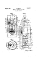
Fig. 1 is a longitudinal section showing the intermitting device rigidly attached to the lower end of a gas induction pipe and resting on an annular projection or shoulder within the fluid eduction pipe;
Fig. 2 is a cross section on line 2-2 of Fig. 1;
Fig. 3 is an section, of a certain portion of the regulating device of Fig. 1, the view being taken from the line 33 of Fig. 1; and
Fig. & is a longitudinal section of a modification wherein the intermitting devicev is attached to the flow tubing.
The form of device shown in Figs. 1, 2 and 3 is carried on the lower end of a gas induction tube A, which is lowered into the casing or fluid eduction tube B, the latter having an annular shoulder 1 for support of the regulator. The flow of gas from tube A into tube B takes place through a plurality of nozzles 2 controlled by rotary gas-supplying valves 3- adapted to be actuated through the medium of pin and slot connected levers 4 by a rod 5 which passes from the lower end of a pipe A through the center of a spider 6 and through a stutfing box 7 carried by the spider on its lower side. The stufiing. box is inturn provided with a small sylphon bellows 8 through which also the rod 5 passes and to which said rod is welded to form a tightoint. The spider 6 includes an annular shoulder which engages the supporting shoulder 1, a suitable washer being used if necessary to more effectively seat the device. Said spider 6 carries on its under side below the supporting shoulder 1 a housing9 which encloses the actuating elements of the regulator. 7
A vertical rib 23 welded or cast on the side of the housing 9 has a drilled hole or duct 24: communicating with the sylphon bellows 13 as at 25 and with a three-way regulating valve 27 located in a chamber 26 on the top of the housing 9. Said valve 27 is adapted to discharge into the annular space 16 by way of an outlet 28 provided with a check-valve 29, and into the gas induction pipe A througha duct 30 drilled in the wall of the chamber 26. Lever 31 of the three-way valve 27 is pin and slot connected to a rod 32 connected with a sylphon bellows 33 within said chamber 26, the rod 32 freely passing through a partition wall 33a. A spring 34 placed between said sylphon bellows and the partition wall 33a tends to collapse the bellows 33. A. nipple 35 connects the bellows with a piezometer ring 36 which is located in the annular space 16 and opens into the same through a plurality of ports 37.
The function of the device shown in Figs. 1, 2 and 3 is as follows:
Assuming that the device has been lowered into the well casing B and that the annular space 16 contains a certain volume of oil which has been forced thereinto by the natural formation pressure, the static pressure of thisoilistransmittedthmughihgmnings 37 of the piezo'meter ring 36 and througlithe nipple 35 into the sylphon bellows 33, thus expanding the latter and pushing the rod 32 outwardly against the action of the spring 3 1. The pressuresexerted on both faces of the valve 10 are in equilibrium because the natural formation pressure against the lower face of said valve 10 is counter-balanced by the static pressure of the oil in the upper space 16. The outward movement of rod 32 operates the lever 31 of the three-way regulating valve 27 to cutoff passage of gas under pressure from the gas induction pipe A through the duct 30 into the duct 24. At the same time, the three-way valve 27 permits any gas pressure in the through said duct 24 and outlet 28 past check valwe 29 which opens outwardly, and to dissipate into the annular space 16, the gas pressure remaining in the bellows 13 being thus substantially equal to the static pressure of the oil in the annular space 16. The bellows 13 is thus collapsed under the action of the sylphon bellows 13 to pass This spring 21 and the weight of the parts attached to the rod 5. The rod5 istherefore moved downward, the valve 10 is closed upon its seat 11, thus preventing the further entrance of oil from the space 15 into the annular space 16.
At the same time, the upper end of rod 5 operates the levers 4 to open the rotary gas-supply valves 3 in the nozzles 2, thereby introducing gas under pressure from the gas induction pipe A under the head of oil in the annular space 16. Due to the fact that the specific weight of gas is considerably lower than that of the oil, the introduction of gas into the fluid eduction pipe B causes a lowering of the static pressure in the latter as soon as ejection of oil from the top of eduction pipe B commences. This in turn causes a slow collapse of the sylphon bellows 33 and an inward movement of rod 32 attached thereto. At a predetermined pressure, which occurs when a suiiicient volume of oil has been ejected from the fluid eduction pipe B, the three-way valve 27 is caused, by the collapse of bellows 33 and a corresponding movement of rod 32, to cut oil communication between the duct 24 and outlet 28, and to permit the introduction of gas under pressure from the gas induction pipe A through the ducts 30 and 24 into the sylphon bellows 13. The latter is thus expanded against the action of the spring 21, thereby-raising the rod 5, unseating the valve 10 and closing the rotary valves 3. prevents the further introduction of gas under pressure into the fluid eduction pipe B, permits the inflow of oil from the space 15 through the perforations 14, around the valve 10 and into the annular space 16, and at the same time causes a rise in the static pressure in the latter space, thus repeating the cycle of operation. If, on first lowering of the device into the well, the pressure under bellows 13 is lower than the head in the annular space 16 (forexample, if it is atmospheric), the valve 27 will not open and the spring 21 will hold bellows 13 in a collapsed position, and, also due to the fact that the pressures on either side of valve 10 are balanced, the valve 10 will remain closed. The functioning of the device is the same as described above. After the device has started functioning and the well has begun flowing, thefluid eduction pipe B will contain regulated slugs of oil alternating with predetermined volumes of gas, and the piezometer ring 36 will be constantly responsive to changes in static head exerted by varying quantities of slugs of oil and gas in said fluid eduction pipe B. From the above it is obvious that, since the actuation of the valve 10 and rotary valves 3 depends on the magnitude of the outward and inward movement of the sylphon bellows 33, it is possible to obtain alternate and predetermined slugs or volumes of gas and oil in the annular space 16, and that by regulating said bellows 33 or the tension of the spring 34 abutting against it the fiow of gas and oil can be. initiated so that the head of oil andgas in thesfluid eduction pipe B shall fluctuate between predetermined limits of pressure.
In the modification of Fig. 4, the intermitting or slug-producing device is assembled on the lower end of a fluid eduction or flow tube, thus obviating the necessity of using an extra string of pipes or a liner in the well, either one of which in some instances might be necessary with the device shown in Figs. 1 to 3 in order to provide the shoulder 3 on which to support the device. As shown in Fig.4, an eduction tubing 41 provided with a plug 42 at its bottom is lowered into the well casing B to which the gas under pressure is to be applied in this case. A baffle plate 43 is welded in said tubing at a short distance from the plug 42', thus producing a compartment 12 for the movement of a piston 44 located therein and provided with packing rings 45 toprevent the escape of gas from the lower part of the compartment into its upper part. A spring 21 corresponding to spring 21 of the other form is placed between the plate 43 and piston 44, and a rod 5' rigidly connected to the piston 44 passes through a. stuffing box 46 in the baifle plate 43 and extends upwardly. A plate valve 10 rigidly attached to the rod 5' cooperates with its seat 11 on the inner wall of the tubing 41 to control inflow of oil. Between the seat 11' and the chamber 12', the tubing 41 is perforated at 14 to permit the'entrance of oil from the lower portion of the casing B into the tubing 41. The upper end of the rod 5 is hinge-connected to levers 4 of rotary valves 3 placed in pipes 47 which lead gas under pressure to the distributing noz-- zle 2 and thence into the interior of the tubing 41.
As in the other form, a piezometer ring 36 is used, this being placed around the tubing 41 and communicating at 48 with the interior of said tubing by means of nipples 49. Said piezometer is also connected by a nipple 35 with the interior of a sylphon bellows 33 placed in a' chamber 26 on the side.
the compartment 12 below the piston 44, and I with a pipe 58 provided with a check-valve 29 opening at 60 into, the tubing 41. It is, of course, clear to those skilled in the art that a sylphon bellows may be used in the compartment 12 instead of the piston 44 and packing ring 45, said bellows, by means of the pressure exerted therein, actuating valve 10 and the rotary valves 3.
As is obvious from the above disclosure and from the functioning of the device shown in Figs. 1 to 3, a rise in the static pressure in the tubing 41 will cause the passage of gas under pressure from the compartment 12 into the tubing 41 through the pipes 56 and 58 and through the three-way valve 27, thus allowing the spring 34' and the weight of the parts on rod 5" to move the piston 44 downwardly and cause the closure of the valve 10 and the opening of the rotary valves 3. The entrance of gas into the tubing 41 under the slugs of oil therein will eject a portion of the oil from said tubing and will thus gradually decrease the static pressure therein. When a predetermined drop in said pressure has occurred, which as stated above is due to the eiection of a certain volume of oil from the fluid eduction pipe, the threeway valve 27 will be moved by the bellows 33, so as to permit the entrance of gas under pressure through pipes 55 and 56 into the compartment 12. Pipe 55 should extend beyond the normal level of the fluid in the well to ensure that it be always in the gas space. The entrance of gas under pressure into compartment 12" will move piston 44 and rod 5 upwardly, will close the rotary valves 3', and will open the valve 10" to permit the entrance of a new slug of oil into the tubing. The device of this form will operate efliciently without the use of a packer to separate the oil accumulation chamber and the gas chamber. However, if desired, a packer may be set between tube 41 and casing B at a point intermediate the valve seat 11 and the nozzles 47. In using this device without a packer the first step will be the discharge of the excess oil by the gas to reduce the oil level to normal operating level as is onventional in all gas-lift operations.
It is clear that the function of the device is based only on the fluctuations of the statichead in the fluid eduction pipe or tubing, irrespective of the pressure variations in the gas induction pipe or the rate of inflow of fluid into the well; that this device may be designed to fluctuate within any desired limits of the static pressure in the fluid eduction pipe; and that the mechanism may be regulated so as to permit predetermined and regulated slugs or volumes of oil and gas to be alternately introduced into the fluid eduction pipe and be raised therethrough in the form of slugs to the surface.
It is obvious that the regulating devices comprising the sylphon bellows 33 and 33' andthe regulating valves 27 and 27 may be made highly sensitive in order that the actuation of the gas valves 8 and the oil valve 10 will be rapid thereby causing introduction of oil in the form of small volumes to be passed up through the flow tube B under the influence of small volumes of gas which serve to separate the oil slugs. This will result in a substantially constant static head in' the flow tube and in this manner a substantially constant gas-oil ratio in the flow tube will be maintained. On the other hand the regulating device may be made sensitive only to wide difference of static head in the flow tube B, so that, although gas and oil introduction is still regulated by head pressure, the oil will take the form of relatively long columns separated by relatively large volumes of gas, and the regulator will function only by discharge of one of said long columns from the top and the accumulation of a similar column in the bottom of the flow tube.
The above disclosures are to be considered not as limiting, but as merely illustrative, and many variations which will be apparent to those skilled in the art may be made within the scope of the following claims.
I claim:
1. In a method for producing an intermittent flow from a well, the step of alternately introducing predetermined and regulated volumes of gas and of fluid into the eduction pipe of said well.
2. In a method for producing an intermittent flow from an eduction pipe of a well, the step of alternately introducing a liquid and a gas into said eduction pipe wholly in accordance with changes in static pressure in the same and independently of applied gas and oil pressures.
3. Ina method for producing an intermittent flow from an eduction pipe of a well, the step of introducing regulated slugs of liquid into said eduction pipe, and the step of introducing regulated volumes of gas into the same pipe, said two steps functioning alternately in accordance with changes in static pressure within said eduction pipe and independently of applied gas and oil pressures.
4. A method for flowing wells comprising applying gas under pressure to produce periodical discharge of slugs of liquid, and regulating the periods of discharge wholly in accordance with changes in static head of the liquid and independently of applied gas and oil pressures.
5. In a method for producing controlled flow of fluid from a fluid eduction pipe of a well, the step of periodically introducing gas into the eduction pipe and governing said introduction wholly by the static pressure in said eduction pipe and independently of applied gas and oil pressures.
6. A method comprising flowing a fluid from an eduction pipe of a well by means of gas under pressure, and intermittently introducing said gas wholly in accordance with variations in static pressure of the fluid and independently of applied gas and oil pressures.
7. A gas-1ift method for the recovery of liquids from wells comprising introducing gas under pressure into the well to elevate liquid therefrom through an eduction pipe, and controlling the introduction of liquid into said eduction pipe in accordance with variations of the static head therein and independently of applied gas and oil pressures.
8. A method for flowing a well by gas-lift comprising introducing a gas under pressure into a well for elevation of a liquid therefrom through an eduction pipe and controlling the introduction of liquid into said pipe in slugs separated by volumes of gas, said control being in accordance with variations in static head in the tube and independently of applied gas and oil pressures.
9. A gas-lift method for the recovery of liquid from a well comprising introducing gas under pressure into the well to elevate liquid through an eduction pipe, and regulating the introduction of liquid into said eduction pipe to maintain a substantially constant static pressure in said pipe.
10. A gas-lift method for the recovery of oil from wells comprising introducing gas under pressure into a well to elevate the oil through an eduction pipe, and controlling the introduction of oil and gas into said eduction pipe to maintain a substantially constant ratio of gas to oil.
11. In a method for producing an intermittent flow from an eduction pipe of a well, the step of alternately introducing gas and oil intothe pipe, both the gas introduction and the oil introduction occurring in proportion to changes in static pressure in said eduction 1 e. P I2. In a method for producing an intermittent flow from an eduction pipe of a well, the step of introducing regulated volumes of gas into said pipe when static pressure therein reaches a predetermined upper limit, and the step of introducing regulated volumes of oil into said pipe when the static pressure therein reaches a predetermined lower limit.
13. A device for flowing wells and the like comprising a flow tube, means for intermittently introducing gas under pressure into the flow tube, and means sensitive to changes in static head of the liquid and connected to control the gas introducing means and independently of applied gas'and oil pressures.
14:. In combination with a fluid eduction pipeof a well, means associated with the eduction pipe to intermittently introduce gas thereinto, means associated with the said eduction pipe to intermittently introduce oil thereinto and means wholly responsive to static pressure in said fluid eduction pipe to operate said two means alternately.
15. In combination with a fluid eduction pipe of a well, means associated with said pipe to alternately introduce ,oil and gas thereinto, and means to control said introducing means for introduction of predetermined and regulatedslugs -of'oil and gas into said pipe wholly in accordance with changes in static head in said fluid eduction pipe and independently of applied gas and oilpressures.
16. In combination with a fluid eduction pipe, means associated therewith and responsive to fluctuations in static pressure in said fluid eduction pipe, and means operatively connected with and controlled by the first means to alternately introduce gas and liquid into said pipe in accordance with fluctuations in said static pressure independently of applied gas pressure.
17. In combination with 'a flow tubing of a well, means sensitive to static head changes, and means controlled thereby and located adjacent the lower end of the tube to alternately introduce into said tubing predetermined and regulated slugs of oil and gas in accordance with changes in static head in said flow tubing independently of applied gas pressure.
18. In combination with a flow tubing of a well, means communicating with the lower portion of the flow tubing and responsive to fluctuations in static pressure within the same, and means operatively connected with the first means to alternately introduce gas and liquid from the well casing into said flow tubing in accordance with the changes in static pressure as transmitted by the first mentioned means independently of applied gas pressure.
19. In combination with a flow tubing of a well, means located on the lower portion of said tubing and responsive to fluctuations in static pressure in the same, means operatively connected with said first means to intermittently introduce gas into said flow tubing,
and means operatively connected with the first means to intermittently introduce oil into the tubing, said last two means operating to alternately introduce gas and oil into said tubing in accordance w1th the changes in the static pressure as transmitted by the first mentioned means and independently of applied gas pressure.
20. In combination with a gas induction pipe and a fluid eduction pipe communicating with each other, a piezometer ring opening into the lower portion of the fluid eduction pipe and responsive to changes in static pressure within the same, a conduit opening from the gas induction pipe into the fluid eduction pipe, a valve for said conduit, and means operatively connected with the piezometer ring and the valve to actuate the valve in accordance with changes in the static pressure.
21. In combination with a gas induction pipe and a fluid eduction pipe communicating with each other, a piezometer ring opening into the fluid eduction pipe, a bellows repermitting motion of the rod with respectto sponsive to static pressure in said piezometer the housing. A
ring, a conduit opening from the gas induc- Signed at Los Angeles, in the county of tion pipe into the fluid eduction pipe, a valve Los Angeles and State of California, this on said conduit, and a connection between 15th day of May, A. D. 1930.
said bellows andgthe valve to actuate said valve in accordance with the movement of said bellows.
22. A flow device for oil wells comprising a gas induction pipe and a fluid eduction pipe arranged for communication with each other, a conduit for supplying gas from the induction pipe to the eduction pipe, a gas supply valve in said conduit, a pressure responsive device connected to actuate said valve, a pressure sensitive device actuable by variations in static head in the well, a pressure line leading from the induction pipe to the pressure responsive device, and a regulating valve in said line actuable by the pressure sensitive device to pass gas pressure to the pressure responsive device for actuation of the gas valve.-
28. A construction according to claim 22 wherein an exhausting outlet is provided for the gas line to the pressure responsive device, said outlet being controlled by the regulating valve, whereby the application of pressure to said pressure responsive device moves the latter in one direction and exhaust of pressure from said line through said outlet permits said responsive device to move in the opposite direction.
24. A construction according to claim 22, wherein the pressure sensitive device is connected with the eduction pipe for actuation by variations in static head within said eduction tube.
25. A flow device for oil wells compris- I ing a gas induction tube leading to a source of oil supply, a fluid eduction tube leading from said supply, a conduit for leading gas from the induction tube to the eduction tube, a. gas supply valve in said conduit, an oil valve for controlling flow of oil into the eduction tube, a bellows, a connection between said bellows and said oil and gas valves, a gas line connecting the induction tube and the bellows, a regulating valve in said line, a second bellows to actuate said regulating valve, and a piezometer ring communicating with the eduction tube and connected with said second bellows for applying a controlling pressure to the latter.
26. In a well flowing device a housing, a sylphon bellows mounted in said housing, means to transmit pressure changes from the well to said bellows, an actuating rod connected with said bellows and projecting from said housing, a valve associated with said housing to be actuated by said rod, and a second sylphon bellows of relatively small dimensions through which said rod projects, said second bellows having a tight joint with said housing and with said rod to act as a seal PHILIP SUBKOW.
Priority Applications (1)
| Application Number | Priority Date | Filing Date | Title |
|---|---|---|---|
| US455913A US1856891A (en) | 1930-05-26 | 1930-05-26 | Method and apparatus for gas lift |
Applications Claiming Priority (1)
| Application Number | Priority Date | Filing Date | Title |
|---|---|---|---|
| US455913A US1856891A (en) | 1930-05-26 | 1930-05-26 | Method and apparatus for gas lift |
Publications (1)
| Publication Number | Publication Date |
|---|---|
| US1856891A true US1856891A (en) | 1932-05-03 |
Family
ID=23810734
Family Applications (1)
| Application Number | Title | Priority Date | Filing Date |
|---|---|---|---|
| US455913A Expired - Lifetime US1856891A (en) | 1930-05-26 | 1930-05-26 | Method and apparatus for gas lift |
Country Status (1)
| Country | Link |
|---|---|
| US (1) | US1856891A (en) |
-
1930
- 1930-05-26 US US455913A patent/US1856891A/en not_active Expired - Lifetime
Similar Documents
| Publication | Publication Date | Title |
|---|---|---|
| US2698054A (en) | Method of and apparatus for lowering pipe within a well bore | |
| US2385316A (en) | Well flow device | |
| US2391605A (en) | Well flow device | |
| US2061865A (en) | Water eductor and method | |
| US2870843A (en) | Apparatus for control of flow through the annulus of a dual-zone well | |
| US3973586A (en) | Velocity-tubing pressure actuated subsurface safety valve | |
| US2725014A (en) | System and apparatus for flowing wells | |
| US2446680A (en) | Well flow device | |
| US2642889A (en) | Gas lift valve | |
| US2349164A (en) | Bottom hole intermitter for pumping wells | |
| US2680408A (en) | Means for dually completing oil wells | |
| US1723682A (en) | Well pump | |
| US2142484A (en) | Gas-lift pump | |
| US2179226A (en) | Well flowing valve | |
| US2499357A (en) | Two-zone pumping system with control valve | |
| US3294108A (en) | Gas lift valve | |
| US1856891A (en) | Method and apparatus for gas lift | |
| US2208036A (en) | Well flowing apparatus and method | |
| US3066690A (en) | Well injection and bleed valve | |
| US1993292A (en) | Flow regulator for plunger lift pumps | |
| US2865305A (en) | Gas lift apparatus | |
| US1000583A (en) | Packer for operating gas, water, and oil wells. | |
| US2875775A (en) | Gas lift valve | |
| US2213372A (en) | Apparatus for producing oil from subsurface deposits | |
| US2296833A (en) | Input air or gas control valve for cased wells |