US1856877A - Receptacle - Google Patents
Receptacle Download PDFInfo
- Publication number
- US1856877A US1856877A US565106A US56510631A US1856877A US 1856877 A US1856877 A US 1856877A US 565106 A US565106 A US 565106A US 56510631 A US56510631 A US 56510631A US 1856877 A US1856877 A US 1856877A
- Authority
- US
- United States
- Prior art keywords
- handle
- cover
- receptacle
- rim
- slot
- Prior art date
- Legal status (The legal status is an assumption and is not a legal conclusion. Google has not performed a legal analysis and makes no representation as to the accuracy of the status listed.)
- Expired - Lifetime
Links
Images

Classifications
-
- B—PERFORMING OPERATIONS; TRANSPORTING
- B65—CONVEYING; PACKING; STORING; HANDLING THIN OR FILAMENTARY MATERIAL
- B65F—GATHERING OR REMOVAL OF DOMESTIC OR LIKE REFUSE
- B65F1/00—Refuse receptacles; Accessories therefor
- B65F1/14—Other constructional features; Accessories
- B65F1/16—Lids or covers
- B65F1/1615—Lids or covers with means for locking, fastening or permanently closing thereof
-
- Y—GENERAL TAGGING OF NEW TECHNOLOGICAL DEVELOPMENTS; GENERAL TAGGING OF CROSS-SECTIONAL TECHNOLOGIES SPANNING OVER SEVERAL SECTIONS OF THE IPC; TECHNICAL SUBJECTS COVERED BY FORMER USPC CROSS-REFERENCE ART COLLECTIONS [XRACs] AND DIGESTS
- Y10—TECHNICAL SUBJECTS COVERED BY FORMER USPC
- Y10T—TECHNICAL SUBJECTS COVERED BY FORMER US CLASSIFICATION
- Y10T292/00—Closure fasteners
- Y10T292/08—Bolts
- Y10T292/0894—Spring arm
-
- Y—GENERAL TAGGING OF NEW TECHNOLOGICAL DEVELOPMENTS; GENERAL TAGGING OF CROSS-SECTIONAL TECHNOLOGIES SPANNING OVER SEVERAL SECTIONS OF THE IPC; TECHNICAL SUBJECTS COVERED BY FORMER USPC CROSS-REFERENCE ART COLLECTIONS [XRACs] AND DIGESTS
- Y10—TECHNICAL SUBJECTS COVERED BY FORMER USPC
- Y10T—TECHNICAL SUBJECTS COVERED BY FORMER US CLASSIFICATION
- Y10T292/00—Closure fasteners
- Y10T292/42—Rigid engaging means
- Y10T292/438—Spring-arm catch
Definitions
- This invention relates to receptacles having a removable, self locking cover, the present embodiment of the invention being particularly adapted for use in connection withwhat are commonly known as garbage cans where it is desirable to prevent tilting, lifting, or removal of the cover either by the force of the wind or by animals.
- Qne object of the invention is to construct a receptacle and a removable cover or lid therefor provided with inter-engaging elements, one of which constitutes a'gravity operated handle adapted to lock the cover in position but arranged, when raised relative thereto, to permit, ready removal of the cover.
- Another object of'theinvention is to construct a receptacle and a cover or lid therefor having between them self locking elements of relatively simple construction.
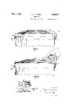
- FIG. 1 is a side elevation of a receptacle embodying my invention.
- Fig. 2 is a plan view, with parts broken away.
- Fig. 3 is a fragmentary section on the line 3-3 of F ig.'2, showing the position of the cover when attempt ismade to elevate it.
- Fig. 4 is a view similar to Fig. 3 showing the position of the handle when raised preparatory to removing-the cover in the usual manner.
- Fig. 5 is a fragmentary section on the line 5-5 of Fig. 2, enlarged.
- Fig. 6 is a fragmentary section (enlarged) on the line 3-3 of Fig. 2.
- Fig. 7 is a. view similar to Fig. 5, but showing a handle having a slightly different form of construction.
- Fig. 8 is a fragmentary view showing a different form of inter-engaging device.
- Fig. 9 is a section on the line 99 of, Fig. 8.
- the receptacle 1 may be of any suitable and convenient form, said receptacle, in the present instance, comprising the usual cylindrical receptacle or container body and provided around its upper marginal edges with an outwardly extending projection 1a, said projection, in the present instance, comprising the usual outwardly extending beaded I rim. 1 indicates a bail or handle.
- the lid or cover 2 may likewise be of any suitable and convenient form, being provided with a depending rim 2a, adapted to fit over the top of the receptacle'or container-jand preferably provided around its-lower or terminating edge with a beaded portion 2?).
- one side of the rim 2a is provided internallywith a device 3 disposed in opposed relation to ,the side wall or body of the receptaclel and arranged to engage the bead 1a when attempt is made to raise the cover 2 (see Fig. 3), ex-
- the device 3 preferably comprises aresilient, flat metal strip, the free end-portion of which normally flexes inwardly, so that when the cover 2 is positioned it tends to move or slide the cover laterally on the beadla to more effectively insure engagement of the handle with the bead 1a, as later set forth.
- the device 3 comprises a horizontally disposed resilient metal strip 3a having its intermediate portion suitably riveted to the inner wall of the rim 2a,. its end portions being free and normally engaging the side wall or body of the receptacle 1, when the cover is on the receptacle 1, as most clearly shown in Figs. 1 and ,2.
- the device is shown as comprising a vertically disposedv resilient metal strip 3?), riveted at its lower end to the internal wall of the rim 2a and extending upwardly, its upper end being free and normally engaging the side wall of the receptacle 1.
- the handle 4 consists of a section of flat strip metal, pivotally and slidably connected at its inner end to the exterior surface of the cover 2, as shown at 4, its outer portion being turned downwardly and inwardly, as shown. at 5.
- the inwardly extending portion 5of the handle t extends through an elongated vertical slot 6 formed in the adjacent portion of the rim 2a and its free end terminates in an up-turned lip or latch 7.
- ⁇ Vhen the handle 4 is in its normal or gravitated position, as shown in Figs.
- the lip or latch 7 is operatively related to the bead 1a, being below and within its periphery, so as to inter-engage therewith when attempt is made to tilt, elevate or raise the cover 2, as shown in dotted and full lines in Fig. 3.
- the handle is grasped, in the operation of removing the cover, it is first raised and slightly slid outwardly relative to the cover, the effect of which is to swing it outwardly and upwardly as shown in dotted lines in Fig. 4, such movement being permitted by the pivotal, slidable connection 1 between the handle and cover.
- the end portion 5 moves through the slot 6 in an upward, outward direction until the lip 7 engages the upper.
- the cover may be further raised bodily and removed without interference or engagement of the device 3 at the opposite side of the cover with the adjacent portion of the rim 1a.
- That portion of the rim 2a, in which the slot 6 is formed, is provided with an outwardly extending bulge 8, and the upper end of the slot 6 terminates approximately centrally of the bulge 8, so that when the latch 7 is stopped by the upper end wall of the slot the latch is disposed at the outermost position provided by the bulge.
- the outer portion of the handle l is preferably inclined or curved downwardly and inwardly, so that when upward pressure isapplied to the cover or rim 2a, the bottom wall of the slot 6 will engage such portion and through it maintain the latch 7 in operative relation to the bead 1a while swinging-the handle 4 upwardly.
- connection 4' preferably comprises a stepped stud or rivet 9 having its inner end fixedly mountedin the cover 2 and an elongated slot 10 formed in the inner end'portion of the handle.
- the body of the rivet 9 extends loosely through the slot 10 and is provided with a head 11 spaced from the top surface of the cover 2 so that the handle is free to slide endwise and also pivot or swing on the body of the rivet, the head 11 serving to maintain the handle in connected relation to the body of the rivet.
- the interlocking means comprise the following: 13, 13a, indicate two vertical r which extend through and are slidable in the slots 13, 13a, respectively, one bar (for example, the bar 141)) being slitted transversely to permit of assembly.
- the slot 6 formed in the rim 2a is relatively narrow and the handle portion 5 is cut away on one edge to form a bar 15 whichprojects through and slides in the slot 6'.
- the latch 7' extends laterally relative to the bar 15, it lies behind the adjacent portion of the rim 2a and thus prevents the end portion 5 from being withdrawn or the latch 7 moved to an inoperative position.
- I provide afreely movably handle which is operated upwardly and outwardly to release the cover and when released it gravitates into operative relation to the adjacent portion of the bead 1a so that the cover becomes automatically locked to the receptacle; also, that I provide pivotal and slidable connections between the opposite ends of the handle 4 and cover, whereby the handle 4 is guided in its movement in either direca direction substantially axially of the receptacle or when the upward pressure on the cover is applied at one edge thereof intermediate the device 3 and handle 4.
- the device 3 By making the device 3 of resilient metal, it tends to maintain that side of the rim 21; carrying the handle 4: in close engagement with the bead 1a. This permits the cover ,2 to be made large enough to readily fit the rim 1a so that iii may be easily removed and replaced.
- connection -for the-cover at that side thereof opposite the handle 4 may be in the form of a typical hinge instead of a detachable connection or one that is eifected by engagement or dis-' engagement such as herein shown.
- a container construction comprising a receptacle having a projection, a cover hav ing a depending rim formed a handle having its inner end portion pivotally and slidably connected to said cover to move relative thereto outwardly substantially in the plane of suchportion, the outer end portion of said handle being bent down wardly and inwardly and movably extending through said opening, a latch on the outer with an opening,
- a container construction comprising a receptacle having a marginal projection, a cover for said receptacle having a depending rim, said rim being 'formed with a slot disposed below said projection when said cover is in position, a handle having its inner end portion pivotally and slidably connected to said cover to move relative'thereto outwardly substantially in the plane of such portion, the outer end portion of said handle extending through and movable in saidslot, to permit movement of the handle toward and from said cover, a latch on the outer end of said handle disposed below and within said projection when the handle is in its lower position and arranged to clear said projection whenthe handle is raised relative to said cover, and means between the outer end portion of said handle and said rim for preventing withdrawal of said end portion through said slot.
- a container construction comprising a receptacle having a marginal projection, a cover for said receptacle having a depending rim, saicl'rim being formed with a slot, a handle having its inner end portion pivotally and slidably connected to said cover to move relative thereto outwardly substantially in the plane of-such portion, the outer end portion of said handle extending through and movable in said slot to permit movement of the handle toward and from said cover, a latch on the outer end of said handle disposed below and within said projection when the handle is in its lower position and arranged to clear said projection when the handle is,
- a container comprising a receptacle having a head around its open end and a cover having a rim fitting over theopen end of said receptacle and formed with an opening, a handle having a flat inner end portion formed with a longitudinally extending slot, a'headed pin 'on saidcover extending through said slot and arranged to slidably and pivotally connect said handle to said cover, the outer end portion of said handle extending through said opening for movement vertically therein, a latch on the outer free end of said han- J dle arranged to engage said bead when force is applied to the cover to remove it but arranged to' free the said head when the handle is raised relative to said cover, and means between said handle and rim for connecting the handle thereto when the handle is raised relative to the.
- a container construction comprising a receptacle having a marginal projection, a removable cover having a depending rim formed with a slot, and devices on said cover adapted to engage said projection and prevent removal of the cover when force is applied thereto to raise it, one device comprising a handle pivotally mounted at its inner end on said cover, its outer end portion extending through said slot for removable enwhen raised being arranged to clear said pro ect1on, and the other (levlce disposed on the inner side of said rim and consisting of ahorizontally disposed flat spring fixed face to face to said rim intermediate its ends and having its opposite ends curved inwardly and normally engaging the receptacle side wall below said projection when the cover is inposition. .v
Description
E. O. LOEBER May 3, 1932.
RECEPTACLE Filed Sept. 25, 1931 2 Sheets-Sheet H INVENTOR BY (0' i 1 b Mfl.om
ATTORNEY.
E. O. LOEBER May 3, 1932.
ATTORNEY.
Patented May' 3, 1 932 EDGAR O. I JOEBER, OF CLEVELAND, OHIO RECEPTACLE Application filed September 25, 1931. Serial No. 565,106.
This invention relates to receptacles having a removable, self locking cover, the present embodiment of the invention being particularly adapted for use in connection withwhat are commonly known as garbage cans where it is desirable to prevent tilting, lifting, or removal of the cover either by the force of the wind or by animals.
Qne object of the invention is to construct a receptacle and a removable cover or lid therefor provided with inter-engaging elements, one of which constitutes a'gravity operated handle adapted to lock the cover in position but arranged, when raised relative thereto, to permit, ready removal of the cover.
Another object of'theinvention is to construct a receptacle and a cover or lid therefor having between them self locking elements of relatively simple construction.
Other objects of the invention will be apparent to those skilled in the art to which my invention relates from the following descrip tion taken in connection with the accompanying drawings, wherein Fig. 1 is a side elevation of a receptacle embodying my invention.
Fig. 2 is a plan view, with parts broken away.
Fig. 3 is a fragmentary section on the line 3-3 of F ig.'2, showing the position of the cover when attempt ismade to elevate it.
Fig. 4 is a view similar to Fig. 3 showing the position of the handle when raised preparatory to removing-the cover in the usual manner.
Fig. 5 is a fragmentary section on the line 5-5 of Fig. 2, enlarged.
Fig. 6 is a fragmentary section (enlarged) on the line 3-3 of Fig. 2.
Fig. 7 is a. view similar to Fig. 5, but showing a handle having a slightly different form of construction.
Fig. 8 is a fragmentary view showing a different form of inter-engaging device.
Fig. 9 is a section on the line 99 of, Fig. 8.
The receptacle 1, may be of any suitable and convenient form, said receptacle, in the present instance, comprising the usual cylindrical receptacle or container body and provided around its upper marginal edges with an outwardly extending projection 1a, said projection, in the present instance, comprising the usual outwardly extending beaded I rim. 1 indicates a bail or handle.
The lid or cover 2 may likewise be of any suitable and convenient form, being provided with a depending rim 2a, adapted to fit over the top of the receptacle'or container-jand preferably provided around its-lower or terminating edge with a beaded portion 2?).
As a means of initially mounting and securing one side of the cover 2, to the upper marginal edges of the receptacle 1, one side of the rim 2a, is provided internallywith a device 3 disposed in opposed relation to ,the side wall or body of the receptaclel and arranged to engage the bead 1a when attempt is made to raise the cover 2 (see Fig. 3), ex-
. cept when a handle 4, to be later referred to,
is first raised, as shown in Fig. 3. The device 3 preferably comprises aresilient, flat metal strip, the free end-portion of which normally flexes inwardly, so that when the cover 2 is positioned it tends to move or slide the cover laterally on the beadla to more effectively insure engagement of the handle with the bead 1a, as later set forth. In the'form of construction shown in Figs. 1, 2 and3, the device 3 comprises a horizontally disposed resilient metal strip 3a having its intermediate portion suitably riveted to the inner wall of the rim 2a,. its end portions being free and normally engaging the side wall or body of the receptacle 1, when the cover is on the receptacle 1, as most clearly shown in Figs. 1 and ,2. In Figs. 8 and 9, the device is shown as comprising a vertically disposedv resilient metal strip 3?), riveted at its lower end to the internal wall of the rim 2a and extending upwardly, its upper end being free and normally engaging the side wall of the receptacle 1. v
The handle 4 consists of a section of flat strip metal, pivotally and slidably connected at its inner end to the exterior surface of the cover 2, as shown at 4, its outer portion being turned downwardly and inwardly, as shown. at 5. The inwardly extending portion 5of the handle t extends through an elongated vertical slot 6 formed in the adjacent portion of the rim 2a and its free end terminates in an up-turned lip or latch 7. \Vhen the handle 4 is in its normal or gravitated position, as shown in Figs. 1, 2 and 4, the lip or latch 7 is operatively related to the bead 1a, being below and within its periphery, so as to inter-engage therewith when attempt is made to tilt, elevate or raise the cover 2, as shown in dotted and full lines in Fig. 3. However, when the handle is grasped, in the operation of removing the cover, it is first raised and slightly slid outwardly relative to the cover, the effect of which is to swing it outwardly and upwardly as shown in dotted lines in Fig. 4, such movement being permitted by the pivotal, slidable connection 1 between the handle and cover. In such operation, the end portion 5 moves through the slot 6 in an upward, outward direction until the lip 7 engages the upper. end wall of the slot 6, such direction of movement serving to so position the latch 7 that in the continued raising movement the lip 7 clears the bead 1a and through its engagement with the slot end wall the cover is carried-upwardly I with the handle. After the latch 7 passes the bead 1a, the cover may be further raised bodily and removed without interference or engagement of the device 3 at the opposite side of the cover with the adjacent portion of the rim 1a. To insure clearance of the latch 7 before it engages the upper end wall of the slot 6, after the handle 4 is raised relative to the cover, that portion of the rim 2a, in which the slot 6 is formed, is provided with an outwardly extending bulge 8, and the upper end of the slot 6 terminates approximately centrally of the bulge 8, so that when the latch 7 is stopped by the upper end wall of the slot the latch is disposed at the outermost position provided by the bulge.
The outer portion of the handle lis preferably inclined or curved downwardly and inwardly, so that when upward pressure isapplied to the cover or rim 2a, the bottom wall of the slot 6 will engage such portion and through it maintain the latch 7 in operative relation to the bead 1a while swinging-the handle 4 upwardly.
The connection 4' preferably comprises a stepped stud or rivet 9 having its inner end fixedly mountedin the cover 2 and an elongated slot 10 formed in the inner end'portion of the handle. The body of the rivet 9 extends loosely through the slot 10 and is provided with a head 11 spaced from the top surface of the cover 2 so that the handle is free to slide endwise and also pivot or swing on the body of the rivet, the head 11 serving to maintain the handle in connected relation to the body of the rivet.
I preferably provide interlocking means between the end portion 5 of the handle 4 and the rim 2a so that the latch 7 cannot be der the handle inoperative to engage the bead 1a and non-cooperative with the device 3. In the form of construction shown in Figs. 1 to 5, the interlocking means comprise the following: 13, 13a, indicate two vertical r which extend through and are slidable in the slots 13, 13a, respectively, one bar (for example, the bar 141)) being slitted transversely to permit of assembly. As the latch 7 extends across the wall 136 and is connected to the bars 14a, 14?), it will be seen that the end portion 5 and latch 7 is operatively connected to the rim 2a and cannot be distorted and bent into ,.an inoperative or ineffective position except by the use of undue force.
In the form of interlocking means shown in Fig. 7, the slot 6 formed in the rim 2a is relatively narrow and the handle portion 5 is cut away on one edge to form a bar 15 whichprojects through and slides in the slot 6'. As the latch 7' extends laterally relative to the bar 15, it lies behind the adjacent portion of the rim 2a and thus prevents the end portion 5 from being withdrawn or the latch 7 moved to an inoperative position.
From theforegoing description it will be noted that I provide afreely movably handle which is operated upwardly and outwardly to release the cover and when released it gravitates into operative relation to the adjacent portion of the bead 1a so that the cover becomes automatically locked to the receptacle; also, that I provide pivotal and slidable connections between the opposite ends of the handle 4 and cover, whereby the handle 4 is guided in its movement in either direca direction substantially axially of the receptacle or when the upward pressure on the cover is applied at one edge thereof intermediate the device 3 and handle 4.
By making the device 3 of resilient metal, it tends to maintain that side of the rim 21; carrying the handle 4: in close engagement with the bead 1a. This permits the cover ,2 to be made large enough to readily fit the rim 1a so that iii may be easily removed and replaced.
It will be noted that after the handle 4 is initially raised to release the latch 7 from the bead 1a, the cover 2 may be swung about an axis disposed adjacent the diametrical opposite portion of the receptacle 1. From this it will be apparent that the connection -for the-cover at that side thereof opposite the handle 4 may be in the form of a typical hinge instead of a detachable connection or one that is eifected by engagement or dis-' engagement such as herein shown.
To those skilled in the art to which my invention relates, many changes in construction and widely dilfering embodiments and applications of the invention will suggest themselves without departing from the spirit and scope of the invention. My disclosures and the description-herein are purely illustrative and are not intended to be in any sense limiting. t
What I claim is: 1. A container construction comprising a receptacle having a projection, a cover hav ing a depending rim formed a handle having its inner end portion pivotally and slidably connected to said cover to move relative thereto outwardly substantially in the plane of suchportion, the outer end portion of said handle being bent down wardly and inwardly and movably extending through said opening, a latch on the outer with an opening,
end of said handle disposed below and within said projection 'when the handle is in its lower position and arranged to clear said projection when the handle is initially operated to elevate said cover, said handle and move relative thereto outwardly substantial ly in the plane of such portion, the outer end portion of 'said handle extending through and movable in said slot to permitmovement of the handle toward and from said cover,
and a latch on the outer end of said handle disposed below and within said projection when 'the handle is in its lower position and arranged to clear said projection when the handle. is raised relative to said cover said latch extending laterally of said slot and ar-. ranged to engage the rim when the handle is raised to connect the outer end of the handle thereto.
3. A container construction comprising a receptacle having a marginal projection, a cover for said receptacle having a depending rim, said rim being 'formed with a slot disposed below said projection when said cover is in position, a handle having its inner end portion pivotally and slidably connected to said cover to move relative'thereto outwardly substantially in the plane of such portion, the outer end portion of said handle extending through and movable in saidslot, to permit movement of the handle toward and from said cover, a latch on the outer end of said handle disposed below and within said projection when the handle is in its lower position and arranged to clear said projection whenthe handle is raised relative to said cover, and means between the outer end portion of said handle and said rim for preventing withdrawal of said end portion through said slot.
4. A container construction comprising a receptacle having a marginal projection, a cover for said receptacle having a depending rim, saicl'rim being formed with a slot, a handle having its inner end portion pivotally and slidably connected to said cover to move relative thereto outwardly substantially in the plane of-such portion, the outer end portion of said handle extending through and movable in said slot to permit movement of the handle toward and from said cover, a latch on the outer end of said handle disposed below and within said projection when the handle is in its lower position and arranged to clear said projection when the handle is,
raised relative to said cover, and means between the outer end-portion of said handle and said rim for preventing withdrawal of said end portion through. said slot, the outer end portion of the handle extending inwardly and downwardly and arranged to be engaged by the lower end wall'of said slot to maintain said latch in operative position when-force is appliedto the cover to elevate it.
5. A container comprising a receptacle having a head around its open end and a cover having a rim fitting over theopen end of said receptacle and formed with an opening, a handle having a flat inner end portion formed with a longitudinally extending slot, a'headed pin 'on saidcover extending through said slot and arranged to slidably and pivotally connect said handle to said cover, the outer end portion of said handle extending through said opening for movement vertically therein, a latch on the outer free end of said han- J dle arranged to engage said bead when force is applied to the cover to remove it but arranged to' free the said head when the handle is raised relative to said cover, and means between said handle and rim for connecting the handle thereto when the handle is raised relative to the. cover, whereby the cover may be removed. L v v 6. A container construction comprising a receptacle having a marginal projection, a removable cover having a depending rim formed with a slot, and devices on said cover adapted to engage said projection and prevent removal of the cover when force is applied thereto to raise it, one device comprising a handle pivotally mounted at its inner end on said cover, its outer end portion extending through said slot for removable enwhen raised being arranged to clear said pro ect1on, and the other (levlce disposed on the inner side of said rim and consisting of ahorizontally disposed flat spring fixed face to face to said rim intermediate its ends and having its opposite ends curved inwardly and normally engaging the receptacle side wall below said projection when the cover is inposition. .v
In testimony whereof, I have hereunto affixed my signature.'
EDGAR ONLOEBER.
Qagement with said projection, said handle-
Priority Applications (1)
| Application Number | Priority Date | Filing Date | Title |
|---|---|---|---|
| US565106A US1856877A (en) | 1931-09-25 | 1931-09-25 | Receptacle |
Applications Claiming Priority (1)
| Application Number | Priority Date | Filing Date | Title |
|---|---|---|---|
| US565106A US1856877A (en) | 1931-09-25 | 1931-09-25 | Receptacle |
Publications (1)
| Publication Number | Publication Date |
|---|---|
| US1856877A true US1856877A (en) | 1932-05-03 |
Family
ID=24257230
Family Applications (1)
| Application Number | Title | Priority Date | Filing Date |
|---|---|---|---|
| US565106A Expired - Lifetime US1856877A (en) | 1931-09-25 | 1931-09-25 | Receptacle |
Country Status (1)
| Country | Link |
|---|---|
| US (1) | US1856877A (en) |
Cited By (4)
| Publication number | Priority date | Publication date | Assignee | Title |
|---|---|---|---|---|
| US2756084A (en) * | 1953-04-13 | 1956-07-24 | Kenneth D Fraser | Self-locking lid for containers |
| US3059807A (en) * | 1960-03-07 | 1962-10-23 | Edward J Hill | Garbage cans |
| US3104903A (en) * | 1963-09-24 | Latching means for receptacles | ||
| US20140197172A1 (en) * | 2013-01-17 | 2014-07-17 | Francis Magny | Lid securing device and refuse container including same. |
-
1931
- 1931-09-25 US US565106A patent/US1856877A/en not_active Expired - Lifetime
Cited By (4)
| Publication number | Priority date | Publication date | Assignee | Title |
|---|---|---|---|---|
| US3104903A (en) * | 1963-09-24 | Latching means for receptacles | ||
| US2756084A (en) * | 1953-04-13 | 1956-07-24 | Kenneth D Fraser | Self-locking lid for containers |
| US3059807A (en) * | 1960-03-07 | 1962-10-23 | Edward J Hill | Garbage cans |
| US20140197172A1 (en) * | 2013-01-17 | 2014-07-17 | Francis Magny | Lid securing device and refuse container including same. |
Similar Documents
| Publication | Publication Date | Title |
|---|---|---|
| US3307752A (en) | Captive plastic closure for container with integral container handle | |
| US4141461A (en) | Secure bottle with novel cap | |
| US3450297A (en) | Refuse bins | |
| US1028499A (en) | Can with self-closing lid. | |
| US1856877A (en) | Receptacle | |
| US2281251A (en) | Container | |
| US2176306A (en) | Tank construction | |
| US3730380A (en) | Can end with inseparable tear strip and latch means for holding tear strip against can wall | |
| US4534488A (en) | Locking device for garbage can lid | |
| US2323886A (en) | Manhole cover | |
| US2521098A (en) | Can | |
| US3235123A (en) | Wire opener attached by boss to scored can end | |
| EP0011496A1 (en) | Child-resistant closures | |
| US2004852A (en) | Sheet metal container | |
| US2039764A (en) | Receptacle | |
| US2111359A (en) | Receptacle cover | |
| US1961223A (en) | Receptacle cover | |
| US1977641A (en) | Receptacle | |
| US1862730A (en) | Cover lock for pails | |
| US2220319A (en) | Receptacle cover | |
| US1727087A (en) | Lock cover for pails | |
| US2172761A (en) | Receptacle cover | |
| US1765478A (en) | Metal container | |
| US2049373A (en) | Receptacle | |
| US1639093A (en) | Cover indexing device and fastener for cooking utensils |