US1856872A - Automatic pressure retainer for gas lift wells - Google Patents
Automatic pressure retainer for gas lift wells Download PDFInfo
- Publication number
- US1856872A US1856872A US378802A US37880229A US1856872A US 1856872 A US1856872 A US 1856872A US 378802 A US378802 A US 378802A US 37880229 A US37880229 A US 37880229A US 1856872 A US1856872 A US 1856872A
- Authority
- US
- United States
- Prior art keywords
- pressure
- valve
- casing
- tubing
- gas
- Prior art date
- Legal status (The legal status is an assumption and is not a legal conclusion. Google has not performed a legal analysis and makes no representation as to the accuracy of the status listed.)
- Expired - Lifetime
Links
- 239000007788 liquid Substances 0.000 description 15
- 238000000034 method Methods 0.000 description 11
- 239000012530 fluid Substances 0.000 description 6
- 239000003129 oil well Substances 0.000 description 4
- 230000001105 regulatory effect Effects 0.000 description 3
- 238000010276 construction Methods 0.000 description 2
- 238000009434 installation Methods 0.000 description 2
- 241001417524 Pomacanthidae Species 0.000 description 1
- 230000001276 controlling effect Effects 0.000 description 1
- 230000000694 effects Effects 0.000 description 1
- 230000006698 induction Effects 0.000 description 1
- 239000000203 mixture Substances 0.000 description 1
- 230000000630 rising effect Effects 0.000 description 1
Images
Classifications
-
- F—MECHANICAL ENGINEERING; LIGHTING; HEATING; WEAPONS; BLASTING
- F04—POSITIVE - DISPLACEMENT MACHINES FOR LIQUIDS; PUMPS FOR LIQUIDS OR ELASTIC FLUIDS
- F04F—PUMPING OF FLUID BY DIRECT CONTACT OF ANOTHER FLUID OR BY USING INERTIA OF FLUID TO BE PUMPED; SIPHONS
- F04F1/00—Pumps using positively or negatively pressurised fluid medium acting directly on the liquid to be pumped
- F04F1/18—Pumps using positively or negatively pressurised fluid medium acting directly on the liquid to be pumped the fluid medium being mixed with, or generated from the liquid to be pumped
Definitions
- This invention relates to methods and devices adapted to be .used in oil Wells operating by the so-called air and gas lift methods, for automatically retaining the pressure in the event of a substantial or complete drop of said pressure at the source of supply.
- the invention resides in operating with a. device which-will automatical- 1 close a'valve on the'tubing (or a prolongation thereof) when the pressure of the air or gas in the pipe-line leading from the source of supply to the casing has dropped below a certain predetermined value, and
- the invention comprises a source of gas pressure, means controlled by said pressure .for holding the valve in op'en position while a'predetermined pressure is maintained in a line leading from the source of supply to the well, and means for automati cally closing the. valve when a complete or Fig. 2 is a chart showing the fluctuation during the opera- 1929. Serial No. 378,802.
- the pressure controlled means in a practical embodiment comprises a chamber ver a container, a piston or similar device connected. to the stem of the valve provided in the flow tubing, and a connection for applying the pressure to the piston.
- the invention further comprises an auxiliary control, such as a detent or other means, positioned to re-- vent the openingof the valve, when once I closed, until a certain predetermined pressure higher than normal operating pressure is ob tained in the casing and in to it.
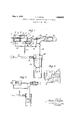
- Q a 1 'liigxl is a vertical longitudinal section through one form of the device
- Fig. 3' is a diagrammatic view partly in sec-. tion of another form of the device.
- the body o'f'the cham- I I the line leading her is made of an internally ground cylindrical pipe 10 threaded externally at the ends to receive the threaded caps 11 and 12.
- 'A piston comprising a cupJeat-her 13 held between two plates 14 and 15, moves in the cylinder 10.
- a diaphragm or any similar device may be used instead of the abovementioned piston.
- 'A stem 16 centrally connected to the piston, passes through a stuffing box 17 in the cap 12 through another stufling box 184; in the flow tubing 18- and is threaded or otherwise rigidly connected to the valve 19 which seats on the valve-seat 2-0.
- a pipe 25 of a small diameter leads from the inside of the cylinder 10 near the cap 11,
- a similar pipe 27 connects the interior of the opposite end of the cylinder 10 with a pip 28 1 leading the high pressure air or gas from the source of supply G into thev interior of the well casing 29.
- A- casing-hea-d is screwed on the top of the casing 29, and a check-valve 31 is set in the line 28 on the down-stream side of the connection of the pipe 27.
- gas pressure in line 28 acts through pipe 27 to move piston 13 against spring 24 for unseating valve 19 and permitting fluid to flow past valve seat 20.
- a bracket 32 isbolted to the cap 12 and has a lever 33 hinged to it at 34.
- a second bracket 35 projects downwardly from said cap 12 and-a spring 36 is connected to the .end of said bracket 35 and the lower end of the lever 33.
- a stop 37 on the bracket 32 keeps the lever 33 in substantially the indicated position.
- a tripping mechanism is adjustably installed on the stem 16. This mechanism consists of a body 38 adj ustably held by a setscrew and provided with a stop shoulder 39 and a swinging finger or flap 40.
- the oil-well is flowed in the ordinary manner by the introduction of air or gas under pressure into the casing 29 through the line 28, said air or gas ejecting the oil out through the tubing 18 in the direction ind cated by the arrows in Figs. 1 and 3.
- the air or as under pressure enters through the pipe 27 into the part ofthe cylinder 10 between the piston 13 and the cap 12.
- the operating pressure must befgreater than the tension of the spring 24 plus the pressure in thefiow tubing 18, so as to compress said spring 24 and hold valve 19 open thus permitting the ejection of the liquid from the well past the valve.
- check valve 31 closes, thus preventing the dissipation of the gas from the casing back into the pipe 28.
- the tripping mechanism 38 moves to the right and the flap 40 thereof, being hinged as shown in Fig. 1,
- Fig. 2 shows a typical chart of the pressure conditions in the casing.
- the valve 19 is closed by the action of the spring 24. hen the pressure starts rising and is substantially equal or slightly greater than the normal operating pressure, the valve 19.tends to open.
- the fiap 40 catches on the lever 33 and an extra pressure substantially equal to the tension of the spring 36 and represented by thequantity distance B must be created in the line 28 (and therefore in the casing 29 and in the cylinder 10) before the-aforementioned valve 19 will open.
- the lowerlimit of pressure at which the valve 19 will close is regulated by compressing the spring 24 with the screw 21, the latter being held in adjusted position by the lock-nut 22.
- the piston 13 is preferably set.
- the automatic pressure retaining device instead of being used where the well is flowedfrom the tubing, may also 'be used in conjunct on with gaslift installations in which air or gas under pressure is introduced through the tubing and the fluid is ejected through the annular space between said tubing and thegcasing.
- a wellcasing a well tubing depending in said casing, means to maintain an operating pressure in said casing, and an automatic pressure retainer comprising a liquid flow control valve mounted means responsive to a predetermined upper operating pressure, in said casing. to maintain said valve in open position and means responsive to a predetermined lower operating pressure in said casv ing to close said valve.
- a well casing a well tubmg depending in said casing,means to maintain an operating pressure in said casing, and an automatic pressure retainer comprising a valve mounted in said well tubing, means responsive to a predetermined upper operating pressure insaid" casing to maintain saidvalve in open position, means responsive to a predetermined lower operating. pressure in said casing to close said valve and means responsive to a predetermined pressure highsure retainer comprising a liquid discharge" control valve in the tubing, an actuated member-connected with the valve,
- An automatic well-pressure retainer comprising a chamber, a piston movable in the chamber, a liquid fiow control valve adapted to be mounted in a tubing and connected with the piston for actuation thereby, reg'ulable means on one side of said piston adapted. to actuate the piston toclose the tubing valve, and means to supply pressure tothe Well and-to the other side of said piston to oppose the action of first mentioned meanst Q 17.
- An automatic well-pressure retainer comprising a chamber, a liquid flow control valve adapted to be mounted in a flow tube to cut ofl flow therethrough, a piston slidably mounted in the chamber and connected to the tubing walve,-a regulable spring on one means opera tively associated with said member to move side of said piston, and a pipe leading gas i under pressure from a source of supplyto the other side-of said piston.
- a source of gas pressure a chamber connected to said source, a piston in the chamber, a casing connected to the source of gas pressure, a tubing in the casing, a liquid flow control valve on the tubing and connected to the piston, a connection for applying said pressure to the piston for holding said valve open, means to automatically close the valve when the pressure drops, and a check-valve on the casing to prevent a return of gas to the pressure supply.
- a piston in the chamber a casing connected to the source of gas pressure, a check-valve on tliecasing to prevent a return of gas from said casing to the source, a tubing in the casing, a valve on the tubing and connected to the piston, a connection for applying said pressure tothe piston for holding said valve open, means to automatically close the valve when the pressure drops, and a detent on the chamber to prevent the opening of the tubing valve untilasubstantially higher pressure is exerted on the piston.
- a casing In combination a casing, a tubing in i the casing, a valve in the tubing, a gas pres- 'suresupply tothe casing, a check-valve on the casing to prevent a return of gas to the source of supply, means controllable by said pressure to hold the valve open, means to automatically close the valve when the pressure drops, and an auxiliary control means on the chamber and valve to prevent the opening of the tubing valve until a substantially higher pressure is exerted on the piston.
- K 14 In combination a casing, means to sup-- ply gas pressure to the caslng, a check-valve on the casing to prevent pressure loss through the supply means, a tubing in the casing, a valve on the, tubing,"and means to automatically close the valve, when a predetermined lower pressure is in the supply means, and open it above said pressure.
- a'casing means to supply gas pressure to the casing, a check-valve on the casing to prevent pressure loss through the supply means, a tubingin the casinmga valve on the tubing, means to-automaticlly close'the valve below a predetermined pressure in the supply means, and an auxiliary control means to prevent the opening of said valve until a substantially higher pressure is exerted on the piston.
- liquid flow control valve on the tubing actu- 16.
- a casing means to supply gas pressure to the casing, a check-valve 1 on the casing to prevent pressure loss through the supply means, a tubing in the casing, a
- a method for automatically regulat r ing the pressure in an oil well eduction tubing connected with a gas induction pipe in which a gas pressure is maintained from a source of supply comprising the step of interrupting flow of fluid from the tubing by closing the liquidflow valve thereon when the pressure from the source of supply drops below a certain value, and the step of restoring flow of fiuid from thetubing, when the pressure from said source'of supply rises above a certain value.
- a method for automatically regulating the pressure in a liquid eduction tube leading. from a liquid supply, to whichrtube gas under pressure is supplied from a source, comprising controlling flow from the eduction tube in response to pressure variations in said source of gas supply.
- a method for automatically regulating the pressure in a liquid eduction tube leadingfrom a liquid supply, to which tube) gas under pressure is, supplied comprising permitting flow from the eduction tube when said pressure exceeds a certain'value, and interrupting the flow from said eduction, tube when the gas pressure drops below a certain value.
- a method for automatically regulat-' ing the pressure in aliquid eduction tube leading from a liquid supply, LO which tu'be gas under pressure is supplied comprising interrupting the flow from the eduction tube when gas pressure-inthe source of gas sup ply drops below. a certain value, and permitting flow from said eduction tube when said pressure exceeds a certain value.
- a liquid flow valve in the tubing a liquid flow valve in the tubing, a gas pressure supply pipeleading to the casing, means controllable by said pressure to hold the valve open, and means to automatically move the valve toward closed position when said pressure drops.
Landscapes
- Engineering & Computer Science (AREA)
- Mechanical Engineering (AREA)
- General Engineering & Computer Science (AREA)
- Control Of Fluid Pressure (AREA)
Description
y 3, 1932- J. J. KOGAN 1,856,872
AUTOMATIC PRESSURE RETAINER FOR GAS LIFT WELLS Filed July 16, 1929 INVENTOR. Jacob cffgiyazz. BY
A ORNEY.
Patented May 3, 1932 UNITED: STATES PAT ENT oF-ncE JACOB J. KOG-AN, or Los'ANGELE-s, CALIFORNIA, Assreivon ro UNION on. COMPANY,'0F CALIFORNIA, or s ANGELES, CALIFORNIA, A CORPORATION or CALIFORNIA.
. L AUTOMATIC PRESSURE RETAINER FOR- GAS ,LIFT WELLS Application filed ma 16,
- This invention relates to methods and devices adapted to be .used in oil Wells operating by the so-called air and gas lift methods, for automatically retaining the pressure in the event of a substantial or complete drop of said pressure at the source of supply.
In operating/by gas and air lift methods a flow tube is commonly used which depends into the well casing and from which the oil and gas mixture is expelled by the pressure of the introduced gas. In installations heretofore used for operation of oil wells by air and gas lift methods, when the compressor, for
' example, would stop or idle without. receiving any air or gas ejection of oil from the tubing would stop, and, since there is then 1 sure in said'tubing,
no presoil would accumulate in the latter to such a height that an excessive pressure would have to be introduced into the casing from the source for example the compressor) to raise this accumulated col- I umn of oil to the surface.
It is the object of this invention to provide a method which, in the event of a drop of pressure at the source of supply, will automatically retain the pressure in the well tubing so that this latter will prevent a further inflow of'oil into the tubing, thus facilitating the automatic starting of the flow of fluid from the Well 'when the pressure of the air or gas passing into the casing from the source again rises to a. certain predetermined value.
Broadly stated, the invention resides in operating with a. device which-will automatical- 1 close a'valve on the'tubing (or a prolongation thereof) when the pressure of the air or gas in the pipe-line leading from the source of supply to the casing has dropped below a certain predetermined value, and
which will "automatically open said valve as soon as the pressure rises to a predetermined 5 point in the aforesaid pipe-line.
In ,oneform, the invention comprises a source of gas pressure, means controlled by said pressure .for holding the valve in op'en position while a'predetermined pressure is maintained in a line leading from the source of supply to the well, and means for automati cally closing the. valve when a complete or Fig. 2 is a chart showing the fluctuation during the opera- 1929. Serial No. 378,802.
substantial drop in said pressure occurs, the latter means permitting'an automatic opening of the valve when the pressure in the said line rises to a certain value. a
The pressure controlled means in a practical embodiment comprises a chamber ver a container, a piston or similar device connected. to the stem of the valve provided in the flow tubing, and a connection for applying the pressure to the piston. The invention further comprises an auxiliary control, such as a detent or other means, positioned to re-- vent the openingof the valve, when once I closed, until a certain predetermined pressure higher than normal operating pressure is ob tained in the casing and in to it.
Referring to the accompanying drawings which disclose preferred embodiments of the invention by way of illustration: Q a 1 'liigxl is a vertical longitudinal section through one form of the device;
the pressure in the casing tion of the preferred.form'ofthedevice; Fig. 3'is a diagrammatic view partly in sec-. tion of another form of the device.
- As shown in Fig. 1 the body o'f'the cham- I I the line leading her is made of an internally ground cylindrical pipe 10 threaded externally at the ends to receive the threaded caps 11 and 12. 'A piston comprising a cupJeat-her 13 held between two plates 14 and 15, moves in the cylinder 10. A diaphragm or any similar device may be used instead of the abovementioned piston. ,'A stem 16, centrally connected to the piston, passes through a stuffing box 17 in the cap 12 through another stufling box 184; in the flow tubing 18- and is threaded or otherwise rigidly connected to the valve 19 which seats on the valve-seat 2-0. A screw 21, provided with a lock-nut 22, runs through cap 11 and is J rigidly connected to a plate 23, acompression sprlng 24 being located between said plate and the piston 13 A i I I 9: A pipe 25 of a small diameter leads from the inside of the cylinder 10 near the cap 11,
and opens into flow tubing 18 at a point 26.
A similar pipe 27 connects the interior of the opposite end of the cylinder 10 with a pip 28 1 leading the high pressure air or gas from the source of supply G into thev interior of the well casing 29. A- casing-hea-d is screwed on the top of the casing 29, and a check-valve 31 is set in the line 28 on the down-stream side of the connection of the pipe 27. With such means, gas pressure in line 28 acts through pipe 27 to move piston 13 against spring 24 for unseating valve 19 and permitting fluid to flow past valve seat 20. I
In order to control the valve movement further, a bracket 32 isbolted to the cap 12 and has a lever 33 hinged to it at 34.- A second bracket 35 projects downwardly from said cap 12 and-a spring 36 is connected to the .end of said bracket 35 and the lower end of the lever 33. A stop 37 on the bracket 32 keeps the lever 33 in substantially the indicated position. A tripping mechanism is adjustably installed on the stem 16. This mechanism consists of a body 38 adj ustably held by a setscrew and provided with a stop shoulder 39 and a swinging finger or flap 40. By this arrangement, when the valve 19 is moved so as to seat itself, the flap 4O rises into the position shown in dotted lines when passing over lever 33 and then falls on the other side of it. On the contrary when the valve is being unseated, said flap 40 abuts against the sh0ulder 39, and the stem 16 will not move until a pressure is. exerted-sufficient to overcome the tension of the spring 36, after which the lever 33 will be moved by saidtripping mechanism in its movement to the left until the flap '40 slides over said lever' 33.
In operating with this automatic pressure retainer, the oil-well is flowed in the ordinary manner by the introduction of air or gas under pressure into the casing 29 through the line 28, said air or gas ejecting the oil out through the tubing 18 in the direction ind cated by the arrows in Figs. 1 and 3. The air or as under pressure enters through the pipe 27 into the part ofthe cylinder 10 between the piston 13 and the cap 12. The operating pressure must befgreater than the tension of the spring 24 plus the pressure in thefiow tubing 18, so as to compress said spring 24 and hold valve 19 open thus permitting the ejection of the liquid from the well past the valve.
'If the pressure from the gas introduced from the source of supply, through the pipe:
' line 28 into the casing 29, falls below a certain limit, which is the tension of the spring 24 plus the pressure in tubing 18, and slnce the tension of the spring 24 is now greater than the pressure exerted on the'opposite side of the piston 13, said spring expands and moves .stem 16 to seat the valve 19 on the valve-seat 20, thus closing-the tubing 18 and retaining the gas pressure. In the meantime,
19 has reached closed position, said flap 40 hangs vertically on its hinge on the side of the lever 33 opposite to that shown in Fig. 1. Whenever the pressure in said line 28 again rises to a value slightly higher than the tension of the spring 24 plus the pressure in tubing 18, there will be a tendency to compress said spring 24 by movement of piston 13 and to unseat the valve 19. However, the flap 40 abutting against shoulder 39 of the body38 engages the lever 33, and a substantially higher pressure must thus be created in the pipe 28, and therefore in both the casing 29 and the chamber of the cylinder 10 between the piston 13 and the cap 12, to overcome the tension of the spring 36 before said spring 36 can be elongated to permit lever 33 to move to a position which will permit the flap 40 to slide over the end of said lever 33. As long as the pressure in said casing is substantially uniform, the automatic pressure retainer here disclosedmaintains the valve in open position. v
The pressure changes occurring during a complete cycle of operation as just described, are diagrammatically represented in Fig. 2, which shows a typical chart of the pressure conditions in the casing. When the pressure at the source of supply drops substantially or completely (as shown by the first downward drop A of the curve), the valve 19 is closed by the action of the spring 24. hen the pressure starts rising and is substantially equal or slightly greater than the normal operating pressure, the valve 19.tends to open. However, the fiap 40 catches on the lever 33 and an extra pressure substantially equal to the tension of the spring 36 and represented by thequantity distance B must be created in the line 28 (and therefore in the casing 29 and in the cylinder 10) before the-aforementioned valve 19 will open. The small lost motion of stem 16 causing the valve 19 to be slightly unseatedfrom the valve seat 20, beforethe flap 4O abuts against the lever 33, has a negligible effect on the loss of pressure in the tubing 18, since the rise in pressure in the casing 29 raises the fluid in said tubing 18 so as to more than overcome the mentioned pressure loss. This small lost motion is required to permit the sliding of flap 40 over lever 33 during the closing of valve 19.
The lowerlimit of pressure at which the valve 19 will close, is regulated by compressing the spring 24 with the screw 21, the latter being held in adjusted position by the lock-nut 22. The piston 13 is preferably set.
preventing, an equalization= of pressure on both sides of piston 13.
It is to be observed that the pressure stantially the same as disclosed above for Fig. -1, with the exception that the valve will open as soon as a. pressure substantially equal to the normal operating pressure is created in the line leading from the source of supply to the casing.
lVhile the method and the two devices described and shown represent desirable embodiments of the invention, nevertheless it is obvious that changes may be made without departing from the spirit of theinvention.
Thus, it is understood that the automatic pressure retaining device, instead of being used where the well is flowedfrom the tubing, may also 'be used in conjunct on with gaslift installations in which air or gas under pressure is introduced through the tubing and the fluid is ejected through the annular space between said tubing and thegcasing.
Therefore, it is to be understood that the above disclosure is merely illustrative of the generic invention and is not to be considered as limiting, many variationsbeing possible within the scope of the following claims.
1. A -method for automatically retaimng pressure in a tubing in the event of asubstantial or complete drop of gas pressure in the line leading-from the source of supply to a casing within whichthe tubing is disposed, comprising cutting ofi flow of fluid from the tubing when the pressure in the said line dropsbelow a certain value and simultaneously cutting off return of gas through the said line. w I
2. In combination a well casing, a check valve on the casing to act as casing pressure 1 retainer, a tubing in the casing, a hquid flow control valve on said tubing, and means to automatically close and open-the second valve in response to pressure variations in said casing.
"3. In combination, a wellcasing, a well tubing depending in said casing, means to maintain an operating pressure in said casing, and an automatic pressure retainer comprising a liquid flow control valve mounted means responsive to a predetermined upper operating pressure, in said casing. to maintain said valve in open position and means responsive to a predetermined lower operating pressure in said casv ing to close said valve.
4 In'combination, a well casing, a well tubmg depending in said casing,means to maintain an operating pressure in said casing, and an automatic pressure retainer comprising a valve mounted in said well tubing, means responsive to a predetermined upper operating pressure insaid" casing to maintain saidvalve in open position, means responsive to a predetermined lower operating. pressure in said casing to close said valve and means responsive to a predetermined pressure highsure retainer comprising a liquid discharge" control valve in the tubing, an actuated member-connected with the valve,
the valve toward closed position, and a'connection for applying an operative force upon said member to oppose closing movement of said valve under influence of its operative means. 1 p
6. An automatic well-pressure retainer comprising a chamber, a piston movable in the chamber, a liquid fiow control valve adapted to be mounted in a tubing and connected with the piston for actuation thereby, reg'ulable means on one side of said piston adapted. to actuate the piston toclose the tubing valve, and means to supply pressure tothe Well and-to the other side of said piston to oppose the action of first mentioned meanst Q 17. An automatic well-pressure retainer comprising a chamber, a liquid flow control valve adapted to be mounted in a flow tube to cut ofl flow therethrough, a piston slidably mounted in the chamber and connected to the tubing walve,-a regulable spring on one means opera tively associated with said member to move side of said piston, and a pipe leading gas i under pressure from a source of supplyto the other side-of said piston.
8. In a combination with a construction according to claim 7, means for gas from the side of the piston the said spring operates. 9. In combination with a construction according to claim 7, means acting in addition to and in the direction of the said spring and adapted to hold said valve in a closed position.
10. In combination a casing, a tubing in the casing, a liquid flow control'valve in the exhausting tubing, a gas pressure supply pipe to the casing, means controllable by said pressure to hold the liquid flowY'con'trolvalve open,
means to automatically closethe valve-when said pressure drops, and a valve'on the easupon which ing to prevent a return of gas to said gas supply pipe.
11. In combination a source of gas pressure, a chamber connected to said source, a piston in the chamber, a casing connected to the source of gas pressure, a tubing in the casing, a liquid flow control valve on the tubing and connected to the piston, a connection for applying said pressure to the piston for holding said valve open, means to automatically close the valve when the pressure drops, and a check-valve on the casing to prevent a return of gas to the pressure supply.
12. In combination a source of gas pressure, a chamber connected to said source, a
- piston in the chamber, a casing connected to the source of gas pressure, a check-valve on tliecasing to prevent a return of gas from said casing to the source, a tubing in the casing, a valve on the tubing and connected to the piston, a connection for applying said pressure tothe piston for holding said valve open, means to automatically close the valve when the pressure drops, and a detent on the chamber to prevent the opening of the tubing valve untilasubstantially higher pressure is exerted on the piston.
13. In combination a casing, a tubing in i the casing, a valve in the tubing, a gas pres- 'suresupply tothe casing, a check-valve on the casing to prevent a return of gas to the source of supply, means controllable by said pressure to hold the valve open, means to automatically close the valve when the pressure drops, and an auxiliary control means on the chamber and valve to prevent the opening of the tubing valve until a substantially higher pressure is exerted on the piston.
15. In combination a'casing, means to supply gas pressure to the casing, a check-valve on the casing to prevent pressure loss through the supply means, a tubingin the casinmga valve on the tubing, means to-automaticlly close'the valve below a predetermined pressure in the supply means, and an auxiliary control means to prevent the opening of said valve until a substantially higher pressure is exerted on the piston.
. liquid flow control valve on the tubing, actu- 16. In combination a casing, means to supply gas pressure to the casing, a check-valve 1 on the casing to prevent pressure loss through the supply means, a tubing in the casing, a
ating means connected. to the valve, a pressure by p ass from said supply means to move the I actuating means andvalve when pressure ex- 17. A method for automatically regulat r ing the pressure in an oil well eduction tubing connected with a gas induction pipe in which a gas pressure is maintained from a source of supply, comprising the step of interrupting flow of fluid from the tubing by closing the liquidflow valve thereon when the pressure from the source of supply drops below a certain value, and the step of restoring flow of fiuid from thetubing, when the pressure from said source'of supply rises above a certain value.-
18. A method for automatically regulating the pressure in a liquid eduction tube leading. from a liquid supply, to whichrtube gas under pressure is supplied from a source, comprising controlling flow from the eduction tube in response to pressure variations in said source of gas supply.
19. A method for automatically regulating the pressure in a liquid eduction tube leadingfrom a liquid supply, to which tube) gas under pressure is, supplied, comprising permitting flow from the eduction tube when said pressure exceeds a certain'value, and interrupting the flow from said eduction, tube when the gas pressure drops below a certain value.
20. A method for automatically regulat-' ing the pressure in aliquid eduction tube leading from a liquid supply, LO which tu'be gas under pressure is supplied, comprising interrupting the flow from the eduction tube when gas pressure-inthe source of gas sup ply drops below. a certain value, and permitting flow from said eduction tube when said pressure exceeds a certain value. v
21. In combination a deep well casing, a
. want tubing therein, a liquid flow valve in the tubing, a gas pressure supply pipeleading to the casing, means controllable by said pressure to hold the valve open, and means to automatically move the valve toward closed position when said pressure drops.
Signed. at Los Angeies, in the county of Los Angeles, and State of California, this'.-
5th day of July, A.
I JACOB J. KOGAIL-
Priority Applications (1)
| Application Number | Priority Date | Filing Date | Title |
|---|---|---|---|
| US378802A US1856872A (en) | 1929-07-16 | 1929-07-16 | Automatic pressure retainer for gas lift wells |
Applications Claiming Priority (1)
| Application Number | Priority Date | Filing Date | Title |
|---|---|---|---|
| US378802A US1856872A (en) | 1929-07-16 | 1929-07-16 | Automatic pressure retainer for gas lift wells |
Publications (1)
| Publication Number | Publication Date |
|---|---|
| US1856872A true US1856872A (en) | 1932-05-03 |
Family
ID=23494606
Family Applications (1)
| Application Number | Title | Priority Date | Filing Date |
|---|---|---|---|
| US378802A Expired - Lifetime US1856872A (en) | 1929-07-16 | 1929-07-16 | Automatic pressure retainer for gas lift wells |
Country Status (1)
| Country | Link |
|---|---|
| US (1) | US1856872A (en) |
Cited By (8)
| Publication number | Priority date | Publication date | Assignee | Title |
|---|---|---|---|---|
| US3198134A (en) * | 1961-12-19 | 1965-08-03 | Us Industries Inc | Pumping system for gas wells |
| US3203351A (en) * | 1962-11-08 | 1965-08-31 | Pan American Petroleum Corp | Apparatus for discharging liquids from wells |
| US5014789A (en) * | 1986-07-07 | 1991-05-14 | Neville Clarke | Method for startup of production in an oil well |
| US5400858A (en) * | 1993-09-13 | 1995-03-28 | International Technology Corporation | Groundwater recovery system |
| US5547021A (en) * | 1995-05-02 | 1996-08-20 | Raden; Dennis P. | Method and apparatus for fluid production from a wellbore |
| US5707214A (en) * | 1994-07-01 | 1998-01-13 | Fluid Flow Engineering Company | Nozzle-venturi gas lift flow control device and method for improving production rate, lift efficiency, and stability of gas lift wells |
| US5743717A (en) * | 1994-07-01 | 1998-04-28 | Fluid Flow Engineering Company | Nozzle-venturi gas lift flow control device |
| WO2002006677A1 (en) * | 2000-07-13 | 2002-01-24 | John Gagliardi | Multi-stage liquid elevator |
-
1929
- 1929-07-16 US US378802A patent/US1856872A/en not_active Expired - Lifetime
Cited By (9)
| Publication number | Priority date | Publication date | Assignee | Title |
|---|---|---|---|---|
| US3198134A (en) * | 1961-12-19 | 1965-08-03 | Us Industries Inc | Pumping system for gas wells |
| US3203351A (en) * | 1962-11-08 | 1965-08-31 | Pan American Petroleum Corp | Apparatus for discharging liquids from wells |
| US5014789A (en) * | 1986-07-07 | 1991-05-14 | Neville Clarke | Method for startup of production in an oil well |
| US5400858A (en) * | 1993-09-13 | 1995-03-28 | International Technology Corporation | Groundwater recovery system |
| US5452765A (en) * | 1993-09-13 | 1995-09-26 | International Technology Corporation | Groundwater recovery system |
| US5707214A (en) * | 1994-07-01 | 1998-01-13 | Fluid Flow Engineering Company | Nozzle-venturi gas lift flow control device and method for improving production rate, lift efficiency, and stability of gas lift wells |
| US5743717A (en) * | 1994-07-01 | 1998-04-28 | Fluid Flow Engineering Company | Nozzle-venturi gas lift flow control device |
| US5547021A (en) * | 1995-05-02 | 1996-08-20 | Raden; Dennis P. | Method and apparatus for fluid production from a wellbore |
| WO2002006677A1 (en) * | 2000-07-13 | 2002-01-24 | John Gagliardi | Multi-stage liquid elevator |
Similar Documents
| Publication | Publication Date | Title |
|---|---|---|
| US2339487A (en) | Time and volume control for gas | |
| US1932992A (en) | Plunger control device | |
| US1846483A (en) | Water hammer and relief valve | |
| US1856872A (en) | Automatic pressure retainer for gas lift wells | |
| US2053931A (en) | Pressure control valve | |
| US2227297A (en) | Automatic line shut-off | |
| US3351021A (en) | Free piston pneumatic arrestor and control system | |
| US3396793A (en) | Gas well dewatering controller | |
| US4417858A (en) | Plunger lift control | |
| US2310516A (en) | Valve | |
| US2649738A (en) | Control for plunger lifts | |
| US2918015A (en) | Free piston pumping device for gas wells and oil wells | |
| US1993292A (en) | Flow regulator for plunger lift pumps | |
| US2179226A (en) | Well flowing valve | |
| US2013111A (en) | Period control valve for plunger lift devices | |
| US2642811A (en) | Well flow apparatus and system | |
| US4518036A (en) | Device for controlling a safety valve disposed below an activation pump in a hydrocarbon production well | |
| US2292768A (en) | Differential pressure controlled flow valve | |
| US4453568A (en) | Gas control system | |
| US1780538A (en) | Accumulator timing element for pressure-fluid-supply valves | |
| US2763286A (en) | Automatic valve control mechanism | |
| US2018206A (en) | Apparatus for plunger lift control | |
| US1885565A (en) | Fluid pressure actuated control mechanism | |
| US3311127A (en) | Gas lift valve having particular piston seal | |
| US2265835A (en) | Intermitter valve |