US1856864A - Cooking device - Google Patents
Cooking device Download PDFInfo
- Publication number
- US1856864A US1856864A US232265A US23226527A US1856864A US 1856864 A US1856864 A US 1856864A US 232265 A US232265 A US 232265A US 23226527 A US23226527 A US 23226527A US 1856864 A US1856864 A US 1856864A
- Authority
- US
- United States
- Prior art keywords
- plates
- heating
- uprights
- arms
- plate
- Prior art date
- Legal status (The legal status is an assumption and is not a legal conclusion. Google has not performed a legal analysis and makes no representation as to the accuracy of the status listed.)
- Expired - Lifetime
Links
- 238000010411 cooking Methods 0.000 title description 3
- 238000010438 heat treatment Methods 0.000 description 28
- RTZKZFJDLAIYFH-UHFFFAOYSA-N Diethyl ether Chemical compound CCOCC RTZKZFJDLAIYFH-UHFFFAOYSA-N 0.000 description 2
- 239000004020 conductor Substances 0.000 description 2
- 230000007775 late Effects 0.000 description 2
- 241000426450 Camponotus mus Species 0.000 description 1
- 102000004726 Connectin Human genes 0.000 description 1
- 108010002947 Connectin Proteins 0.000 description 1
- 238000012550 audit Methods 0.000 description 1
- 210000005069 ears Anatomy 0.000 description 1
- 235000000396 iron Nutrition 0.000 description 1
- 239000002184 metal Substances 0.000 description 1
- 230000002093 peripheral effect Effects 0.000 description 1
Images
Classifications
-
- A—HUMAN NECESSITIES
- A47—FURNITURE; DOMESTIC ARTICLES OR APPLIANCES; COFFEE MILLS; SPICE MILLS; SUCTION CLEANERS IN GENERAL
- A47J—KITCHEN EQUIPMENT; COFFEE MILLS; SPICE MILLS; APPARATUS FOR MAKING BEVERAGES
- A47J37/00—Baking; Roasting; Grilling; Frying
- A47J37/06—Roasters; Grills; Sandwich grills
- A47J37/0611—Roasters; Grills; Sandwich grills the food being cooked between two heating plates, e.g. waffle-irons
Definitions
- This invention relates to a deviceespecially adapted for toasting sandwiches and other articles of food, although it may be utilized for other cooking operations, such as baking 5 Wailles and cooking other articles of food to which heat is applied from one or both sides.
- One object of the invention is to provide a device' of the class named whichshall be convenient to operate, economical to manufacture, strong and durable, attractive in appearance and eicient inthe preparation of food roducts.
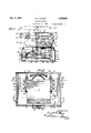
- Fig. 1 is an elevation with parts in section showlng one embodimentofthe present invention
- Fig. 2 is a top plan view of the device shown in Fig. 1;
- Fig. 3 is a vertical sectional view substantially on line 3-3 of Fig. 2;
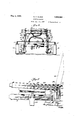
- FIg. 4 is a fragmentary elevation of the 30 heating plates supplied to Aa sandwich to be tQaste
- the invention comprises upper and lower heating plates 10 and 11 mounted on a base' 12 in a manner to move toward and away from each other while maintaining their parallel relation.
- the base 12 is ⁇ made of sheet metal and is open on the inside to accommodate electic wiring and operating mechanism.
- the ase 12 is rovided with an upstanding flange 13 to w ich a over lat ⁇ e14 is attached having downwardly nt edges secured to the flange 13 bybolts-l.
- a portion of the cover plate 14- is reinforced by a plate 16 having a peripheral liange 17. A pair of late 16 and secured thereto by bolts 21.,
- - Upright bars 26 are pivoted at 27 and 28 to the bars 22 and 24, respectively.
- the bars 26 support plate. 11, rigidly fixed to their upper ends by screws 29.
- a pair of uprights 30 pivoted at 31 and 32 respectively to the rear ends of the pivoted bars 22 and 24.
- the uprights4 30 are provided with forwardly eX- tending arms 33, the forward ends of which are disposed directly above the u per ends of the uprights 26.
- the heating p ates 10 are provided with rearwardly extending lugs 34,
- the heating plate 10 may be swunO upwardly,.as shown in broken lines in Fig. 4, until stopped 'by ears 37 on the lugs 34 which engage stop pins 38v on the uprights30.
- the forward ends of the arms 33 are provided with depressions '39 for receiving pins 40 extending laterally'fr'om the edges of the y heating plate 10. It will be seen that the pivot bars 22 Iand 24 and the uprights 26 and 30 form a parallel motion support for the heating plates 10 and 11 so that these plates may be moved toward and away from each other while retaining their parallel relation.
- Fig. 4.. the 'plates are shown in the -posi- I tion they xassume when 'the forward ends of the arms 22 and 24 are raised.
- the lower 8'5 plate is supported on the forward ends of the arms 22 and 24 and the upper plate is supported'on the rear ends of these arms so that w enoth forward endsof the arms are up, the rear ends ofthe arms will be down and "the plates 10 and 11 will be moved to ether.
- the plates '10 and 11 are provided wit hanv dles 41 and 42, respectively, and, by grasping the lower handle 42, both plates may be moved simultaneously. Bygrasping the upper-handle 41, the upper plate may be lifted away from the lower plate, as shown in'Fig. 4, while the lower plate remains stationary.
- Fixed to the rear ends of the bars 24 are brackets 43 having springs 44 connected there- 0 to adjustment with, the springs being connected by rods 45 olts 46, the forward ends of which are secured to the front face of the base 12.
- the bracket 43 will also move up and down so that the spring 44 will move past the pivotal center 2 5 of the bar 24.
- the plates 10 and 11 may be provided with any suitable form of heating element arranged within tlkeplates and current may be supplied to the heating e ement through conductors 47.
- the current to the conductors is controlled by a switch 48 whichmay be ar' ranged to supply varying amounts of current for controlling the temperature of the heating plates.
- the plane of' the upper plate will be shifted relative to the plane of the lower ⁇ plate to accommodate sandwiches or other articles of uneven thickness.
- the lugs 40 may be lifted at one or both lsides from their supporting notches 39, and the elongated .openings 36 willspermit the rear of the plate to tilt so that the plates will accommodate themselves to uneven thicknesses of articles being toasted.
- waile irons or other heating elements may be substituted, as will be readily apparent.
- a heating device including opposed parallel cooperating heating plates mounted for relative movement toward and awayfrom each other and adapted to assume an operative position with an article to be heated arranged therebetween and contacting therewith, and a spring o erative to urge said plates relatively towar each other when they are in operative position and away from each other when in open position.
- a heating' device, ⁇ including opposed parallel cooperating heating plates adapted .tive movement of said 'the lower one of said heating plates, klevers pivotally mounted n said base and a spring operative to urge said plates rela- ⁇ - tively toward each other when they are in operative position and away from eachother when in open position.
- a heating device including opposed parallel cooperating heating plates a to 'assume an operative position with an article to be heated arranged therebetween and contacting therewith, means for effecting relaplates toward and away from ,each other, and at the same time maintaining the parallelism of the plates, a spring operative to urge said plates relatively toward each other when they are in operative positionand away from each other when in open position, and means for adjusting the tension of said spring.
- a toaster comprisingl a hollow 'base member,- a pair of heating plates disposed above said base member, upri hts connected to the central portion of opp site edges of having their forward ends pivotally connected with said uprights respectively, uprights disposed adjacent the rear portion of said base and pivotally connected to the rear ends of said balance levers, the upper one of said plates being ivotally connected to said lastnamed uprig ts, arms projecting forwardly from said last-named uprights and supporting the central portion of the upper one of said lheating plates, mounted within said base and connecting the uprights of said res ective plates, a s ring disposed within said ase and connecte with ,said last-named balance levers and movable past the pivotal axis of said last-named balance levers when said plates are moved toward and away from eachother, and electrical circuits for supplying current to said heating plates.
- a toaster comprising a hollow base
- a heating plate fixed to the u per ends of said uprights substantially mi way between the front and rear of said heating plate, rights extending through the top of said base adjacent the rear thereof, a second heating plate pivotally connected at saidsecond pair of uprights,
Landscapes
- Engineering & Computer Science (AREA)
- Food Science & Technology (AREA)
- Electric Stoves And Ranges (AREA)
Description
May 3, 1932. E. c. CLAUS COOKING DEVICE FilecluNQv.` 1b, 1927 v May 3, 1932. E. c. CLAUS COOKING DEVICE Filed Nov. 10, 1927 2 Smets-sheen 2 Patented May 3, 1932 UNITED STATES-PATENT ori-ica f d.
me: c. mus, or emexico, ILLINOIS, AssIGNoB., BY Vmisma;-hssrermuiallr'ra. iro
ERNEST REICH., F CHIGAGQ, ILLINOISI y cooxme nnvrca appnadn ma november 1o, 1927. semi nel asaaes.
This invention relates to a deviceespecially adapted for toasting sandwiches and other articles of food, although it may be utilized for other cooking operations, such as baking 5 Wailles and cooking other articles of food to which heat is applied from one or both sides. One object of the invention is to provide a device' of the class named whichshall be convenient to operate, economical to manufacture, strong and durable, attractive in appearance and eicient inthe preparation of food roducts.
O er objects and advantages will appear from the followingdesciption.
Thev invention is exemplified in the combination and arrangement of parts shown in p the accompanying drawings and described in the following specification, audit is more particularly pointed out in the appended claims. v
In the drawings i Fig. 1 is an elevation with parts in section showlng one embodimentofthe present invention;
Fig. 2 is a top plan view of the device shown in Fig. 1;
Fig. 3 is a vertical sectional view substantially on line 3-3 of Fig. 2;
FIg. 4 is a fragmentary elevation of the 30 heating plates supplied to Aa sandwich to be tQaste The invention comprises upper and lower heating plates 10 and 11 mounted on a base' 12 in a manner to move toward and away from each other while maintaining their parallel relation. The base 12 is`made of sheet metal and is open on the inside to accommodate electic wiring and operating mechanism. The ase 12 is rovided with an upstanding flange 13 to w ich a over lat`e14 is attached having downwardly nt edges secured to the flange 13 bybolts-l. A portion of the cover plate 14- is reinforced by a plate 16 having a peripheral liange 17. A pair of late 16 and secured thereto by bolts 21.,
ross-bars 22 vare pivotally mounted at 23 5 0n the arms 19 and cross-bars 24 are pivotthe heating 'as shown more 'clearly in Fig. 4, the lugs bebrackets 18 havinlupwardly extending arms ally mounted at 25 on the' arms 20.- Upright bars 26 are pivoted at 27 and 28 to the bars 22 and 24, respectively. The bars 26 support plate. 11, rigidly fixed to their upper ends by screws 29. Directly in the rear of the uprights 26 is a pair of uprights 30 pivoted at 31 and 32 respectively to the rear ends of the pivoted bars 22 and 24. The uprights4 30 are provided with forwardly eX- tending arms 33, the forward ends of which are disposed directly above the u per ends of the uprights 26. The heating p ates 10 are provided with rearwardly extending lugs 34,
ing pivotally7 mounted on bolts 35 carried at the upper ends of the uprights 30. The lugs -34 are provided with elongated openings 36 which engage the bolts 35 to permit a limited movement of thel lugs on their pivot bolts. The heating plate 10 may be swunO upwardly,.as shown in broken lines in Fig. 4, until stopped 'by ears 37 on the lugs 34 which engage stop pins 38v on the uprights30.
The forward ends of the arms 33 are provided with depressions '39 for receiving pins 40 extending laterally'fr'om the edges of the y heating plate 10. It will be seen that the pivot bars 22 Iand 24 and the uprights 26 and 30 form a parallel motion support for the heating plates 10 and 11 so that these plates may be moved toward and away from each other while retaining their parallel relation.
In Fig. 4..the 'plates are shown in the -posi- I tion they xassume when 'the forward ends of the arms 22 and 24 are raised. The lower 8'5 plate is supported on the forward ends of the arms 22 and 24 and the upper plate is supported'on the rear ends of these arms so that w enoth forward endsof the arms are up, the rear ends ofthe arms will be down and "the plates 10 and 11 will be moved to ether.
The plates '10 and 11 are provided wit hanv dles 41 and 42, respectively, and, by grasping the lower handle 42, both plates may be moved simultaneously. Bygrasping the upper-handle 41, the upper plate may be lifted away from the lower plate, as shown in'Fig. 4, while the lower plate remains stationary. Fixed to the rear ends of the bars 24 are brackets 43 having springs 44 connected there- 0 to adjustment with, the springs being connected by rods 45 olts 46, the forward ends of which are secured to the front face of the base 12. When the heating plates are moved up and down, the bracket 43 will also move up and down so that the spring 44 will move past the pivotal center 2 5 of the bar 24.
When the parts are in the position shown in Fig. 1, the springs 44 will hold'the plates 10 and 11 together and will act to draw the plates toward each other until they are separated a suiiicient distance to move the springs 44 past the pivotal axis 25. This position is shown in broken lines in Fig. 1 and the arts are held in this position by the springs 44 because the springs are then shifted past their dead-center position. When the heating plates are moved slightly toward' each other from the position shown in broken lines in Fig. l, the sprlngs 44 will again move below the pivotal axis 25 and will thereafter tend to draw the plates toward each other, so that if a Asandwich or-other article to be toasted is placed between the plates, the
It will be seen that the plane of' the upper plate will be shifted relative to the plane of the lower` plate to accommodate sandwiches or other articles of uneven thickness. The lugs 40 may be lifted at one or both lsides from their supporting notches 39, and the elongated .openings 36 willspermit the rear of the plate to tilt so that the plates will accommodate themselves to uneven thicknesses of articles being toasted. Instead of toasting plates, waile irons or other heating elements may be substituted, as will be readily apparent.
Since the plates are balanced against each other by the parallel motion mechanism on les which they are mounted, they will move easily and will be held either in open or closed position by the springs 44.
I claim 1. A heating device, including opposed parallel cooperating heating plates mounted for relative movement toward and awayfrom each other and adapted to assume an operative position with an article to be heated arranged therebetween and contacting therewith, and a spring o erative to urge said plates relatively towar each other when they are in operative position and away from each other when in open position.
2. A heating' device,` including opposed parallel cooperating heating plates adapted .tive movement of said 'the lower one of said heating plates, klevers pivotally mounted n said base and a spring operative to urge said plates rela-`- tively toward each other when they are in operative position and away from eachother when in open position.
3. A heating device, including opposed parallel cooperating heating plates a to 'assume an operative position with an article to be heated arranged therebetween and contacting therewith, means for effecting relaplates toward and away from ,each other, and at the same time maintaining the parallelism of the plates, a spring operative to urge said plates relatively toward each other when they are in operative positionand away from each other when in open position, and means for adjusting the tension of said spring.
4. A toaster comprisingl a hollow 'base member,- a pair of heating plates disposed above said base member, upri hts connected to the central portion of opp site edges of having their forward ends pivotally connected with said uprights respectively, uprights disposed adjacent the rear portion of said base and pivotally connected to the rear ends of said balance levers, the upper one of said plates being ivotally connected to said lastnamed uprig ts, arms projecting forwardly from said last-named uprights and supporting the central portion of the upper one of said lheating plates, mounted within said base and connecting the uprights of said res ective plates, a s ring disposed within said ase and connecte with ,said last-named balance levers and movable past the pivotal axis of said last-named balance levers when said plates are moved toward and away from eachother, and electrical circuits for supplying current to said heating plates.
5. A toaster comprising a hollow base,
spaced uprights extending through the top of said base substantially midway between the front and rear-thereof, a heating plate fixed to the u per ends of said uprights substantially mi way between the front and rear of said heating plate, rights extending through the top of said base adjacent the rear thereof, a second heating plate pivotally connected at saidsecond pair of uprights,
apted balance a second pair vof up-v balance levers pivotally l its rear ed e to spaced ba ance levers connectin the uprights of said pairs,
respectively, to orm therewith parallel motion mechanism for supporting said heating plates, said rear uprights having arms extending forwardly and loosely supporting the central portion of the uppermost heating p1 ate, handles connected to the forward edges of said heating lates, and spring means connected with sai balance levers and movable past a dead-center position when said plates are shifted toward and away from each other and arranged to hold said plates at either extremity of their movement toward and away from each other. ,o
In testimony whereof I have si name to this specification on .this-St November, A. D. 1927.
ERNST C. CLAUS- day of ed myV
Priority Applications (1)
| Application Number | Priority Date | Filing Date | Title |
|---|---|---|---|
| US232265A US1856864A (en) | 1927-11-10 | 1927-11-10 | Cooking device |
Applications Claiming Priority (1)
| Application Number | Priority Date | Filing Date | Title |
|---|---|---|---|
| US232265A US1856864A (en) | 1927-11-10 | 1927-11-10 | Cooking device |
Publications (1)
| Publication Number | Publication Date |
|---|---|
| US1856864A true US1856864A (en) | 1932-05-03 |
Family
ID=22872459
Family Applications (1)
| Application Number | Title | Priority Date | Filing Date |
|---|---|---|---|
| US232265A Expired - Lifetime US1856864A (en) | 1927-11-10 | 1927-11-10 | Cooking device |
Country Status (1)
| Country | Link |
|---|---|
| US (1) | US1856864A (en) |
Cited By (3)
| Publication number | Priority date | Publication date | Assignee | Title |
|---|---|---|---|---|
| US2482146A (en) * | 1945-05-22 | 1949-09-20 | Baker Ally | Batter dispensing cart for baking apparatus |
| US2644880A (en) * | 1949-05-15 | 1953-07-07 | Techag A G | Electric grill |
| US2681404A (en) * | 1950-07-06 | 1954-06-15 | Hans Hofer Jr | Portable electric baking apparatus |
-
1927
- 1927-11-10 US US232265A patent/US1856864A/en not_active Expired - Lifetime
Cited By (3)
| Publication number | Priority date | Publication date | Assignee | Title |
|---|---|---|---|---|
| US2482146A (en) * | 1945-05-22 | 1949-09-20 | Baker Ally | Batter dispensing cart for baking apparatus |
| US2644880A (en) * | 1949-05-15 | 1953-07-07 | Techag A G | Electric grill |
| US2681404A (en) * | 1950-07-06 | 1954-06-15 | Hans Hofer Jr | Portable electric baking apparatus |
Similar Documents
| Publication | Publication Date | Title |
|---|---|---|
| US2033060A (en) | Grill | |
| US2465577A (en) | Toaster | |
| US2057501A (en) | Sandwich grill | |
| US1856864A (en) | Cooking device | |
| US20160166110A1 (en) | Toaster With Horizontal Translating Grill Wires | |
| US2274325A (en) | Sandwich cooker | |
| US1866874A (en) | Electric toaster | |
| US992417A (en) | Electric toaster and griddle. | |
| US1839112A (en) | Electrical cooking machine | |
| US2325551A (en) | Timed cooker | |
| US2039218A (en) | Electrical cooking machine | |
| US2266045A (en) | Automatic toaster | |
| US2520997A (en) | Baking unit | |
| US2355153A (en) | Electric toaster | |
| US2149251A (en) | Electric flatiron with self-acting safety device | |
| US2469595A (en) | Cooking apparatus | |
| US2508464A (en) | Thermal timing device | |
| US2877702A (en) | Automatic bread toaster | |
| US2180103A (en) | Pressing and ironing machine | |
| US1722127A (en) | Sandwich toaster | |
| US1778263A (en) | Electrical cooking device | |
| US2790887A (en) | Domestic appliance | |
| US2818011A (en) | Automatic cooking appliance | |
| US1659610A (en) | Bread and sandwich toaster | |
| US1181722A (en) | Broiler. |