US1856863A - Pipe annealing furnace - Google Patents
Pipe annealing furnace Download PDFInfo
- Publication number
- US1856863A US1856863A US326130A US32613028A US1856863A US 1856863 A US1856863 A US 1856863A US 326130 A US326130 A US 326130A US 32613028 A US32613028 A US 32613028A US 1856863 A US1856863 A US 1856863A
- Authority
- US
- United States
- Prior art keywords
- runways
- furnace
- pipes
- pipe
- fingers
- Prior art date
- Legal status (The legal status is an assumption and is not a legal conclusion. Google has not performed a legal analysis and makes no representation as to the accuracy of the status listed.)
- Expired - Lifetime
Links
- 238000000137 annealing Methods 0.000 title description 8
- 238000010276 construction Methods 0.000 description 3
- XEEYBQQBJWHFJM-UHFFFAOYSA-N Iron Chemical compound [Fe] XEEYBQQBJWHFJM-UHFFFAOYSA-N 0.000 description 2
- 229910001018 Cast iron Inorganic materials 0.000 description 1
- 229910052742 iron Inorganic materials 0.000 description 1
- 238000000034 method Methods 0.000 description 1
- 238000007665 sagging Methods 0.000 description 1
Images

Classifications
-
- C—CHEMISTRY; METALLURGY
- C21—METALLURGY OF IRON
- C21D—MODIFYING THE PHYSICAL STRUCTURE OF FERROUS METALS; GENERAL DEVICES FOR HEAT TREATMENT OF FERROUS OR NON-FERROUS METALS OR ALLOYS; MAKING METAL MALLEABLE, e.g. BY DECARBURISATION OR TEMPERING
- C21D9/00—Heat treatment, e.g. annealing, hardening, quenching or tempering, adapted for particular articles; Furnaces therefor
- C21D9/08—Heat treatment, e.g. annealing, hardening, quenching or tempering, adapted for particular articles; Furnaces therefor for tubular bodies or pipes
Definitions
- My invention relates to pipe annealing furnaces and particularly to the mechanism for supporting the pipes in and moving them through the furnace.
- the object of my 1nvention is particularly to provide means for supporting and transporting the pipes through the furnace which would be of such a character that the pi es will have no tendency to roll forwar on the runways which support them; to provide runways of such a character that the portions of the pipe in contact with the runways will continu-l ously change as the pipes move forward through the furnace; to provide means for adjusting the lplane of the runways and to provide propel ing fingers adapted to engage the pipes in such a way that in case of obstructions occurring-on-tl1e runways the hn' fers will tend to lift the pipes over them.
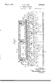
- Figure-1 is a longitudinal vertical section through a furnace provided with my improvements.
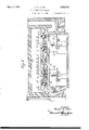
- Figure 2 is'a 'cross section on the line 2 2 3;-3 of Fig-1, and :.:f
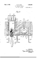
- Figure 4 is a fragmentary viewshowing de ⁇ tails of construction.
- A indicates the furnace which 'is of usual A type and which it will be understood is here ⁇ rather diagrammatically shown, that is to lsay, no attention has been paidto the prof ⁇ portions of the furnace.
- B, B, etc.. are a' series of columns supporting beams indicated at'B1 which in turn support the beams indii cated at B2. On this'last series ofloeams is supported the bottom of the furnace 'indicated at -D and D1.
- C, C, etc. are a' series pchair support C2.
- runways are set at an angle to the line of travel of the pipes through the furnace and so disposed as to form a series of runways extending through the length of the furnace, which runways are preferably set in the plane sloping upward from the entrance to the exit of the furnace and in no case is the plane of the runways inclined downward toward the exit of the furnace, that is to say, the plane of the runways may be horizontal but,Y for the best results, should beslanted upward as described.
- the chairs supporting' the rails or beams formlng the runways are vertically adjustable, as shown, by means of screws F, the threads of which are engaged with the in sie ternally threaded nut C and upon which rest. 5
- yAlso supported on the beams B2 are run ways indicated at G, havin 1 wearing plates G1' at their bottom A4'cnvvhic I3. These runways are open at the top, as
- I indicates a'motor operatively connected to a shaft I1, to. which shaft are secured p sprocketl wheels indicated at' I2, I2. These l “Sprocketwheels engage and propel the chains indicated at Is which, at the opposite end of the furnace, pass over sprocket wheels .2 secured on the shaft Secured to the links of the chain are the pipe propelling fingers indicated at il.
- K, K indicate supporting wheels, the upper surfaces of which contact with the chains and prevent too great sagging of the chains.
- L, L, etc. indicate pipes passing through the furnace.
- a pipe annealing furnace having at its bottom runways for supporting the pipe disposed in a plane lying within a range of angular positions between the horizontal and various upwardly inclined angles from the entrance to the exit of the furnace in combination with spaced ushing fingers adapted to project upward eyond the runways to engage the pipes supported thereon and adapted in connection with the lane of the runways to maintain contact wit the rear of e
Landscapes
- Chemical & Material Sciences (AREA)
- Engineering & Computer Science (AREA)
- Physics & Mathematics (AREA)
- Thermal Sciences (AREA)
- Crystallography & Structural Chemistry (AREA)
- Mechanical Engineering (AREA)
- Materials Engineering (AREA)
- Metallurgy (AREA)
- Organic Chemistry (AREA)
- Supports For Pipes And Cables (AREA)
Description
May 3, i932.
s. is. CLARKv PIPE ANNEALING FURNACE v 4 Sheets-Sheet l f Filed Deo.. 14. 1928 y n IC nu. n; u
WN NWJ@ Nm. Nm
www
. INVENTOR l .Suarf' Clark 3x/MQW ATTORNEY s. B. CLARK 1,856,863
PIPE ANNEALING FURNACE Filed Dec. 14. 1928 4 Sheets-Sheet 2 l vINVENT R Sunr C/)ark ATTORNEY c J y.
u mmmnw u w@ May 3, 1932.
` BWM' K R A L C B s May 3, 1932.
Filed Dec. 14. 1928 4 Sheets-Sheet 3 'JLM-.n Hlvllllll A ||l|||||| ..-|}|||l--|-2:21511..----1:22. lill- I||||, n ..7 I l l l I l I I l I l l l l I i-lul. l l l l l r l l l I l l l l l l I l l I I l t l l l l I I l I I I I l I ll I j MQ ATTORNEY d May 3, 1932- s. B. CLARK 1,856,863
l PIPE ANNEALING FURNACE Filed Dec. 14. 1928 4 Sheets-Sheet 4 INVENTOR uarf' Clark ATTORNEY Patented May 3, 1932 UNITED STATES Jeni STUART B. CLARK, 0F RIVEBTON, NEW JERSEY, ASSIGNOR 'IO UNITED STATES GT IRON PIPE t FOUNDRY COMPANY, OF BURLINGTON, NEW JERSEY, A CORPORATIQE' 0F NEW JERSEY PIPE ANNEALING FURNACE Application filed December 14, 192B.v Serial No. 326,130.
My invention relates to pipe annealing furnaces and particularly to the mechanism for supporting the pipes in and moving them through the furnace. The object of my 1nvention is particularly to provide means for supporting and transporting the pipes through the furnace which would be of such a character that the pi es will have no tendency to roll forwar on the runways which support them; to provide runways of such a character that the portions of the pipe in contact with the runways will continu-l ously change as the pipes move forward through the furnace; to provide means for adjusting the lplane of the runways and to provide propel ing fingers adapted to engage the pipes in such a way that in case of obstructions occurring-on-tl1e runways the hn' fers will tend to lift the pipes over them.
y preference I arrange the runways in a plane which slopes upward from the ventrance to the exit of the furnace and in all cases I so dispose the runways that they will have no downward slant toward the rear end of the furnace.`
My invention will be best understood as described in connection with the drawings and the novel features which I desire to protect by Letters Patent will beclearly pointed out.`
in the claims. p
In the drawings Figure-1 is a longitudinal vertical section through a furnace provided with my improvements.
Figure 2 is'a 'cross section on the line 2 2 3;-3 of Fig-1, and :.:f
Figure 4 is a fragmentary viewshowing de`` tails of construction. Y
A indicates the furnace which 'is of usual A type and which it will be understood is here `rather diagrammatically shown, that is to lsay, no attention has been paidto the prof` portions of the furnace. B, B, etc.. are a' series of columns supporting beams indicated at'B1 which in turn support the beams indii cated at B2. On this'last series ofloeams is supported the bottom of the furnace 'indicated at -D and D1. C, C, etc., are a' series pchair support C2. C3
l shown,
of internally threaded nuts supported on the Figure 3, are set at an angle to the line of travel of the pipes through the furnace and so disposed as to form a series of runways extending through the length of the furnace, which runways are preferably set in the plane sloping upward from the entrance to the exit of the furnace and in no case is the plane of the runways inclined downward toward the exit of the furnace, that is to say, the plane of the runways may be horizontal but,Y for the best results, should beslanted upward as described.
The chairs supporting' the rails or beams formlng the runways are vertically adjustable, as shown, by means of screws F, the threads of which are engaged with the in sie ternally threaded nut C and upon which rest. 5
the cross bars C3 of the vertically movabe .As shown, the cross bars are perforated to receive and engage threaded ends of rods F1 the adjusting screw F and having nut screwed on theirlower ends.
yAlso supported on the beams B2 are run ways indicated at G, havin 1 wearing plates G1' at their bottom A4'cnvvhic I3. These runways are open at the top, as
in the bottom ofthe furnace to give passage to the fingers which'are attached to the chains'.
I indicates a'motor operatively connected to a shaft I1, to. which shaft are secured p sprocketl wheels indicated at' I2, I2. These l "Sprocketwheels engage and propel the chains indicated at Is which, at the opposite end of the furnace, pass over sprocket wheels .2 secured on the shaft Secured to the links of the chain are the pipe propelling fingers indicated at il. These fingers are of such length that their upper sel extending through a clamping i rest the chains and communicate with slots d1 formed ice ends extend beyond the plane of the runways so as to engage the pipes supported on the runways and the novel feature of my construction consists in forming the pipe engaging ends of the fingers with a considerab e rearward slant withl reference to the plane of the runway so that they will engage the pipes on their under sides. As shown, the
ngers have their upper ends J1. formed with slants in both directions, thus providing for a reversal of the fingers in case their pipe contacting surfaces become worn. To function properly the angle of the contacting portion of the fingers to the plane of the runway should not be less than 30 to the plane of the runway. c C
K, K, indicate supporting wheels, the upper surfaces of which contact with the chains and prevent too great sagging of the chains.
L, L, etc., indicate pipes passing through the furnace.
In operation the pipes to be annealedfor instance, cent'rifugally cast cast iron pipes made by the de Lavaud process, are fed to the runways at the entrance of the furnace, indicated at A1, each pipey in the construction shown being en aged by two of the fingers J, the chain being in motion in the direction indicated by the arrow in Figure l. The pipes are carried forward by the contacting ends of the fingers over the horizontal or preferably upwardly inclined runways,
, keeping constant contact with their propelling fingers and having no tendency to roll forward into contact with the fingers in front of them. This is important because Very slight impacts with highly heated pipes are apt to deform them. In case of obstructions being met with on the runways, the inclined contacting ends of the fingers tendto lift the pipes over such obstructions. The pipes pass through the furnace and are delivered at the exit end thereof, indicated at A2 and in their travel over the runways, by reason 'of the angular set of the rails making up the runways, the portion of the pipes in contact with the runways is constantly shifting and this is a feature of importance as if the contact was always with the same portion of the pipe there would be some tendency v*to deformation or uneven annealing.
B providing means as described for adjusting* the rails or beams forming theI runways am enabled to maintain the plane of the runways at the best angle and to provide for slight deformation of the rails as by I warping.
Having now described my invention,` what I claim as new and desire to secure by Letters Patent, is:
1.- A pipe annealing furnace having at its bottom runways for supporting the pipe disposed in a plane lying within a range of angular positions between the horizontal and various upwardly inclined angles from the entrance to the exit of the furnace in combination with spaced ushing fingers adapted to project upward eyond the runways to engage the pipes supported thereon and adapted in connection with the lane of the runways to maintain contact wit the rear of e
Priority Applications (1)
| Application Number | Priority Date | Filing Date | Title |
|---|---|---|---|
| US326130A US1856863A (en) | 1928-12-14 | 1928-12-14 | Pipe annealing furnace |
Applications Claiming Priority (1)
| Application Number | Priority Date | Filing Date | Title |
|---|---|---|---|
| US326130A US1856863A (en) | 1928-12-14 | 1928-12-14 | Pipe annealing furnace |
Publications (1)
| Publication Number | Publication Date |
|---|---|
| US1856863A true US1856863A (en) | 1932-05-03 |
Family
ID=23270937
Family Applications (1)
| Application Number | Title | Priority Date | Filing Date |
|---|---|---|---|
| US326130A Expired - Lifetime US1856863A (en) | 1928-12-14 | 1928-12-14 | Pipe annealing furnace |
Country Status (1)
| Country | Link |
|---|---|
| US (1) | US1856863A (en) |
Cited By (1)
| Publication number | Priority date | Publication date | Assignee | Title |
|---|---|---|---|---|
| US2487354A (en) * | 1945-02-14 | 1949-11-08 | Anchor Hocking Glass Corp | Conveyer for changing course of articles from single to plural rows |
-
1928
- 1928-12-14 US US326130A patent/US1856863A/en not_active Expired - Lifetime
Cited By (1)
| Publication number | Priority date | Publication date | Assignee | Title |
|---|---|---|---|---|
| US2487354A (en) * | 1945-02-14 | 1949-11-08 | Anchor Hocking Glass Corp | Conveyer for changing course of articles from single to plural rows |
Similar Documents
| Publication | Publication Date | Title |
|---|---|---|
| US2067583A (en) | Device for feeding coal furnaces | |
| US1856863A (en) | Pipe annealing furnace | |
| US2446772A (en) | Combined wet screening and shredding apparatus | |
| US1481366A (en) | Grate bar to burn pulverized coal | |
| US1791752A (en) | Hopper-feed for coal stokers | |
| US1367049A (en) | Hardening-machine | |
| US1033219A (en) | Endless-belt ore-concentrator. | |
| US1297372A (en) | Mineral-separating apparatus. | |
| US939936A (en) | Roasting-furnace. | |
| US1603997A (en) | Process and apparatus for dry separation of the elements composing a mass | |
| US1315881A (en) | Process of and apparatus for separating and grading material | |
| US1352607A (en) | Mechanism for guiding and spacing candy | |
| US2006269A (en) | Ore reducing machine | |
| US1858678A (en) | Sheet metal normalizing furnace | |
| DE481554C (en) | Process and device for burning fine-grain coal on traveling grates | |
| US980202A (en) | Ore-concentrator and sliming-table. | |
| US1169242A (en) | Boiler-furnace-feeding device. | |
| US1563762A (en) | Stoker | |
| US3294044A (en) | Grate bar | |
| US2804850A (en) | Clinker pushing device for shaft furnaces | |
| US1445218A (en) | Sugar-cane-mill-feed controller | |
| US1397367A (en) | Continuous heating-furnace | |
| US1589217A (en) | Retort | |
| US2940743A (en) | Furnace hearth | |
| US585622A (en) | Furnace for heating ingots |