US1856860A - Still - Google Patents
Still Download PDFInfo
- Publication number
- US1856860A US1856860A US230245A US23024527A US1856860A US 1856860 A US1856860 A US 1856860A US 230245 A US230245 A US 230245A US 23024527 A US23024527 A US 23024527A US 1856860 A US1856860 A US 1856860A
- Authority
- US
- United States
- Prior art keywords
- chamber
- tubes
- vaporizing
- vaporizing chamber
- line
- Prior art date
- Legal status (The legal status is an assumption and is not a legal conclusion. Google has not performed a legal analysis and makes no representation as to the accuracy of the status listed.)
- Expired - Lifetime
Links
- 230000008016 vaporization Effects 0.000 description 40
- 239000003921 oil Substances 0.000 description 14
- 239000012530 fluid Substances 0.000 description 9
- 238000010438 heat treatment Methods 0.000 description 8
- 239000007788 liquid Substances 0.000 description 8
- 239000004215 Carbon black (E152) Substances 0.000 description 6
- 229930195733 hydrocarbon Natural products 0.000 description 6
- 150000002430 hydrocarbons Chemical class 0.000 description 6
- 238000004891 communication Methods 0.000 description 4
- 230000000694 effects Effects 0.000 description 3
- 238000002485 combustion reaction Methods 0.000 description 2
- 238000004821 distillation Methods 0.000 description 2
- 238000000034 method Methods 0.000 description 2
- 239000000779 smoke Substances 0.000 description 2
- 239000011449 brick Substances 0.000 description 1
- 238000009833 condensation Methods 0.000 description 1
- 230000005494 condensation Effects 0.000 description 1
- 238000010276 construction Methods 0.000 description 1
- 239000010779 crude oil Substances 0.000 description 1
- 238000012986 modification Methods 0.000 description 1
- 230000004048 modification Effects 0.000 description 1
- 239000003208 petroleum Substances 0.000 description 1
- 238000005201 scrubbing Methods 0.000 description 1
- 239000007921 spray Substances 0.000 description 1
- 238000005507 spraying Methods 0.000 description 1
- 238000009834 vaporization Methods 0.000 description 1
- 238000005406 washing Methods 0.000 description 1
Images

Classifications
-
- B—PERFORMING OPERATIONS; TRANSPORTING
- B01—PHYSICAL OR CHEMICAL PROCESSES OR APPARATUS IN GENERAL
- B01D—SEPARATION
- B01D3/00—Distillation or related exchange processes in which liquids are contacted with gaseous media, e.g. stripping
- B01D3/02—Distillation or related exchange processes in which liquids are contacted with gaseous media, e.g. stripping in boilers or stills
Definitions
- a still further feature of the invention is to provide an apparatus, as above described, and for the purposes stated, which embodies means for relieving the vapors, generated in the vaporizing chamber, from said chamber, and means for relieving the unvaporized stock oil from said chamber, as well as means effective to spray the incoming crude .oil through the outgoing vapors, thus effecting the scrubbing of said vapors and returning the undesired fractions, from said vapor,into
- a still further feature of the invention resides in the provision of an apparatus
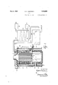
- Figure 2 shows a partial plan view thereof, partly in section.
- the numeral 1 designates the outer shell and the numeral 2 designates an inner shell within the lower part of said outer shell and spaced from the walls thereof.
- the inner shell may be lined with a suitable heat resisting lining 3, which may be composed of fire brick, or the like.
- the upper end of the inner shell supports a lower tube sheet 4 and mounted in the upper part of the outer shell there is an upper tube sheet 5 and the lower and-upper tube sheets support the lower and upper ends of the boiler tubes 6.
- a furnace 7 provided with the usual manhole 8, between the outer and inner shells, andhaving leak-proof joints therewith.
- the heated air fromthe furnace, together vwith the flames of combustion, will pass up through'the tubes 6', the smoke and products of combustion passing out through the smoke stack '9, at the top of the still.
- an independent unit comprising the router and innerspaced walls 10,11 the outer of whichis spaced from the outer shell erably arranged in tiers, one above the other,
- each tier may be arranged in staggered relation with respect to the tubes of adjacent tiers so that, the fluid dripping from one tube will fall onto a tube beneath.
- the chamber 14, and between the tubes 6 will be heated by said tubes and will rise and pass outwardly through the tubes 16 and heat them and a circulation of the heating fluid will be set up throughout the chamber 14, and the vaporizing chamber will be heat-ed thereby to the temperature required.
- the upper end plate 13 is provided with an annular fluid inlet chamber 18, which is provided with suitable-outlet openings 19, above the chamber 15, thus forming, in effect, an annular nozzle through which the oil to be treated is discharged in fine streams, or drops, onto the tubes 16, beneath.
- An inlet line 20 enters the chamber 18 and incorporated therein there is a force pump 21 and a heat exchanger casing 22. This inlet line 20 is connected with the well or other source of supply;
- the upper end plate 13 also has an annular vapor outlet chamber 23, which has suitable inlet ports 24 and connected with the vapor outlet chamber 23 there is a vapor outlet line 25 which is formedinto a coil 26 in the casing 22 and incorporated into said line 25 there is a pump 27 which maintains a partial vacuum in the chamber 15.
- outlet oil line 28 Leading from the lower part of the vaporizing chamber 15 there is an outlet oil line 28, which is formed with a heat exchanger casing 29 through which the inlet line 20 passes and in which said inlet line is formed into a coil 30.
- the chamber 14 may be filled, through the inlet 31, with a liquid which will not be vaporized by the required temperature of approximately 300 F., to which the oil to be treated is to be subjected.
- the level of the liquid in the chamber 14 may be determined by the use of a conventional gauge, as 32.
- the oil to be treated passes in through the line 20, passing through the heat exchangers 22, 29 where it is partially heated, and enters the chamber, 18, and thence trickles down, in fine streams, or drops, successively over the baffle-tubes 16 by which the desired fractions are vaporized.
- the vapors pass upwardly, through the incoming streams of oil, enter the chamber 23, and pass out through the line 25 in the coil 26 of which it is condensed.
- the unvaporized portion of the stock oil is taken ofi through the line 28 through the exchanger 29, in which it assists in heating the incoming oil passing through the coil 30 and is thence delivered to the storage tanks.
- a relief line 33 connected into the top of said chamber 14 and also connected into the line 20 and controlled by the back pressure valve 34.
- a device of the character described comprising an annular vaporizing chamber, means for circulating a heating medium around said chamber circumferentially,-baffie tubes disposed across said chamber said around said chamber circumferentially, baffie tubes through said chamber open at both ends to permit the circulation of said medium therethrough in either direction, means for delivering a liquid hydrocarbon into said chamber above said tubes to effect the flow of the hydrocarbon downwardly over the tubes and the fractional vaporizing thereof, means for taking ofi" the vapors from the top of the chamber and means for removing the unvaporized hydrocarbon from the bottom of said chamber.
- An apparatus of the character described including an annular vaporizing chamber, having tubular battles herethrough, a circulation chamber surrounding the vaporizing chamber, a liquid heating medium in the circulating chamber provided to be circulated about the vaporizing chamber and through said bafiies, a nozzle around the upper part of the vaporizing chamber through which a hydrocarbon may be fed downwardly over said battles, an inlet line terminating in said nozzle, a vapor outlet chamber in communication with said vaporizing chamber. an outlet line connected with said vapor outlet chamber, a discharge line leading out from the lower part of said vaporizing chamber.
- An apparatus of the character described including an annular vaporizing chamber, having tubular bafiles therethrough, a circulation chamber surrounding the vaporizing chamber, a liquid heating medium in the circulating chamber provided to be circulated about the vaporizing chamber and through said baiiies, a nozzle around the upper part of the vaporizing chamber through which a hydrocarbon may be fed downwardly over said bafltles, an inlet line terminating in said nozzle, a vapor outlet chamber above and in communication with said vaporizing chamber, an outlet line connected with said vapor outlet chamber, a discharge line leading out from the lower partof said vaporizing chamber, a heat exchanger incorporated into said inlet line and through which said vapor outlet line passes.
- An apparatus of the character described including an annular vaporizing chamber, having tubular bafi'ies therethrough, a circulation chamber surrounding the vaporizing chamber, a liquidheating medium in the circulating chamber provided to be circulated about the vaporizing chamber and back and forth through said baflies, a nozzle around the upper part of the vaporizing chamber and through which a fluid may be fed downwardly over said battles, an inlet line terminating in said nozzle, a vapor outlet chamber above and in communication with said vaporizing chamber, an outlet line connected with said vapor outlet chamber, a discharge line leading out from the lower part of said vaporizing chamber, a heat exchanger incorporated into said discharge line and through which said inlet line passes.
- An apparatus of the character described including an annular vaporizing chamber, having tubular baffles therethrough, a circulation chamber surrounding the vaporizing chamber, a liquid heating'medium in the circulating chamber provided to be circulated about the vaporizing chamber and back and forth through said bafliles, a nozzle around the upper part of vthe vaporizing chamber through which a hydrocarbon may be fed downwardly over saidba-flies, an inlet lineterminating in said nozzle, a vapor outlet chamber above and in communication with'said vaporizing chamber, an outlet line connected with said vapor outlet chamber, a discharge line leading out from the lower part of said vaporizing chamber, a heat exchanger incorporated into said inlet line and through which said vapor outlet passes, and a heat exchanger incorporated into the discharge line through which said inlet line passes.
- An apparatus of the character described including an outer shell and an inner shell within the lower part thereof and spaced from the walls of the outer shell, a lower tube sheet supported on the inner shell and an upper tube sheet spaced above said lower tube sheet,
- tubes whose upper and lower ends are anchored to the upper and lower sheets respectively said inner shell inclosing a furnace from which the tubes lead, and independent unit in the upper part of the outer shell and comprising outer and inner spaced walls said outer wall being spaced from the outer shell and the inner wall surrounding said tubes and upper tube sheet, lower and upper plates closing the space between said outer and inner walls and thus inclosing a vaporizing chamber between said walls, baffle tubes whose ends are anchored to said respective walls and which are open throughout, an annular fluid inlet chamber having outlet openings into the upper party of the vaporizing chamber, an inlet line entering said inlet chamber, an annular'vapor outlet chamber having outlet ports leading from said vaporizing chamber, a vapor outlet line leading from said vapor outlet chamber and a drain outlet line leading from the lower part of vaporizing chamber.
- An apparatus of the character described including an outer shell, an inner shell within the lower part thereof and'spaced from the e walls of the outer shell, tube supports, one above the other, tubes whose upper and lower ends are anchored to said upper and lower supports respectively, said inner shell inclosing a furnace above which the tubes are located and from which said tubes lead, an independent unit around the tubes and comprising outer and inner walls spaced apart, the outer wall being spaced from the outer shell, means closing the space between said outer and inner walls, said means being spaced apart and thus inclosing a vaporizing chamber between said walls, baflle tubes whose ends are anchored to said respective walls and which are open throughout, a fluid inlet chamber having outlets'opening into the upper part of the vaporizing chamber and through which fluid may be discharged onto said baffle tubes around said vaporizing chamber, an inlet line entering said inlet chamber, a vapor outlet chamber having outlet ports leading from said vaporizing chamber, and a vapor outlet line leading from said vapor outlet chamber.
Landscapes
- Chemical & Material Sciences (AREA)
- Chemical Kinetics & Catalysis (AREA)
- Vaporization, Distillation, Condensation, Sublimation, And Cold Traps (AREA)
Description
May 3, 1932.
Filed Nov. 1, 1927 2 Sheets-Sheet I l ll I N V ENTO R ATTORNEY? M y 1932- o. ANDERSON 1,856,860
STILL Filed Nov. 1, 1927 2 Sheets-Sheet 2 ATTORNEY.S.
Patented May 3, 1932 UNITED STATES PATENT OFFICE nnxroan o. ANDERSON, 0F nousron, TEXAS STILL Application filed November 1, 1927. Serial No. 230,245.
out loss of parts, and moved from place to provide an apparatus of the character de-' scribed embodying a vaporizing chamber, equipped with circulating tubes through which a heating fluid maybe circulated, and a header, into which the supply line is connected, and which is perforated, forming, in effect, a nozzle by means of which the crude petroleum, is delivered, in drops, 'or small streams, onto the heated tubes, and permitted to trickle down over them from the upper to the lower thereby exposing ajgreater proportion of the oil being treated, to the heating surfaces, than would be the case were the crude oil delivered into the vaporizing chamher in a mass, to the end that rate of heat transfer will be greatly increased.
A still further feature of the invention is to provide an apparatus, as above described, and for the purposes stated, which embodies means for relieving the vapors, generated in the vaporizing chamber, from said chamber, and means for relieving the unvaporized stock oil from said chamber, as well as means effective to spray the incoming crude .oil through the outgoing vapors, thus effecting the scrubbing of said vapors and returning the undesired fractions, from said vapor,into
the still and thence out with the unvaporized stock.
A still further feature of the invention resides in the provision of an apparatus,
whereby a novel process of distillation, hereinafter'desoribed and claimed, may be carried out. i
With the above and other objects in view this invention has particular relation to certain novel features of construction, operation and arrangement of parts an example of which is given in this specification and illustrated in the accompanying drawings, wherein Figure 1 shows a side elevation of the completeapparatus partly in section, and
Figure 2 shows a partial plan view thereof, partly in section.
Referring now more particularly to the drawings, wherein like numerals of reference designate similar parts in each of the figures the numeral 1 designates the outer shell and the numeral 2 designates an inner shell within the lower part of said outer shell and spaced from the walls thereof. The inner shell may be lined with a suitable heat resisting lining 3, which may be composed of fire brick, or the like. The upper end of the inner shell supports a lower tube sheet 4 and mounted in the upper part of the outer shell there is an upper tube sheet 5 and the lower and-upper tube sheets support the lower and upper ends of the boiler tubes 6.
Within the inner shell there is a furnace 7 provided with the usual manhole 8, between the outer and inner shells, andhaving leak-proof joints therewith. The heated air fromthe furnace, together vwith the flames of combustion, will pass up through'the tubes 6', the smoke and products of combustion passing out through the smoke stack '9, at the top of the still. I
Fitted into the upper part of the outer shell there is an independent unit comprising the router and innerspaced walls 10,11 the outer of whichis spaced from the outer shell erably arranged in tiers, one above the other,
and the tubes of each tier may be arranged in staggered relation with respect to the tubes of adjacent tiers so that, the fluid dripping from one tube will fall onto a tube beneath.
The heat conducting fluid, or medium, in
the chamber 14, and between the tubes 6 will be heated by said tubes and will rise and pass outwardly through the tubes 16 and heat them and a circulation of the heating fluid will be set up throughout the chamber 14, and the vaporizing chamber will be heat-ed thereby to the temperature required.
The upper end plate 13 is provided with an annular fluid inlet chamber 18, which is provided with suitable-outlet openings 19, above the chamber 15, thus forming, in effect, an annular nozzle through which the oil to be treated is discharged in fine streams, or drops, onto the tubes 16, beneath. An inlet line 20 enters the chamber 18 and incorporated therein there is a force pump 21 and a heat exchanger casing 22. This inlet line 20 is connected with the well or other source of supply;
The upper end plate 13 also has an annular vapor outlet chamber 23, which has suitable inlet ports 24 and connected with the vapor outlet chamber 23 there is a vapor outlet line 25 which is formedinto a coil 26 in the casing 22 and incorporated into said line 25 there is a pump 27 which maintains a partial vacuum in the chamber 15.
Leading from the lower part of the vaporizing chamber 15 there is an outlet oil line 28, which is formed with a heat exchanger casing 29 through which the inlet line 20 passes and in which said inlet line is formed into a coil 30.
The chamber 14 may be filled, through the inlet 31, with a liquid which will not be vaporized by the required temperature of approximately 300 F., to which the oil to be treated is to be subjected. The level of the liquid in the chamber 14 may be determined by the use of a conventional gauge, as 32.
The oil to be treated passes in through the line 20, passing through the heat exchangers 22, 29 where it is partially heated, and enters the chamber, 18, and thence trickles down, in fine streams, or drops, successively over the baffle-tubes 16 by which the desired fractions are vaporized. The vapors pass upwardly, through the incoming streams of oil, enter the chamber 23, and pass out through the line 25 in the coil 26 of which it is condensed. The unvaporized portion of the stock oil is taken ofi through the line 28 through the exchanger 29, in which it assists in heating the incoming oil passing through the coil 30 and is thence delivered to the storage tanks.
By passing the oil to be treated through the heat exchangers 22, 29, to increase its temperature and then spraying it into the chamber 15 and through the vapors passing out from said chamber the incoming oil will wash'said vapors and bring them to the right temperature, and by doing so will condense the vapors of any grade of oil, not desired, that may have been vaporized by having been brought to a temperature in excess of that necessary to vaporize the grade of oil desired. This operation of washing the vapors of a liquid, while in the operation of distillation, with the same, or other, liquid held at the temperature at which the vapors are desired cuts out and condenses the vapors not wanted, and in so doing comprises a fractionating condensation process.v
In order to relieve the chamber 14 from excess pressure, that may be caused by the vaporization of thefluid therein,there is a relief line 33 connected into the top of said chamber 14 and also connected into the line 20 and controlled by the back pressure valve 34.
While I have shown what I now consider the preferred form of the invention it is obvious that mechanical changes may be made therein and equivalents substituted for-the parts shown and I hereby reserve the right to make such mechanical changes and modifications as may be found desirable so long as I do not depart from the principle of the invention as comprehended within the scope of the appended claims.
What I claim is 1. A device of the character described comprising an annular vaporizing chamber, means for circulating a heating medium around said chamber circumferentially,-baffie tubes disposed across said chamber said around said chamber circumferentially, baffie tubes through said chamber open at both ends to permit the circulation of said medium therethrough in either direction, means for delivering a liquid hydrocarbon into said chamber above said tubes to effect the flow of the hydrocarbon downwardly over the tubes and the fractional vaporizing thereof, means for taking ofi" the vapors from the top of the chamber and means for removing the unvaporized hydrocarbon from the bottom of said chamber.
3. An apparatus of the character described including an annular vaporizing chamber, having tubular battles herethrough, a circulation chamber surrounding the vaporizing chamber, a liquid heating medium in the circulating chamber provided to be circulated about the vaporizing chamber and through said bafiies, a nozzle around the upper part of the vaporizing chamber through which a hydrocarbon may be fed downwardly over said battles, an inlet line terminating in said nozzle, a vapor outlet chamber in communication with said vaporizing chamber. an outlet line connected with said vapor outlet chamber, a discharge line leading out from the lower part of said vaporizing chamber.
4. An apparatus of the character described including an annular vaporizing chamber, having tubular bafiles therethrough, a circulation chamber surrounding the vaporizing chamber, a liquid heating medium in the circulating chamber provided to be circulated about the vaporizing chamber and through said baiiies, a nozzle around the upper part of the vaporizing chamber through which a hydrocarbon may be fed downwardly over said bafltles, an inlet line terminating in said nozzle, a vapor outlet chamber above and in communication with said vaporizing chamber, an outlet line connected with said vapor outlet chamber, a discharge line leading out from the lower partof said vaporizing chamber, a heat exchanger incorporated into said inlet line and through which said vapor outlet line passes.
5. An apparatus of the character described including an annular vaporizing chamber, having tubular bafi'ies therethrough, a circulation chamber surrounding the vaporizing chamber, a liquidheating medium in the circulating chamber provided to be circulated about the vaporizing chamber and back and forth through said baflies, a nozzle around the upper part of the vaporizing chamber and through which a fluid may be fed downwardly over said battles, an inlet line terminating in said nozzle, a vapor outlet chamber above and in communication with said vaporizing chamber, an outlet line connected with said vapor outlet chamber, a discharge line leading out from the lower part of said vaporizing chamber, a heat exchanger incorporated into said discharge line and through which said inlet line passes.
6. An apparatus of the character described including an annular vaporizing chamber, having tubular baffles therethrough, a circulation chamber surrounding the vaporizing chamber, a liquid heating'medium in the circulating chamber provided to be circulated about the vaporizing chamber and back and forth through said bafliles, a nozzle around the upper part of vthe vaporizing chamber through which a hydrocarbon may be fed downwardly over saidba-flies, an inlet lineterminating in said nozzle, a vapor outlet chamber above and in communication with'said vaporizing chamber, an outlet line connected with said vapor outlet chamber, a discharge line leading out from the lower part of said vaporizing chamber, a heat exchanger incorporated into said inlet line and through which said vapor outlet passes, and a heat exchanger incorporated into the discharge line through which said inlet line passes.
7. An apparatus of the character described including an outer shell and an inner shell within the lower part thereof and spaced from the walls of the outer shell, a lower tube sheet supported on the inner shell and an upper tube sheet spaced above said lower tube sheet,
tubes whose upper and lower ends are anchored to the upper and lower sheets respectively said inner shell inclosing a furnace from which the tubes lead, and independent unit in the upper part of the outer shell and comprising outer and inner spaced walls said outer wall being spaced from the outer shell and the inner wall surrounding said tubes and upper tube sheet, lower and upper plates closing the space between said outer and inner walls and thus inclosing a vaporizing chamber between said walls, baffle tubes whose ends are anchored to said respective walls and which are open throughout, an annular fluid inlet chamber having outlet openings into the upper party of the vaporizing chamber, an inlet line entering said inlet chamber, an annular'vapor outlet chamber having outlet ports leading from said vaporizing chamber, a vapor outlet line leading from said vapor outlet chamber and a drain outlet line leading from the lower part of vaporizing chamber.
8. An apparatus of the character described including an outer shell, an inner shell within the lower part thereof and'spaced from the e walls of the outer shell, tube supports, one above the other, tubes whose upper and lower ends are anchored to said upper and lower supports respectively, said inner shell inclosing a furnace above which the tubes are located and from which said tubes lead, an independent unit around the tubes and comprising outer and inner walls spaced apart, the outer wall being spaced from the outer shell, means closing the space between said outer and inner walls, said means being spaced apart and thus inclosing a vaporizing chamber between said walls, baflle tubes whose ends are anchored to said respective walls and which are open throughout, a fluid inlet chamber having outlets'opening into the upper part of the vaporizing chamber and through which fluid may be discharged onto said baffle tubes around said vaporizing chamber, an inlet line entering said inlet chamber, a vapor outlet chamber having outlet ports leading from said vaporizing chamber, and a vapor outlet line leading from said vapor outlet chamber.
In testimony Whereof I have signed my name to this specification.
R. O. ANDERSON.
Priority Applications (1)
| Application Number | Priority Date | Filing Date | Title |
|---|---|---|---|
| US230245A US1856860A (en) | 1927-11-01 | 1927-11-01 | Still |
Applications Claiming Priority (1)
| Application Number | Priority Date | Filing Date | Title |
|---|---|---|---|
| US230245A US1856860A (en) | 1927-11-01 | 1927-11-01 | Still |
Publications (1)
| Publication Number | Publication Date |
|---|---|
| US1856860A true US1856860A (en) | 1932-05-03 |
Family
ID=22864478
Family Applications (1)
| Application Number | Title | Priority Date | Filing Date |
|---|---|---|---|
| US230245A Expired - Lifetime US1856860A (en) | 1927-11-01 | 1927-11-01 | Still |
Country Status (1)
| Country | Link |
|---|---|
| US (1) | US1856860A (en) |
-
1927
- 1927-11-01 US US230245A patent/US1856860A/en not_active Expired - Lifetime
Similar Documents
| Publication | Publication Date | Title |
|---|---|---|
| US2153942A (en) | Heat exchanging apparatus | |
| US1067010A (en) | Evaporator. | |
| US1856860A (en) | Still | |
| US2226828A (en) | Distilling system | |
| US1369438A (en) | Still | |
| US1963857A (en) | Heat exchanger | |
| US2333077A (en) | Furnace construction | |
| US1947863A (en) | Apparatus for condensing hydrocarbons | |
| US1666597A (en) | Process for distilling oils | |
| US1618735A (en) | Water heater | |
| US1464918A (en) | Apparatus for treating hydrocarbons | |
| US1677795A (en) | Boiler for stills | |
| US1944318A (en) | Oil heater | |
| US1559701A (en) | Method of distilling oil | |
| US1905201A (en) | Vacuum distillation | |
| US1820065A (en) | Evaporator | |
| US2484205A (en) | Apparatus for treating crude oil emulsions | |
| US476260A (en) | Gas or steam generator | |
| US1896618A (en) | Evaporating apparatus | |
| US2031610A (en) | Apparatus for fractional distillation | |
| US2286329A (en) | Water heater | |
| US1987715A (en) | Mercury vapor heating apparatus | |
| US1612265A (en) | Dephlegmator | |
| US2030485A (en) | Oil distillation | |
| US898861A (en) | Distilling apparatus and method of distillation. |