US1856858A - Electrical device - Google Patents
Electrical device Download PDFInfo
- Publication number
- US1856858A US1856858A US368245A US36824529A US1856858A US 1856858 A US1856858 A US 1856858A US 368245 A US368245 A US 368245A US 36824529 A US36824529 A US 36824529A US 1856858 A US1856858 A US 1856858A
- Authority
- US
- United States
- Prior art keywords
- collar
- cover
- fuse receptacle
- contact members
- fuse
- Prior art date
- Legal status (The legal status is an assumption and is not a legal conclusion. Google has not performed a legal analysis and makes no representation as to the accuracy of the status listed.)
- Expired - Lifetime
Links
- 239000011810 insulating material Substances 0.000 description 11
- 230000000694 effects Effects 0.000 description 6
- 238000010276 construction Methods 0.000 description 2
- 230000000994 depressogenic effect Effects 0.000 description 2
- 241000744472 Cinna Species 0.000 description 1
- 230000002401 inhibitory effect Effects 0.000 description 1
- 238000004519 manufacturing process Methods 0.000 description 1
- 239000002184 metal Substances 0.000 description 1
- 230000004048 modification Effects 0.000 description 1
- 238000012986 modification Methods 0.000 description 1
Images
Classifications
-
- H—ELECTRICITY
- H01—ELECTRIC ELEMENTS
- H01H—ELECTRIC SWITCHES; RELAYS; SELECTORS; EMERGENCY PROTECTIVE DEVICES
- H01H85/00—Protective devices in which the current flows through a part of fusible material and this current is interrupted by displacement of the fusible material when this current becomes excessive
- H01H85/02—Details
- H01H85/20—Bases for supporting the fuse; Separate parts thereof
- H01H85/2005—Bases for supporting the fuse; Separate parts thereof for use with screw-in type fuse
Definitions
- one of my objects is to provide safety means such that the fuse receptacle and other live parts cannot be got at while the switch is on, nor
- the switch be turned on while such parts are exposed.
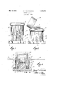
- Figure 1 is an elevation of my device showing the switch in the on position and the fuse receptacle closed.
- Figure 2 is an elevation of my device with the fuse receptacle open, the switch being in the off position.
- Figure 3 is a sectional view of my device.
- I provide, in the exemplary embodiment of .my device, a base 1 of insulating material,
- the column has about its upper edge a flange 3 which extends outwardly for a purpose presently to be described; and the column is hollowed out centrally as at at to accommodate a fuse receptacle, of which 5 indicates the screw socket and 6 the central contact screw.
- these contact members move into or out of a position to close the circuit between the pairs of contact members upon the column and upon the base, and it will be clear that the col lar and its contact members form a switch, such that the circuit is closed when the collar is moved up as far as it will go, and open when it is moved down as far as it will go.
- Such means may comprise a pin 29 in the collar, riding in a groove 30 in the column.
- the cooperative relation of the cover and collar may be varied in a number of ways, as, for example, making the cover a screw cap, providing means on cover and collar to prevent the rotation of the cover while the collar is upraised, and a spring latch or the like on the column to prevent the raising of the collar. excepting the cover be screwed down tight.
- the operation of the collar may be made rotary instead of sliding, a latch provided on the column to inhibit rotation of the collar when the cover is open, and means on collar and cover to prevent opening the cover when the collar has been rotated to a given position.
- My device as an operating mechanism, is complete as it stands. It may be provided With an individual shield, cover or box to' conceal the terminals and protect the wir' or such a shield may be made as a detachab e part of the base.
- the usual practice will be, however, to place one or more of my devices in a metallic box connected to the meter by the usual metallic wiring shield or neck; and I have indicated in Figure 3 and lid 31 of a box to SIlIIOW the correlation of my device therewit 7 Having thus described my invention, what I claim as new and desire to secure by Letters Patent, is:
- a base having an upstanding central portion bearing a fuse receptacle, a member of insulating material surrounding said base portion and movable with reference thereto, line and load terminals on said base having contact members, contact members on said base portion and connected to said fuse receptacle, and means on said movable member for effecting connections between said contact members whereby the fuse receptacle may be connected in series between said line and load terminals or entirely disconnected therefrom, a cover for said fuse receptacle, said cover and said movable member being disposed so that said circuit cannot be completed excepting said cover be closed.
- a base bearing line and load terminals with contact portions, and also bearing a fuse receptacle with contact portions corresponding to but 1nterspaced from said line and load termmal contact portions, an insulating movable member surrounding said fuse receptacle and movable in connection therewith, said member bearing metallic contact portions to complete a circuit wherein said line and load terminals and said fuse receptacle are in series, a cover for said fuse receptacle, said cover and said moving member being so disposed that when said moving member is in a position to effect the closing of said circuit, said moving member will lie in the path of said cover in opening, so as to prevent the opening thereof.
- a base having an upstanding central portion bearing a fuse receptacle, an insulating collar surrounding said fuse receptacle and movable with relation thereto, contact members on the central portion of said base connected with said fuse receptacle, line and load terminals on said base having contact members located adjacent the respective contact members of said fuse receptacle, but separated therefrom by said collar, and metallic members on said collar adapted to effect in one position electrical connection between said contact members respectively so that said fuse receptacle is placed in series with said line and load terminals.
- a base having an upstanding central portion bearing a fuse receptacle, an insulating collar surrounding said fuse receptacle and movable with relation thereto, contact members on the central portion of said base connected with said fuse receptacle, line and load terminals on said base having contact members located adjacent the respective contact members of said fuse receptacle, but separated therefrom by said collar, and metallic members on said collar adapted to effect in one position electrical connection between said contact members respectively so that said fuse receptacle is placed in series with said line and load terminals, a cover for said fuse receptacle, said cover and said collar so disposed that said cover may not be opened excepting said collar be in a position to break the circuit between said contact members, and so that said collar may not be moved to complete said circuit except said cover be closed.
- a base of insulating material having a central column bearing a fuse receptacle with exposed contact members, line and load terminals on said base, having contact members corresponding to said fuse receptacle contact members, a collar of insulating material surrounding said column and separating said contact members, metallic members on said collar to effect a connection between said contact members respectively so as to place said fuse receptacle in electrical series with said line and load terminals, when said collar is in upraised position, a cover hinged to said column and adapted to open when said collar is in depressed position, said collar adapted to surround said cover when in upraised position so as to prevent the opening thereof.
- a base of insulating material bearing a fuse receptacle with contact members, and line and load terminals with contact members and a double break switch adapted to make or break a series circuit between said terminals and through said receptacle, whereby said receptacle may be disconnect-ed from both terminals, and means rotatable through a limited arc of movement to prevent access to said fuse receptacle when said circuit is made.
Landscapes
- Fuses (AREA)
- Switch Cases, Indication, And Locking (AREA)
Description
y 3, 1932- G. E. WADSWORTH 1,856,853
ELECTRICAL DEVICE Filed June 4, 1929 I N V EN TOR.
ATTORNEY5 Patented May 3, 1932 UNITED STATES PATENT OFFICE GEORGE E. WADSWORTH, OF ERLANGER, KENTUCKY, ASSIGNOR, BY MESNE ASSIGN- MENTS, TO THE GEORGE B. WADSWORTH COMPANY, OF GIN CINNA'II, OHIO, A COR- PORATION OF OHIO ELECTRICAL DEVICE Application filed June 4, 1929. Serial No. 368,245.
: used with one for the protection and concealment of the wiring. In such a structure, one of my objects is to provide safety means such that the fuse receptacle and other live parts cannot be got at while the switch is on, nor
can the switch be turned on while such parts are exposed.
It is a further object of my invention to provide a structure of this class which is cheap and easy to manufacture, which is not liable to maladjustment, and in which the working as well as stationary parts have been reduced to a minimum.
It is still a further object of my invention to provide in a device of this class a double break switch adapted to isolate the fuse receptacle from both the line and load terminals, so that during the operation of re-fusmg, the parts exposed will be completely dead.
It is still a further object of my invention to provide a very direct cooperation between the switch operating means and the cover of the fuse receptacle, so that interconnecting levers, cams and the like are eliminated and so that the switch operating means is directly the means permitting or inhibiting the action of the fuse receptacle cover.
These and other objects of my invention, which will be pointed out hereinafter or will be apparent to one skilled in the art upon reading this specification, I accomplish by that certain construction and arrangement of parts of which I shall now describe a preferred embodiment, reference being had to the drawings which accompany this specification.
In the drawings:
Figure 1 is an elevation of my device showing the switch in the on position and the fuse receptacle closed.
Figure 2 is an elevation of my device with the fuse receptacle open, the switch being in the off position.
Figure 3 is a sectional view of my device.
I provide, in the exemplary embodiment of .my device, a base 1 of insulating material,
from which extends a cylindrical shaft or v column 2. The column has about its upper edge a flange 3 which extends outwardly for a purpose presently to be described; and the column is hollowed out centrally as at at to accommodate a fuse receptacle, of which 5 indicates the screw socket and 6 the central contact screw.
Upon opposite sides of the cylindrical column 2 are located metallic contact surfaces or plates 8 and 9 which connect by means of metal straps 10 and 11 respectively to the contact screw 6 and the screw socket 5. Thus an electrical circuit may be established between contact members 8 and 9 through the fuse 7 The contact members are located near the top of the column, so that considerable space is left between them and the base 1.
About the column I place a collar 12, also of insulating material, having an upper enlarged portion 13 of such configuration as will make it convenient for manipulation, and having a lower thickened portion set ofi' by a sharp internal shoulder 14:. It will be noticed that the inside diameter of the collar is for the most of its length sufliciently large to ride over the flange 3; but the portion 15 is smaller than 3, for which reason the movement of the collar up and down over the column is limited. The column 2 is of course, made separate from the base 1, and when the several parts are assembled in the relationship shown, the collar can only move upwardly until the shoulder 14 strikes the flange.
Upon the base, in alignment with the contact members 8 and 9, I position other contact members 16 and 17, upheld by metallic spring straps 18 and 19 fastened to the base, as will be well understood, and bearing tenninal connectors 20 and 21. The line and load leads are connected to these terminals, and I provide means whereby contact members 8 and 16, and 9 and 17 may be connected together, thus closing a fused circuit between the terminals, the said means being adapted to serve as a switch.
I mount cooperating pairs of contact members 22, 23 and 24:, 25, connected respectively by straps, rods or bolts 26 and 27, upon the collar 12. As the collar is moved up or down,
these contact members move into or out of a position to close the circuit between the pairs of contact members upon the column and upon the base, and it will be clear that the col lar and its contact members form a switch, such that the circuit is closed when the collar is moved up as far as it will go, and open when it is moved down as far as it will go.
I now provide means whereby the collar controls the accessibility of the fuse receptaole, such that when the switch is closed the receptacle will be inaccessible, and when the switch is open the circuit cannot be closed until the fuse receptacle is again covered. A number of ways of doing this will be within the purview of those skilled in the art to construct without departing from the spirit of 'my invention, and the means described are vide a cover 28, cylindrical in shape, closed at the top, but hollow within to accommodate the top of the fuse 7, and of an outside diameter substantially the same as the outside diameter of the flange 3. This cover, I
hinge to the flange as at 29, so that, when the collar has been depressed, it may swing upwardly as shown in Figure 2 and expose the fuse. It will be clear that when the collar is in uprafsed position, as in Figure 1, the cover 28 cannot be raised, and further that the collar cannot be raised excepting the cover be closed. This construction gives the desired safety features in my device. The collar, when upraised, completes the electrical circuit and locks the fuse receptacle cover. So long as the cover is open, the switch mechanism cannot be moved to the closed position. So long as the cover is closed, the switch may be in either on or off position, but the cover cannot be opened excepting the switch be in the off position. When the switch is off, and the cover raised, the fuse receptacle parts are dead, being cut off from both line and load terminals.
So that the movement of the collar may be controlled to the end that the contact members may be always in alignment, I provide means for preventing such a rotation of the collar as would bring them out of alignment. Such means may comprise a pin 29 in the collar, riding in a groove 30 in the column.
Modifications may be made in my device without departing from my invention. The cooperative relation of the cover and collar may be varied in a number of ways, as, for example, making the cover a screw cap, providing means on cover and collar to prevent the rotation of the cover while the collar is upraised, and a spring latch or the like on the column to prevent the raising of the collar. excepting the cover be screwed down tight. Or the operation of the collar may be made rotary instead of sliding, a latch provided on the column to inhibit rotation of the collar when the cover is open, and means on collar and cover to prevent opening the cover when the collar has been rotated to a given position.
My device, as an operating mechanism, is complete as it stands. It may be provided With an individual shield, cover or box to' conceal the terminals and protect the wir' or such a shield may be made as a detachab e part of the base. The usual practice will be, however, to place one or more of my devices in a metallic box connected to the meter by the usual metallic wiring shield or neck; and I have indicated in Figure 3 and lid 31 of a box to SIlIIOW the correlation of my device therewit 7 Having thus described my invention, what I claim as new and desire to secure by Letters Patent, is:
1. In an electrical device a support of insulating material bearing a fuse receptacle,
terminals on said fuse receptacle, line and load terminals on said support and means for effecting a connection between the line terminal and one of said fuse terminals and between the load terminal and one of said fuse terminals, said means being rotatable through a limited arc of movement to make or break the said contact, and comprising a member of insulating material bearing contact effecting means, and mounted. on the portion of said support containing said fuse receptacle, and being movable with relation thereto.
2. In an electrical device a support of insulating material bearing a fuse receptacle, terminals on said fuse receptacle, line and load terminals on said support and means for effecting a connection between the line terminal and one of said fuse terminals and between the load terminal and one of said fuse terminals, said means being rotatable through a limited arc of movement to make or break the said contact, and comprising a member of insulating material bearing contact efi'ecting means, and mounted on the portion of said support containing said fuse receptacle, and being movable with relation thereto, a cover to prevent access to said receptacle and means interrelating said cover and said contact means whereby the circuit cannot be closed when said cover is open and said cover 4. In an electrical device a base having an upstanding central portion bearing a fuse receptacle, a member of insulating material surrounding said base portion and movable with reference thereto, line and load terminals on said base having contact members, contact members on said base portion and connected to said fuse receptacle, and means on said movable member for effecting connections between said contact members whereby the fuse receptacle may be connected in series between said line and load terminals or entirely disconnected therefrom, a cover for said fuse receptacle, said cover and said movable member being disposed so that said circuit cannot be completed excepting said cover be closed.
5. In an electrical device, a base bearing line and load terminals with contact portions, and also bearing a fuse receptacle with contact portions corresponding to but 1nterspaced from said line and load termmal contact portions, an insulating movable member surrounding said fuse receptacle and movable in connection therewith, said member bearing metallic contact portions to complete a circuit wherein said line and load terminals and said fuse receptacle are in series, a cover for said fuse receptacle, said cover and said moving member being so disposed that when said moving member is in a position to effect the closing of said circuit, said moving member will lie in the path of said cover in opening, so as to prevent the opening thereof.
6. In an electrical device a base bearing line and load terminals with contact members, and a central upstanding portion bearing a fuse receptacle, a collar of insulating material surrounding the said upstanding portion, contact members on said base portion connected with said fuse receptacle and means on said collar to effect the connection of said contact members with the contact members on said line and load terminals, said collar thus adapted to act as the operating means for a switch, a cover on said fuse receptacle, said cover and collar so disposed as to control the movement of each by the other.
7. In an electrical device, a base bearing line and load terminals and an upstanding portion bearing a fuse receptacle, a collar movable about said upstanding portion and bearing means to effect an electrical connection between said fuse receptacle and said line and load terminals by an upward movement, a cover mounted upon said fuse receptacle and adapted to be held against opening by the upward movement of said collar.
8. In an electrical device, a base having an upstanding central portion bearing a fuse receptacle, an insulating collar surrounding said fuse receptacle and movable with relation thereto, contact members on the central portion of said base connected with said fuse receptacle, line and load terminals on said base having contact members located adjacent the respective contact members of said fuse receptacle, but separated therefrom by said collar, and metallic members on said collar adapted to effect in one position electrical connection between said contact members respectively so that said fuse receptacle is placed in series with said line and load terminals.
9. In an electrical device, a base having an upstanding central portion bearing a fuse receptacle, an insulating collar surrounding said fuse receptacle and movable with relation thereto, contact members on the central portion of said base connected with said fuse receptacle, line and load terminals on said base having contact members located adjacent the respective contact members of said fuse receptacle, but separated therefrom by said collar, and metallic members on said collar adapted to effect in one position electrical connection between said contact members respectively so that said fuse receptacle is placed in series with said line and load terminals, a cover for said fuse receptacle, said cover and said collar so disposed that said cover may not be opened excepting said collar be in a position to break the circuit between said contact members, and so that said collar may not be moved to complete said circuit except said cover be closed.
10. In an electrical apparatus, a base of insulating material having a central column bearing a fuse receptacle with exposed contact members, line and load terminals on said base, having contact members corresponding to said fuse receptacle contact members, a collar of insulating material surrounding said column and separating said contact members, metallic members on said collar to effect a connection between said contact members respectively so as to place said fuse receptacle in electrical series with said line and load terminals, when said collar is in upraised position, a cover hinged to said column and adapted to open when said collar is in depressed position, said collar adapted to surround said cover when in upraised position so as to prevent the opening thereof.
11. In a fused switch device, a base of insulating material bearing a fuse receptacle with contact members, and line and load terminals with contact members and a double break switch adapted to make or break a series circuit between said terminals and through said receptacle, whereby said receptacle may be disconnect-ed from both terminals, and means rotatable through a limited arc of movement to prevent access to said fuse receptacle when said circuit is made.
GEORGE E. WADSWORTH.
Priority Applications (1)
| Application Number | Priority Date | Filing Date | Title |
|---|---|---|---|
| US368245A US1856858A (en) | 1929-06-04 | 1929-06-04 | Electrical device |
Applications Claiming Priority (1)
| Application Number | Priority Date | Filing Date | Title |
|---|---|---|---|
| US368245A US1856858A (en) | 1929-06-04 | 1929-06-04 | Electrical device |
Publications (1)
| Publication Number | Publication Date |
|---|---|
| US1856858A true US1856858A (en) | 1932-05-03 |
Family
ID=23450454
Family Applications (1)
| Application Number | Title | Priority Date | Filing Date |
|---|---|---|---|
| US368245A Expired - Lifetime US1856858A (en) | 1929-06-04 | 1929-06-04 | Electrical device |
Country Status (1)
| Country | Link |
|---|---|
| US (1) | US1856858A (en) |
-
1929
- 1929-06-04 US US368245A patent/US1856858A/en not_active Expired - Lifetime
Similar Documents
| Publication | Publication Date | Title |
|---|---|---|
| US1856858A (en) | Electrical device | |
| US3179762A (en) | Enclosed electrical switchgear with protective hinged access cover | |
| US2255470A (en) | Switching apparatus | |
| US1700437A (en) | Locking plug switch | |
| US1699753A (en) | Switch mechanism | |
| US1782594A (en) | Electric switch gear | |
| US2636929A (en) | Housing for electrical components | |
| US1804724A (en) | Fusible switch mechanism | |
| US1656383A (en) | Safety switch | |
| US1785290A (en) | Safety electrical device | |
| US1652795A (en) | X i inclosed switch | |
| US1974154A (en) | Lighting panel and unit therefor | |
| US1237370A (en) | Cut-out switch. | |
| US1766526A (en) | Electric switch | |
| US1347345A (en) | lofgren | |
| US1306343A (en) | Hubert f | |
| US868387A (en) | Apparatus for inclosing and electrically connecting miners' safety-lamps to effect electric ignition. | |
| US1972245A (en) | Switch box | |
| US2501569A (en) | Electric connection device | |
| US1747035A (en) | Electrical switch | |
| US1545614A (en) | Switch-housing structure | |
| US1619640A (en) | Explosionproof fuse | |
| US1712768A (en) | Automatic cut-out pulley | |
| US1574996A (en) | Fuse-switch mechanism | |
| US1737235A (en) | Switch box |