US1856855A - Feeding mechanism for slicing machines - Google Patents
Feeding mechanism for slicing machines Download PDFInfo
- Publication number
- US1856855A US1856855A US12063526A US1856855A US 1856855 A US1856855 A US 1856855A US 12063526 A US12063526 A US 12063526A US 1856855 A US1856855 A US 1856855A
- Authority
- US
- United States
- Prior art keywords
- feed
- guide
- rib
- under table
- under
- Prior art date
- Legal status (The legal status is an assumption and is not a legal conclusion. Google has not performed a legal analysis and makes no representation as to the accuracy of the status listed.)
- Expired - Lifetime
Links
- 230000033001 locomotion Effects 0.000 description 23
- 235000013372 meat Nutrition 0.000 description 23
- 238000006073 displacement reaction Methods 0.000 description 3
- 239000013589 supplement Substances 0.000 description 3
- 229910000792 Monel Inorganic materials 0.000 description 1
- 238000009825 accumulation Methods 0.000 description 1
- 238000010276 construction Methods 0.000 description 1
- 238000012840 feeding operation Methods 0.000 description 1
- 239000000463 material Substances 0.000 description 1
- 239000002184 metal Substances 0.000 description 1
- 230000009972 noncorrosive effect Effects 0.000 description 1
- 230000010355 oscillation Effects 0.000 description 1
- 230000001681 protective effect Effects 0.000 description 1
- 239000004576 sand Substances 0.000 description 1
- 210000002832 shoulder Anatomy 0.000 description 1
Images

Classifications
-
- B—PERFORMING OPERATIONS; TRANSPORTING
- B26—HAND CUTTING TOOLS; CUTTING; SEVERING
- B26D—CUTTING; DETAILS COMMON TO MACHINES FOR PERFORATING, PUNCHING, CUTTING-OUT, STAMPING-OUT OR SEVERING
- B26D7/00—Details of apparatus for cutting, cutting-out, stamping-out, punching, perforating, or severing by means other than cutting
- B26D7/06—Arrangements for feeding or delivering work of other than sheet, web, or filamentary form
- B26D7/0616—Arrangements for feeding or delivering work of other than sheet, web, or filamentary form by carriages, e.g. for slicing machines
-
- Y—GENERAL TAGGING OF NEW TECHNOLOGICAL DEVELOPMENTS; GENERAL TAGGING OF CROSS-SECTIONAL TECHNOLOGIES SPANNING OVER SEVERAL SECTIONS OF THE IPC; TECHNICAL SUBJECTS COVERED BY FORMER USPC CROSS-REFERENCE ART COLLECTIONS [XRACs] AND DIGESTS
- Y10—TECHNICAL SUBJECTS COVERED BY FORMER USPC
- Y10T—TECHNICAL SUBJECTS COVERED BY FORMER US CLASSIFICATION
- Y10T74/00—Machine element or mechanism
- Y10T74/15—Intermittent grip type mechanical movement
- Y10T74/1526—Oscillation or reciprocation to intermittent unidirectional motion
- Y10T74/1553—Lever actuator
- Y10T74/1555—Rotary driven element
-
- Y—GENERAL TAGGING OF NEW TECHNOLOGICAL DEVELOPMENTS; GENERAL TAGGING OF CROSS-SECTIONAL TECHNOLOGIES SPANNING OVER SEVERAL SECTIONS OF THE IPC; TECHNICAL SUBJECTS COVERED BY FORMER USPC CROSS-REFERENCE ART COLLECTIONS [XRACs] AND DIGESTS
- Y10—TECHNICAL SUBJECTS COVERED BY FORMER USPC
- Y10T—TECHNICAL SUBJECTS COVERED BY FORMER US CLASSIFICATION
- Y10T83/00—Cutting
- Y10T83/647—With means to convey work relative to tool station
- Y10T83/6492—Plural passes of diminishing work piece through tool station
- Y10T83/6499—Work rectilinearly reciprocated through tool station
- Y10T83/6508—With means to cause movement of work transversely toward plane of cut
- Y10T83/6515—By means to define increment of movement toward plane of cut
- Y10T83/6536—By carriage
Definitions
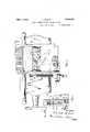
- FIG. 1 is a top plan view of the feeding mechanism of a slicing machine embodying the present invention
- Fig. 2 is an elevation of the mechanism shown in Fig. 1; V
- Fig. 3 is a section on line 3-3 of Fig. 2;
- Fig. 4 isa fragmentary section showing the spring plate construction
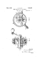
- Fig. 5 is a vertical section through the ratchet feed mechanism
- Fig. 6 is a section on line 66 of Fig. 5;
- Fig. 7 is a fragmentary top plan of a portion of the feed table.
- Figs. 1 and 2 of the drawings designates the supporting base or frame of a slicing machine having a hand crank 11 secured to a shaft 12 and geared to an upright spindle 13 which rotates the main drive crank 14 in the usual manner.
- a reciprocating under table 15 is guided on ways 16 on the base 10 and is connected-to the crank 1 1 by a connecting rod 17.
- a feed lever 18 is pivotally mounted on a post 19 extending downwardly from the under table and provided with a spring friction device 20 to prevent noise and: lost motion.
- a roller 21 is carried by the connecting rod 17 and travels in a cam groove 22 in the feed lever 18. It
- the connecting rod 17 will have an oscillating movement about its pivota1 connection 23 with the under table 15 due to the rotation of the crank arm 14:.
- the oscillation of the connecting rod 17 about its pivotal point 23 will move the roller 21 in the cam groove 22 and this groove is provided with a portion at each end arranged concentric with the pivot 23 when the roller 21 is in'the' end portions and is also provided with an eccentric portion between the ends which will impart pivotal movement of the lever about its support 19.
- the groove is so shaped that the pivotal movement of the lever 18 will take place at the ends ofthe reciprocating travel of the under table.
- the end of the lever 18 opposite the cam groove 22 is connected by a link 24 with a rack bar 25 which slides in a guide 26 on the under table.
- the bar '25 extends into a ratchet housing 27 also fixed to the under table adjacent the operators side.
- a guide block 28 which engages the under face ofthe rack bar 25 and holds the teeth 29 of the rack bar in mesh with the teeth 30 of a gear segment 31.
- 'An adjustment screw 32 is threaded in a boss 33 formedon the case 27 by means of which the slide block 28 which may be adjusted upwardly to take up any play or lost motion between the gear teeth29 and 3 0.
- a set screw'34 may be provided to lock the adjusting screw 32 in its adjusted positions.
- the link 21 is adjustably connected to the rack 25 by means of a connecting yoke and lock nut, shown in Fig. 1. If the rack, pinion, or pawl and ratchet mechanism becomes worn so that the slicesdo not conform in thickness to the adjustment of the indicator as determined by the detent fall 57, the error can be remedied by adjustment of the rack 25 relative to the link 24.
- the gear segment 31 is provided with an arm 35 having a pawl 36 pivoted at 37 thereon.
- the gear segment 31 is loose on a shaft 38 journaled in a bearing 39 carried by the housing 27.
- A'ratche't wheel 40 is fixed to the shaft 38 and provided with teeth 41 in position to be engaged by the pawl 36.
- the arm 35 is 'providedwith a recessed lug 42 which contains a spring 43 arranged to engage a pin 44 on the tail of the pawl 36 to urge the nose 45 of the pawl into engagement with the ratchet teeth 41.
- the housing 27 is provided with a cover plate 46 which is journaled on a projection 47 formed on the ratchet wheel 40.
- the cover plate 46 is held in place by a hand crank 48 removably secured to the shaft 38 by a pin 49.
- the cover plate 46 is provided on its inner side with a cam or shroud 50 arranged to engage a roller 51 secured to the pawl 36.
- the cam 50 when engaged by the roller 51 holds the nose 45' out of engagement with the teeth 41.
- the position of the cam 50 may be adjusted by rotating the cover plate 46 about the supporting bearing 47.
- the cover plate 46 is pro vided with a handle 52 for rotating the cover plate to adjust the cam 50 and the cover plate is provided with a portion 53 which overlaps the side wall of the casing 27.
- An index plate 54 is secured to the overlapping portion 53 of the cover plate and is provided with graduations, shown in Fig. 2, which cooperate with a pointer 56 to indicate the position of the shroud 50.
- a ball detent 57 is mounted in an opening 58 in the case 27 and is pressed outwardly by a spring 59 to engage spaced openings 60 in the overlapping flange 53 of the plate 46.
- the openings 60 are spaced to correspond to graduations on the plate 54 so as to releasably hold the plate 46in its different positions of adjustment corresponding to the graduations.
- the handle 52 is in its lowermost position in which the roller 51 travels on the cam50 throughout the entire range of move ment of the pawl 36. In this position the pointer 56 indicates zero on thc'graduated plate 54. As the handle 56 is raised the cam 50 will be termed in a clockwise direction, as viewed in Fig.
- the rack will remain stationary during the movement of the table. past the edge of the knife and will be returned at the end of the movement of the table opposite the operators position.
- the meat plate or table 65 slides upon the under table 15 in a direction transverse to the direction of reciprocation of the under table.
- the under table is provided with a narrow guide or rib 66 at the edge thereof adjacent the operators position and the meat'table 65 is provided with .a co-operatingguide rib 67.
- the contact faces of the ribs 66 and 67 are preferably inclined as shown in Fig. 3, to hold the meat table against, upward movement.
- the edge of the under table'15 opposite the rib 66 is provided with a flat bearing face 68 on which a downwardly projecting rib 69 of the meat table slides.
- a retainer plate 70 is secured to the edge of the under table and carries a flange 71 which fits loosely intothe groove of the rib 69.
- the flange 71 is merely-for the purpose of preventing displacement of the meat table upwardly and does not act as a guide for the table, but travels loosely in the groove formed in the rib 69.
- the meat table 65' is guided entirely by the narrow rib 66 which is engaged at one side by the rib 67 and at the opposite side by a spring plate 72 secured to the side of the meat table 65 by screws 7 3, theheads table may be made much shorter without danger of binding than can be done where the guides are disposed at oppositesides of the meat table.
- the spring plate '7 2 serves to draw the inclined edges of the ribs 66 and 67 together to hold. the meat table against upward displacement and at the same time furnishesa frictionalresistance to prevent overthrow of the meat table when operated by the feed screw.
- the feed screw 75 is formed on the shaft .38 which is journaled in the ratchet housing 27 and a bearing 76 secured to the under table.
- a spring 77 is arranged-in the bearing 76 to exert pressure on the endof thefeed screw in the direction of the length thereof to maintain the feed screw in its rearmost position, thus preventing any lost'motion in the movement of the meat table due to longitudinal movement of the feed screw;
- the meat table 65 is releasably connected with the feed screw by means of a segmental nut or toothed nut 78 into engagement with the screw by means of a spring 82 disposed in a recess in the side of the meat table 65 and arranged to press a ball 83 against the bracket 79, as shown in Fig.
- the bracket 791 is provided with a handle 84 by means of which it may be lifted to disengage the segmental nut 78 from the screw 75.
- the shaft carries cams 88 which bear against the spring plate 7 2, as shown in Fig. 4, in position to compress the spring 74 and release the spring plate when the handle 8-1 is raised, thus freeing the table of frictional resistance to movement along the guide rib 66. This will also permit the table to move to the right, as viewed in Fig.
- the meat table 65 is covered by a plate 85 of non-corrosive sheet metal, such as Monel metal.
- This plate overlaps the top edge of the spring plate 72 preventing the accumulation of foreign material behind the spring plate in such a way as to interfere with its operation.
- the plate may also extend over the feed screw, as shown, to form a protective cover for the screw. 7
- segmental nut 78 engages the outer side of the screw 75 and presses inwardly against the screw so that the spring pressure of the nut supplements the pressure of the plate 7 2 in holding the inclined faces of the guide ribs 66 and 67 in close .contact with each other.
- the support for the bearing 76 extends along the inside of the screw 75, as shown in F ig. 1, and is preferably providedwith a curved flange 86" shown in Fig. 3 covering the screw 75.
- I claim r l 1.
- an under table having a narrow guide rib at one edge thereof and a flat bearing surface at the opposite edge thereof, a meat table having a guide face engaging one side of said guide rib and having a support engaging said bearing surface, a spring plate secured to said meat table and engaging the side of the narrow guide rib on said under table opposite that engaged by the guide on saidmeat table,-said guide rib and spring plate being disposed at the side of the under table adjacent the operators side of the machine, and means onthe operators side of the machine for moving the meat table.
- an under table a feed table mounted to slide on said undertable.
- a narrow guide rib at one edge of said under table having an overhanging guide face at one side thereof, said feed table having a guide face inclined to fit the overhanging said inclined guide face, the edge of said feed table opposite said guide rib being free to slide on said under table both in the direction of feed of said feed table and in a direction transverse thereto except as restrained by said guide rib, and means on the side of said table adjacent said guide rib for moving said table.
- an under table having a narrow guide rib at the edge thereof adjacent the operators side of the machine and a flat bearing face at the opposite edge thereof, the inner surface of said guide rib being inclined to provide an overhanging portion, a feed table mountedon said under table and provided with a rib'at one side thereof having an inclined face to fit the inclined face of the guide rib on said under table, the side of said feed table opposite said guide ribs being arranged toslideon said under table, means for holding said opposite edge from vertical displacement from said under table while permitting lateral and iongitudinal movement thereof, and a spring plate secured to said feed table in position to engage the outer face of the guide rib on said under table. 4.
- an under table having a narrow guide rib thereon adjacent the operators side of the machine, a feed table mounted on said under table and having an inclined guide face arranged to engage an inclined guide face on the rib on said under table, a spring plate secured to said feed table and-projecting downwardly to engage the face of said guide rib opposite the inclined face thereof, and means for covering the space between said spring plate and said feed table at theupper edge of said spring plate.
- an under table having a narrow guide rib at the edge thereof adjacent the operators side of the ma chine provided with an inner'overhanging guide face and an outer verticalguide face
- a feed table mounted onsaid under table and having an inclined guide face arranged to engage the inclined guide face of the rib on said under table andhaving a spring plate arranged to engage.
- the vertical guide plate on the rib of said under table means for movement thereof, and a handle secured to said'feed ta le at the same side thereof as.
- saidguide rib to facilitate lateralpressure on said feed table against the tension of said I spring plate to free said inclined guide faces and permit removal of said feed table from said under table.
- an under table having a narrow guide rib at the edge thereof adjacent the operators side of the machine, a feed screw mounted on said under table adjacent said narrow guide rib and parallel therewith, a feed table mounted on said under table and having a guide surface engagmg one side of sand guide Ilb' and a spring plate engaging the opposite side of said guide rib, a segmental nut arranged to engage said feed screw at one side thereof, a plvoted bracket for supporting said nut on said feed table, an d a spring for exerting pressure on said nut to hold said nut in engagement-with said feed screw andto supplement the action of said spring plate in drawing the guide face on said feed table against the guide face of the rib on said under table.
- a reciprocating under table having a guide rib extending along the edge thereof adjacent the operators position of said slicing machine, a feed screw 'journaled on said under table parallel with sald guide rib and ad acent thereto on the side ofthe under table next to the operators side of the slicing machine, a feed table mounted to slide on said under table and having a guide face arranged to engage one face of said guide rib and having a spring plate arranged to engage the opposite face of said guide rib, the engaging guide faces on said guide rib and feed table being inclined-to resist upward movement of said feed table from said under table, a feed nut support mounted on said feed table and having a feed nut carried thereby and resiliently pressed against'the side of said feed screw opposite said guide rib so that the pressure thereon supplements the pressure of said spring plate in drawing said inclined guide faces together, and a handle located at the side of the feed table next to the operators side of the slicing machine and connected with said feed nut
- an under table a feed table slidably mounted on said under table, a spring-pressed friction plate mounted on said feed table at the side thereof adj acent the operators side of the slicing machine and engaging said under table to control the sliding movement of said feed table on said under table, a feed screw mounted on said under table at the side thereof adjacent said friction plate, a shaft journaled on said feed table, a bracket secured to said shaft, a segmental nut carried by said brackets for engaging said feed screw, a handle for rotating said shafttodisengage said nut from said feed screw,'and means secured to said shaft for engaging said sprlng frictlon plate to release said plate simultaneously with the disengagement of said nut from said feed 9.
- an under table having a narrow guide rib at the edge thereof adjacent the operators side of the slicing machine provided with an overhanging inner guide face
- a feed table slidably mounted on said under table and having a guide surface for engaging said guide face
- a spring plate mounted on said feed table for engaging said guide rib at the side thereof opposite said inclined guide face
- a feed screw journaled on said under table at the side thereof adjacent said guide rib
- a bracket pivotally mounted on said feed table, a segmental nut carried by said bracket for engaging said feed screw, a handle for movingsaid bracket to release said nut from said feed screw, and means operated by said handle to release said spring plate
- said feed table being movable away from the guide face on saidguide rib by pressure on said handle in a direction to release said segmental nut from said feed screw.
- an under table a feed table slidably mounted on said'under table, a feed screw mounted on said under table at the operators side thereof, and a cover plate extending downwardly from said under table over said feed screw.
- a slicing machine having a reciprocatory undertable and a meat table movable transversely thereof, a feed screw, a housing within which one end of said feed screw is journalled, said housing being formed of a stationary section ri id with said undertable, and a section rotata ly connected with said stationary section, a gear loosely mounted on said feed screw, a ratchet rigid with said feed screw, a pawl carried by said gear for engaging said ratchet, a ratchet shield on said rotatable housing section, said gear, ratchet, pawl and shield being enclosed in said housing, a rack meshing with said gear, and means associated with said slicing machine for 1imparting reciprocatory movement to said rac 12.
- a feed screw In a slicing machine having a reciprocatory undertable and a meat table movable transversely thereof, a feed screw, a housing within which one end of said feed screw is j ournalled,said housing being formed of astationary section rigid with said undertable, and a section rotatably connected with said stationary section, feeding mechanism inclosed within said housing includinga ratchet and a shield carried on said rotatable section, a
Landscapes
- Life Sciences & Earth Sciences (AREA)
- Forests & Forestry (AREA)
- Engineering & Computer Science (AREA)
- Mechanical Engineering (AREA)
- Transmission Devices (AREA)
Description
May 3, 1932. STUKART 1,856,855
FEEDING MECHANISM FOR SLICING MACHINES Fi y 1926 3 Sheets-Sheet l May 3, 1932. H. STUKART I FEEDING MECHANISM FOR SLICING MACHINES Filed July 6, 1926 5 Sheets$heet MR RM NR N mm mv FEEDING MECHANISM FOR SLICING MACHINES Filed July 6, 1 926- 3 Sheets-Sheet 3 g v Q Patented May 3, 1932 UNITED STATES PATEN oFFicE HENDRIX STUKART, OF LA FORTE, INDIANA, ASSIGNOR TO U. S. SLICING MACHINE COMPANY, OF LA PORTE, INDIANA, A CORPORATION OF INDIANA FEEDING MECHANISM FOR SLICING MACHINES Application filed my e, 1926. Serial No. 120,635.
1 and in which improved mechanism is provided for feeding the table along its guiding mechanism.
Other objects and advantages will appear in the following description.
The invention is exemplified in the combination and arrangement of parts shown in the accompanying drawings and described in the following specification, and it is more particularly pointed out in the appended claims.
In the drawings Fig. 1 is a top plan view of the feeding mechanism of a slicing machine embodying the present invention;
Fig. 2 is an elevation of the mechanism shown in Fig. 1; V
Fig. 3 is a section on line 3-3 of Fig. 2;
Fig. 4 isa fragmentary section showing the spring plate construction;
Fig. 5 is a vertical section through the ratchet feed mechanism;
Fig. 6 is a section on line 66 of Fig. 5; and
Fig. 7 is a fragmentary top plan of a portion of the feed table.
In Figs. 1 and 2 of the drawings the numeral 10 designates the supporting base or frame of a slicing machine having a hand crank 11 secured to a shaft 12 and geared to an upright spindle 13 which rotates the main drive crank 14 in the usual manner. A reciprocating under table 15 is guided on ways 16 on the base 10 and is connected-to the crank 1 1 by a connecting rod 17. A feed lever 18 is pivotally mounted on a post 19 extending downwardly from the under table and provided with a spring friction device 20 to prevent noise and: lost motion. A roller 21 is carried by the connecting rod 17 and travels in a cam groove 22 in the feed lever 18. It
is apparent that the connecting rod 17 will have an oscillating movement about its pivota1 connection 23 with the under table 15 due to the rotation of the crank arm 14:. 'The oscillation of the connecting rod 17 about its pivotal point 23 will move the roller 21 in the cam groove 22 and this groove is provided with a portion at each end arranged concentric with the pivot 23 when the roller 21 is in'the' end portions and is also provided with an eccentric portion between the ends which will impart pivotal movement of the lever about its support 19. The groove is so shaped that the pivotal movement of the lever 18 will take place at the ends ofthe reciprocating travel of the under table. The end of the lever 18 opposite the cam groove 22 is connected by a link 24 with a rack bar 25 which slides in a guide 26 on the under table. The bar '25, as shown in Figs. 5 and 6, extends into a ratchet housing 27 also fixed to the under table adjacent the operators side. Within the housing 27 is. a guide block 28 which engages the under face ofthe rack bar 25 and holds the teeth 29 of the rack bar in mesh with the teeth 30 of a gear segment 31. 'An adjustment screw 32 is threaded in a boss 33 formedon the case 27 by means of which the slide block 28 which may be adjusted upwardly to take up any play or lost motion between the gear teeth29 and 3 0. A set screw'34 may be provided to lock the adjusting screw 32 in its adjusted positions.
The link 21 is adjustably connected to the rack 25 by means of a connecting yoke and lock nut, shown in Fig. 1. If the rack, pinion, or pawl and ratchet mechanism becomes worn so that the slicesdo not conform in thickness to the adjustment of the indicator as determined by the detent fall 57, the error can be remedied by adjustment of the rack 25 relative to the link 24.
The gear segment 31 is provided with an arm 35 having a pawl 36 pivoted at 37 thereon. The gear segment 31 is loose on a shaft 38 journaled in a bearing 39 carried by the housing 27. A'ratche't wheel 40 is fixed to the shaft 38 and provided with teeth 41 in position to be engaged by the pawl 36. The arm 35 is 'providedwith a recessed lug 42 which contains a spring 43 arranged to engage a pin 44 on the tail of the pawl 36 to urge the nose 45 of the pawl into engagement with the ratchet teeth 41. The housing 27 is provided with a cover plate 46 which is journaled on a projection 47 formed on the ratchet wheel 40. The cover plate 46 is held in place by a hand crank 48 removably secured to the shaft 38 by a pin 49. The cover plate 46 is provided on its inner side with a cam or shroud 50 arranged to engage a roller 51 secured to the pawl 36. The cam 50 when engaged by the roller 51 holds the nose 45' out of engagement with the teeth 41. The position of the cam 50 may be adjusted by rotating the cover plate 46 about the supporting bearing 47. The cover plate 46 is pro vided with a handle 52 for rotating the cover plate to adjust the cam 50 and the cover plate is provided with a portion 53 which overlaps the side wall of the casing 27. An index plate 54 is secured to the overlapping portion 53 of the cover plate and is provided with graduations, shown in Fig. 2, which cooperate with a pointer 56 to indicate the position of the shroud 50.
A ball detent 57 is mounted in an opening 58 in the case 27 and is pressed outwardly by a spring 59 to engage spaced openings 60 in the overlapping flange 53 of the plate 46. The openings 60 are spaced to correspond to graduations on the plate 54 so as to releasably hold the plate 46in its different positions of adjustment corresponding to the graduations. In Fig. 6 of the draw ings, the handle 52 is in its lowermost position in which the roller 51 travels on the cam50 throughout the entire range of move ment of the pawl 36. In this position the pointer 56 indicates zero on thc'graduated plate 54. As the handle 56 is raised the cam 50 will be termed in a clockwise direction, as viewed in Fig. 6, so that when the pawl 36 moves in a counter-clockwise direction the roller 51 will pass from the shoul der 61 and permit the pawl to engage the ratchet teeth 41 and rotate the shaft 38. This Will impart a feeding movement to the meat support, as will be explained later. The amount of movement imparted will depend upon the position of adjustment of the handle 52 and the cam 50, thus producing different thicknesses of slices. .The thickness of the sliceproduced will be indicated by the graduations on the plate 54. The movement of the rack 25 to the right, as viewed in Fig. 6, to produce feeding operation of the meat table will occur at the time when the reciprocating table is at the end of the supporting ways adjacent the operating wheel 11. At this time the table will be free of the rotating knife so that the meat may be fed past;
the edge of the knife into position to be sliced.
The rack will remain stationary during the movement of the table. past the edge of the knife and will be returned at the end of the movement of the table opposite the operators position.
The meat plate or table 65 slides upon the under table 15 in a direction transverse to the direction of reciprocation of the under table. As shown in Fig. 3, the under table is provided with a narrow guide or rib 66 at the edge thereof adjacent the operators position and the meat'table 65 is provided with .a co-operatingguide rib 67. .The contact faces of the ribs 66 and 67 are preferably inclined as shown in Fig. 3, to hold the meat table against, upward movement. The edge of the under table'15 opposite the rib 66 is provided with a flat bearing face 68 on which a downwardly projecting rib 69 of the meat table slides. A retainer plate 70 is secured to the edge of the under table and carries a flange 71 which fits loosely intothe groove of the rib 69. The flange 71 is merely-for the purpose of preventing displacement of the meat table upwardly and does not act as a guide for the table, but travels loosely in the groove formed in the rib 69. As shown in Fig. 4, the meat table 65' is guided entirely by the narrow rib 66 which is engaged at one side by the rib 67 and at the opposite side by a spring plate 72 secured to the side of the meat table 65 by screws 7 3, theheads table may be made much shorter without danger of binding than can be done where the guides are disposed at oppositesides of the meat table. The spring plate '7 2 serves to draw the inclined edges of the ribs 66 and 67 together to hold. the meat table against upward displacement and at the same time furnishesa frictionalresistance to prevent overthrow of the meat table when operated by the feed screw.
The feed screw 75, as shown in Figs. 1 and 3, is formed on the shaft .38 which is journaled in the ratchet housing 27 and a bearing 76 secured to the under table. A spring 77 is arranged-in the bearing 76 to exert pressure on the endof thefeed screw in the direction of the length thereof to maintain the feed screw in its rearmost position, thus preventing any lost'motion in the movement of the meat table due to longitudinal movement of the feed screw; The meat table 65 is releasably connected with the feed screw by means of a segmental nut or toothed nut 78 into engagement with the screw by means of a spring 82 disposed in a recess in the side of the meat table 65 and arranged to press a ball 83 against the bracket 79, as shown in Fig. 3. The bracket 791 is provided with a handle 84 by means of which it may be lifted to disengage the segmental nut 78 from the screw 75. By lifting the handle 84: a suflicient amount to free the nut 78 the table may be shifted by hand along the feed screw 75. The shaft carries cams 88 which bear against the spring plate 7 2, as shown in Fig. 4, in position to compress the spring 74 and release the spring plate when the handle 8-1 is raised, thus freeing the table of frictional resistance to movement along the guide rib 66. This will also permit the table to move to the right, as viewed in Fig. 2, a suflicient distance to clear the overhanging contact faces of the ribs 66 and 67 to permit the table to be lifted from its support, if desired. The meat table 65 is covered by a plate 85 of non-corrosive sheet metal, such as Monel metal. This plate, as shown in Fig. 4, overlaps the top edge of the spring plate 72 preventing the accumulation of foreign material behind the spring plate in such a way as to interfere with its operation. The plate may also extend over the feed screw, as shown, to form a protective cover for the screw. 7
It will be noted from Fig. 3 that the segmental nut 78 engages the outer side of the screw 75 and presses inwardly against the screw so that the spring pressure of the nut supplements the pressure of the plate 7 2 in holding the inclined faces of the guide ribs 66 and 67 in close .contact with each other.
The support for the bearing 76 extends along the inside of the screw 75, as shown in F ig. 1, and is preferably providedwith a curved flange 86" shown in Fig. 3 covering the screw 75.
I claim r l 1. In a meat slicing machine, an under table having a narrow guide rib at one edge thereof and a flat bearing surface at the opposite edge thereof, a meat table having a guide face engaging one side of said guide rib and having a support engaging said bearing surface, a spring plate secured to said meat table and engaging the side of the narrow guide rib on said under table opposite that engaged by the guide on saidmeat table,-said guide rib and spring plate being disposed at the side of the under table adjacent the operators side of the machine, and means onthe operators side of the machine for moving the meat table. p
2. In a slicing machine, an under table, a feed table mounted to slide on said undertable. a narrow guide rib at one edge of said under table having an overhanging guide face at one side thereof, said feed table having a guide face inclined to fit the overhanging said inclined guide face, the edge of said feed table opposite said guide rib being free to slide on said under table both in the direction of feed of said feed table and in a direction transverse thereto except as restrained by said guide rib, and means on the side of said table adjacent said guide rib for moving said table.
3. In a slicing machine, an under table having a narrow guide rib at the edge thereof adjacent the operators side of the machine and a flat bearing face at the opposite edge thereof, the inner surface of said guide rib being inclined to provide an overhanging portion, a feed table mountedon said under table and provided with a rib'at one side thereof having an inclined face to fit the inclined face of the guide rib on said under table, the side of said feed table opposite said guide ribs being arranged toslideon said under table, means for holding said opposite edge from vertical displacement from said under table while permitting lateral and iongitudinal movement thereof, and a spring plate secured to said feed table in position to engage the outer face of the guide rib on said under table. 4. In a slicing machine, an under table having a narrow guide rib thereon adjacent the operators side of the machine, a feed table mounted on said under table and having an inclined guide face arranged to engage an inclined guide face on the rib on said under table, a spring plate secured to said feed table and-projecting downwardly to engage the face of said guide rib opposite the inclined face thereof, and means for covering the space between said spring plate and said feed table at theupper edge of said spring plate. T
5. In a slicing machine, an under table having a narrow guide rib at the edge thereof adjacent the operators side of the ma chine provided with an inner'overhanging guide face and an outer verticalguide face, a feed table mounted onsaid under table and having an inclined guide face arranged to engage the inclined guide face of the rib on said under table andhaving a spring plate arranged to engage. the vertical guide plate on the rib of said under table, means for movement thereof, and a handle secured to said'feed ta le at the same side thereof as.
saidguide ribto facilitate lateralpressure on said feed table against the tension of said I spring plate to free said inclined guide faces and permit removal of said feed table from said under table. I
6. In a slicing machine, an under table having a narrow guide rib at the edge thereof adjacent the operators side of the machine, a feed screw mounted on said under table adjacent said narrow guide rib and parallel therewith, a feed table mounted on said under table and having a guide surface engagmg one side of sand guide Ilb' and a spring plate engaging the opposite side of said guide rib, a segmental nut arranged to engage said feed screw at one side thereof, a plvoted bracket for supporting said nut on said feed table, an d a spring for exerting pressure on said nut to hold said nut in engagement-with said feed screw andto supplement the action of said spring plate in drawing the guide face on said feed table against the guide face of the rib on said under table.
17. In a slicing machine, a reciprocating under table having a guide rib extending along the edge thereof adjacent the operators position of said slicing machine, a feed screw 'journaled on said under table parallel with sald guide rib and ad acent thereto on the side ofthe under table next to the operators side of the slicing machine, a feed table mounted to slide on said under table and having a guide face arranged to engage one face of said guide rib and having a spring plate arranged to engage the opposite face of said guide rib, the engaging guide faces on said guide rib and feed table being inclined-to resist upward movement of said feed table from said under table, a feed nut support mounted on said feed table and having a feed nut carried thereby and resiliently pressed against'the side of said feed screw opposite said guide rib so that the pressure thereon supplements the pressure of said spring plate in drawing said inclined guide faces together, and a handle located at the side of the feed table next to the operators side of the slicing machine and connected with said feed nut for freeing said nut from said feed screw by limited movement of said handle and for shifting said feed table laterally to free said inclined guide faces.
8. In a slicing machine, an under table, a feed table slidably mounted on said under table, a spring-pressed friction plate mounted on said feed table at the side thereof adj acent the operators side of the slicing machine and engaging said under table to control the sliding movement of said feed table on said under table, a feed screw mounted on said under table at the side thereof adjacent said friction plate, a shaft journaled on said feed table, a bracket secured to said shaft, a segmental nut carried by said brackets for engaging said feed screw, a handle for rotating said shafttodisengage said nut from said feed screw,'and means secured to said shaft for engaging said sprlng frictlon plate to release said plate simultaneously with the disengagement of said nut from said feed 9. In a slicing machine, an under table having a narrow guide rib at the edge thereof adjacent the operators side of the slicing machine provided with an overhanging inner guide face, a feed table slidably mounted on said under table and having a guide surface for engaging said guide face, a spring plate mounted on said feed table for engaging said guide rib at the side thereof opposite said inclined guide face, a feed screw journaled on said under table at the side thereof adjacent said guide rib, a bracket pivotally mounted on said feed table, a segmental nut carried by said bracket for engaging said feed screw, a handle for movingsaid bracket to release said nut from said feed screw, and means operated by said handle to release said spring plate, said feed table being movable away from the guide face on saidguide rib by pressure on said handle in a direction to release said segmental nut from said feed screw.
10. In a slicing machine, an under table, a feed table slidably mounted on said'under table, a feed screw mounted on said under table at the operators side thereof, anda cover plate extending downwardly from said under table over said feed screw.
11. In a slicing machine having a reciprocatory undertable and a meat table movable transversely thereof, a feed screw, a housing within which one end of said feed screw is journalled, said housing being formed of a stationary section ri id with said undertable, and a section rotata ly connected with said stationary section, a gear loosely mounted on said feed screw, a ratchet rigid with said feed screw, a pawl carried by said gear for engaging said ratchet, a ratchet shield on said rotatable housing section, said gear, ratchet, pawl and shield being enclosed in said housing, a rack meshing with said gear, and means associated with said slicing machine for 1imparting reciprocatory movement to said rac 12. In a slicing machine having a reciprocatory undertable and a meat table movable transversely thereof, a feed screw, a housing within which one end of said feed screw is j ournalled,said housing being formed of astationary section rigid with said undertable, and a section rotatably connected with said stationary section, feeding mechanism inclosed within said housing includinga ratchet and a shield carried on said rotatable section, a
handle secured to said rotatable section hav-- stationary section rigid with said undertable, and a section rotatably connected with said stationary section, a gear loosely mounted on said feed screw, a ratchet rigid with said feed screw, a pawl carried by said gear for engaging said ratchet, a ratchet shield on said rotatable housin section, said gear, ratchet, pawl and shield heing enclosed in said housing, a rack meshing with said gear, a bearing in said housing on which said rack is slidable, means for adjusting said bearing to move said rack to and from said gear, and means associated with said slicing machine for imparting reciprocatory movement to said rack.
In testimony whereof I have signed my name to this specification on this 21st day of June, A. D. 1926.
HENDRIK STUKART.
Priority Applications (1)
| Application Number | Priority Date | Filing Date | Title |
|---|---|---|---|
| US12063526 US1856855A (en) | 1926-07-06 | 1926-07-06 | Feeding mechanism for slicing machines |
Applications Claiming Priority (1)
| Application Number | Priority Date | Filing Date | Title |
|---|---|---|---|
| US12063526 US1856855A (en) | 1926-07-06 | 1926-07-06 | Feeding mechanism for slicing machines |
Publications (1)
| Publication Number | Publication Date |
|---|---|
| US1856855A true US1856855A (en) | 1932-05-03 |
Family
ID=22391593
Family Applications (1)
| Application Number | Title | Priority Date | Filing Date |
|---|---|---|---|
| US12063526 Expired - Lifetime US1856855A (en) | 1926-07-06 | 1926-07-06 | Feeding mechanism for slicing machines |
Country Status (1)
| Country | Link |
|---|---|
| US (1) | US1856855A (en) |
Cited By (1)
| Publication number | Priority date | Publication date | Assignee | Title |
|---|---|---|---|---|
| US2827092A (en) * | 1955-02-14 | 1958-03-18 | Fehlmann Henri | Reciprocating carriage meat slicer |
-
1926
- 1926-07-06 US US12063526 patent/US1856855A/en not_active Expired - Lifetime
Cited By (1)
| Publication number | Priority date | Publication date | Assignee | Title |
|---|---|---|---|---|
| US2827092A (en) * | 1955-02-14 | 1958-03-18 | Fehlmann Henri | Reciprocating carriage meat slicer |
Similar Documents
| Publication | Publication Date | Title |
|---|---|---|
| US4023662A (en) | Arrangement for adjusting the spacing between a print head and a platen | |
| US2302704A (en) | Feed control device for writing machines | |
| US1856855A (en) | Feeding mechanism for slicing machines | |
| US1939741A (en) | Feeding mechanism for slicing machines | |
| US2780165A (en) | Typing apparatus for business machines and the like | |
| US1044895A (en) | Slicing-machine. | |
| US1169767A (en) | Paper-feeding attachment for printing-presses. | |
| US2183786A (en) | Knife-sharpening mechanism for cutting machines | |
| US2081256A (en) | Slicing machine driving mechanism | |
| US2085630A (en) | Calculating machine | |
| US2169238A (en) | Box-marking machine | |
| US1060578A (en) | Printing-machine. | |
| US1954605A (en) | Slicing machine | |
| US1878067A (en) | Driving mechanism for slicing machines | |
| US1913749A (en) | Feed mechanism for slicing machines | |
| US1314598A (en) | Slicing-machine. | |
| US1885164A (en) | Fourdrinier machine | |
| US1468530A (en) | Wiping mechanism for rotary plate-printing machines | |
| US1742060A (en) | Feed mechanism for use with slicing machines | |
| US2030152A (en) | Feeding device | |
| US2829740A (en) | Brake means | |
| US1299920A (en) | Mechanism for registering sheets. | |
| US1228509A (en) | Slicing-machine. | |
| US1363619A (en) | Typewriter-carriage return | |
| US1063606A (en) | Device for removing pulp laps. |