US1856851A - Sintering refbactories fkom molten magnesite ob otheb materials - Google Patents
Sintering refbactories fkom molten magnesite ob otheb materials Download PDFInfo
- Publication number
- US1856851A US1856851A US1856851DA US1856851A US 1856851 A US1856851 A US 1856851A US 1856851D A US1856851D A US 1856851DA US 1856851 A US1856851 A US 1856851A
- Authority
- US
- United States
- Prior art keywords
- sintering
- refractory
- mould
- sintered
- pattern
- Prior art date
- Legal status (The legal status is an assumption and is not a legal conclusion. Google has not performed a legal analysis and makes no representation as to the accuracy of the status listed.)
- Expired - Lifetime
Links
- 238000005245 sintering Methods 0.000 title description 47
- 239000000463 material Substances 0.000 title description 14
- ZLNQQNXFFQJAID-UHFFFAOYSA-L magnesium carbonate Chemical compound [Mg+2].[O-]C([O-])=O ZLNQQNXFFQJAID-UHFFFAOYSA-L 0.000 title description 8
- 229910000021 magnesium carbonate Inorganic materials 0.000 title description 8
- 235000014380 magnesium carbonate Nutrition 0.000 title description 8
- 239000001095 magnesium carbonate Substances 0.000 title description 8
- 238000000034 method Methods 0.000 description 16
- 239000002184 metal Substances 0.000 description 13
- 229910052751 metal Inorganic materials 0.000 description 13
- 230000004907 flux Effects 0.000 description 10
- 239000011449 brick Substances 0.000 description 6
- 238000005336 cracking Methods 0.000 description 6
- 238000010438 heat treatment Methods 0.000 description 6
- 239000011819 refractory material Substances 0.000 description 6
- 239000010459 dolomite Substances 0.000 description 5
- 229910000514 dolomite Inorganic materials 0.000 description 5
- 230000006378 damage Effects 0.000 description 4
- 239000004615 ingredient Substances 0.000 description 4
- OKTJSMMVPCPJKN-UHFFFAOYSA-N Carbon Chemical compound [C] OKTJSMMVPCPJKN-UHFFFAOYSA-N 0.000 description 3
- 208000027418 Wounds and injury Diseases 0.000 description 3
- 239000010439 graphite Substances 0.000 description 3
- 229910002804 graphite Inorganic materials 0.000 description 3
- 208000014674 injury Diseases 0.000 description 3
- 239000002893 slag Substances 0.000 description 3
- UQSXHKLRYXJYBZ-UHFFFAOYSA-N Iron oxide Chemical compound [Fe]=O UQSXHKLRYXJYBZ-UHFFFAOYSA-N 0.000 description 2
- 230000008901 benefit Effects 0.000 description 2
- 238000000227 grinding Methods 0.000 description 2
- 150000002739 metals Chemical class 0.000 description 2
- 239000000203 mixture Substances 0.000 description 2
- 230000007935 neutral effect Effects 0.000 description 2
- JCYZMTMYPZHVBF-UHFFFAOYSA-N Melarsoprol Chemical compound NC1=NC(N)=NC(NC=2C=CC(=CC=2)[As]2SC(CO)CS2)=N1 JCYZMTMYPZHVBF-UHFFFAOYSA-N 0.000 description 1
- 238000010276 construction Methods 0.000 description 1
- 238000003780 insertion Methods 0.000 description 1
- 230000037431 insertion Effects 0.000 description 1
- 238000007689 inspection Methods 0.000 description 1
- 230000002045 lasting effect Effects 0.000 description 1
- 238000004519 manufacturing process Methods 0.000 description 1
- 238000012986 modification Methods 0.000 description 1
- 230000004048 modification Effects 0.000 description 1
- 239000000843 powder Substances 0.000 description 1
Images
Classifications
-
- B—PERFORMING OPERATIONS; TRANSPORTING
- B29—WORKING OF PLASTICS; WORKING OF SUBSTANCES IN A PLASTIC STATE IN GENERAL
- B29C—SHAPING OR JOINING OF PLASTICS; SHAPING OF MATERIAL IN A PLASTIC STATE, NOT OTHERWISE PROVIDED FOR; AFTER-TREATMENT OF THE SHAPED PRODUCTS, e.g. REPAIRING
- B29C43/00—Compression moulding, i.e. applying external pressure to flow the moulding material; Apparatus therefor
- B29C43/02—Compression moulding, i.e. applying external pressure to flow the moulding material; Apparatus therefor of articles of definite length, i.e. discrete articles
- B29C43/18—Compression moulding, i.e. applying external pressure to flow the moulding material; Apparatus therefor of articles of definite length, i.e. discrete articles incorporating preformed parts or layers, e.g. compression moulding around inserts or for coating articles
-
- B—PERFORMING OPERATIONS; TRANSPORTING
- B22—CASTING; POWDER METALLURGY
- B22F—WORKING METALLIC POWDER; MANUFACTURE OF ARTICLES FROM METALLIC POWDER; MAKING METALLIC POWDER; APPARATUS OR DEVICES SPECIALLY ADAPTED FOR METALLIC POWDER
- B22F3/00—Manufacture of workpieces or articles from metallic powder characterised by the manner of compacting or sintering; Apparatus specially adapted therefor ; Presses and furnaces
- B22F3/115—Manufacture of workpieces or articles from metallic powder characterised by the manner of compacting or sintering; Apparatus specially adapted therefor ; Presses and furnaces by spraying molten metal, i.e. spray sintering, spray casting
-
- Y—GENERAL TAGGING OF NEW TECHNOLOGICAL DEVELOPMENTS; GENERAL TAGGING OF CROSS-SECTIONAL TECHNOLOGIES SPANNING OVER SEVERAL SECTIONS OF THE IPC; TECHNICAL SUBJECTS COVERED BY FORMER USPC CROSS-REFERENCE ART COLLECTIONS [XRACs] AND DIGESTS
- Y10—TECHNICAL SUBJECTS COVERED BY FORMER USPC
- Y10S—TECHNICAL SUBJECTS COVERED BY FORMER USPC CROSS-REFERENCE ART COLLECTIONS [XRACs] AND DIGESTS
- Y10S264/00—Plastic and nonmetallic article shaping or treating: processes
- Y10S264/44—Plastic and nonmetallic article shaping or treating: processes using destructible molds or cores in molding processes
-
- Y—GENERAL TAGGING OF NEW TECHNOLOGICAL DEVELOPMENTS; GENERAL TAGGING OF CROSS-SECTIONAL TECHNOLOGIES SPANNING OVER SEVERAL SECTIONS OF THE IPC; TECHNICAL SUBJECTS COVERED BY FORMER USPC CROSS-REFERENCE ART COLLECTIONS [XRACs] AND DIGESTS
- Y10—TECHNICAL SUBJECTS COVERED BY FORMER USPC
- Y10S—TECHNICAL SUBJECTS COVERED BY FORMER USPC CROSS-REFERENCE ART COLLECTIONS [XRACs] AND DIGESTS
- Y10S425/00—Plastic article or earthenware shaping or treating: apparatus
- Y10S425/012—Destructible mold and core
Definitions
- Mg invention relates to methods of sinter in u rnace linings and other like surfaces. ne purpose of my invention 1s to form the sintered surface which is to be actively engaged by a furnace charge, 'for'example, against a mould or pattern which is afterward to be removed or destroyed, permitting accurate predetermination of the finished shape and surface of the sintered product.
- a further purpose is to lay that surface first which is to be actively engaged by the furnace charge, making it possible to obtain more perfect sintering and greater uniformity and smoothness and continuity of the 3 active surface than would otherwisebe the
- a further purpose is to pre-form sintered tions of position, space and equipment and to obtain better sintered products.
- a further purpose is to rform the sintering operation in a specia y prepared sintering furnace free from the limitations and difficulties of location of the place of use.
- a further purpose is to protect a sintered product from cracking by reason of temperature changes by relief of the backing supporting the surface of use.
- a further purpose is to provide a form about or within which products are sintered and which is firm enough to stand the pressure of the sintered product and maintain its shape and yet is yieldable enough to avoid injury to the product, inters rsing material for this purpose which can baked out or burned out.
- a further purpose is to form a special backing for a sintered refractory.
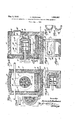
- Figure 1 is a transverse section showing one construction by which a cylinder or crucible may be pro-formed by smtering.
- Figure 2 is a section of Figure l on line showing a different means of making the mould resilient.
- Figure 7 is a transverse section showing a cylinder which has been fully sintered and which has been grooved to relieve from crack- %igure 8 is a section corresponding to Figure 7 but showing the grooves as filled in.
- Sintering per se, is old and it is also old to sinter linings in furnaces, using magnesite, or other refractory materials such as dolomite, with flux.
- this sintering has to be performed in the diflicult conditions and surroundings of intended use, has laid the final surface which is to be exposed'for use against crackingof the surface due to tem- I perature changes.
- My invention is intended to provide methods by which sintered products can be cheaply and effectively constructed and to. secure a better and different product from the sintered product which is now available.
- the main characteristic of my sintering is that, as distinguished from sintering in place I pre-form a product or shape by sintering it upon or against a mould or pattern from which it is subsequently removed, or wh ch is subsequently broken from it to free the sintered product.
- the top 12, one end 13, base 14 and aid walls 15 are shown as fixed and comprise a casing.
- the base 14 forms a track for anti friction balls or rollers 16 upon which is supported the shell 17 of a movable carrier including a refractory fioor and closing end 18.
- the walls of the furnace are formed of any suitable refractory for which I find dolomite well adapted.
- the pattern or mould is shown in Figure 1 as slitted parallel with the axis at 19 to increase resilience and compressibility.
- the pattern is mounted upon using the refractory bottom of the furnace and exposing the sur-
- the carrier can be ro ed into position with-
- An opening is provided'at 25. covered at 25' for inspection and for insertion of sintering materials.
- Electrodes are shown in position to heat the sides and ends respectively of the product being sintered.
- the pattern and mould may be made of any suitable neutral material of which dolomite is a cheap example but for which graphite is more lasting. I mix it with'tar or some similar ingredient which holds the dolomite together and will burn out during sintering or during the pre-heating before so that the mould may be destroyed easily after the sintering of the product has been completed.
- the furnace is preferably heated preliminari- 1y: by flame from an pil or gas burner 26, while the cylinder is turned from time to time, in order to burn out the tar before the sintering begins and to permit a more gradual heating up of the pattern than would take place if the higher temperature of the arc were applied locally at one side or end.
- the cylinder After the cylinder hasbeen heated up by the oil or gas burner it may be further heated by the electric arcs.
- a thin parting layer may be used initially.
- Various materials are suitable for this purpose such as pure powdered refractory (i. e. lacking a flux) or graphite. Where graphite is used for the mould its material serves this purpose also.
- the percentage of slag or flux need not be great. Satisfactory percentages of different fluxes are well known. It is desirable to reduce the slag content as the sintering operation proceeds.
- FIGS. 4 and 5 I show a mould 27 made of a neutral material such as dolomite-tar containing an opening 28 adapted to mould a brick or block or hearth or other shape, for use in building up a refractory lining.
- This is intended to represent a fixed sintered product pre-formed in a mould and adapted to form either the whole or a part of a refractory bed or lining.
- the brick, block, hearth, etc. may be formed within a furnace of the same character as that shown in Figure 1 by laying and sintering successive-,
- the product may be shaped for use.
- the size of the brick shown is small enough so that it would not be necessary to shift it beneath the arcs for sintering successive la ers and the entire area of the brick ma g sintered at one time. It will not,,there ore, be necessar mouldlongltudinally nor laterally but such movements would be required and can easily be provided for when the product is a large one.
- my invention makes up sintered crucibles, cylinders, blocks, etc. free from the difiiculties of surroundings and location present where the sintering is done in place, that the surface of the sintered material which is intended to be used may be Very exactly predetermined by the contour and finish of the mould, without the necessity for care in this particular in the manufacture, that the surface intended to be used may be given a finish better than that which is left at the back of a sintered wall where the work is done in place, and that the mould may be moved as need occurs to easily and conveniently render the whole surface accessibleto the greatest extent for the sintering operation.
- Such language as has been used as is based upon the mould being inside of the sintered refractory is to be given a meaning to cover a reversal of these positions as the invention ternatively to provide other protection against crackin of the backing of the refractory at the face of the backing.
- the protection against cracking by grooving is based upon-the idea that the outer surface shall be relieved from circumferential strain due to temperature changes; that the methods by variation of the composition andby difi'erence in extent of sintering are based upon the ideas of tou hening the outer layer and altering its sur ace characteristics to stand the strain and to reduce the frangibility, rather than by increasing the strength to withstand the strain.
- the method of forming and sintering a refractory for holding molten metals which consists in forming and sintering firstthe surface of the refractory which is to receive the molten metal and subsequently and successively forming and sintering the backing of the refractory.
- the method of forming and sintering material to form a refractory for use to hold molten metals which consists in forming the surface portion ofthe refractory which is to receive the molten metal against a pattern or mould, sintering it against the pattern or mould and successively and progressively increasing t he thickness of the sintered product by forming successive layers outside of the previously sintered product and sintering these layers into homogeneous engagement with the product already sintered to form a backing for the surface.
- the method of forming and sintering objects upon a mould and removing the mould which consists in providing a mould having parts adapted to be weakened by the application of heat, in supplying heat to weakenthe mould, in sintering a refractory about the mould and in destroying'the heatweakened mould. 4
- the method of sintering which comprises forming a mould having an ingredient adapted to burn out, in heating the mould to burn out this ingredient and in sintering a. 19 product upon the mould after the ingredient adapted to be burned out has been removed.
Landscapes
- Engineering & Computer Science (AREA)
- Mechanical Engineering (AREA)
- Manufacturing & Machinery (AREA)
- Compositions Of Oxide Ceramics (AREA)
Description
M y 3, 1932- H. NEUHAUSS 1,856,851 S INTERING REFRACTORIES FROM MOLTEN MAGNESITE OR OTHER MATERIALS Filed Aug. l,Al928 Patented May 3, 1932 I UNITED STATES PATENT OFFICE HEINRICH NEUHAUBS, F DUBSELDOBF, GERMANY, ASSIGNOR TO TEE AJAX METAL COMPANY, OF PHILADELPHIA, PENNSYLVANIA,
VANIA A CORPORATION OI PENNSYL- Application filed August 1, 1928. Serial No. 296,803.
. Mg invention relates to methods of sinter in u rnace linings and other like surfaces. ne purpose of my invention 1s to form the sintered surface which is to be actively engaged by a furnace charge, 'for'example, against a mould or pattern which is afterward to be removed or destroyed, permitting accurate predetermination of the finished shape and surface of the sintered product.
A further purpose is to lay that surface first which is to be actively engaged by the furnace charge, making it possible to obtain more perfect sintering and greater uniformity and smoothness and continuity of the 3 active surface than would otherwisebe the A further purpose is to pre-form sintered tions of position, space and equipment and to obtain better sintered products.
A further purpose is to rform the sintering operation in a specia y prepared sintering furnace free from the limitations and difficulties of location of the place of use.
A further purpose is to protect a sintered product from cracking by reason of temperature changes by relief of the backing supporting the surface of use.
A further purpose is to provide a form about or within which products are sintered and which is firm enough to stand the pressure of the sintered product and maintain its shape and yet is yieldable enough to avoid injury to the product, inters rsing material for this purpose which can baked out or burned out.
A further purpose is to form a special backing for a sintered refractory.
Further purposes will appear in the specification and in the claims.
My drawings are intended to be largely diagrammatic, and for this reason have been distorted freely for the purpose of illustration and without any attempt to maintain a scale. They are intended to illustrate a few only of the forms and ways upon which or in or by which my invention. may be carried out, those shown being selected primarily from the standpoint of illustration of the invention.
Figure 1 is a transverse section showing one construction by which a cylinder or crucible may be pro-formed by smtering.
' Figure 2 is a section of Figure l on line showing a different means of making the mould resilient.
Figure 7 is a transverse section showing a cylinder which has been fully sintered and which has been grooved to relieve from crack- %igure 8 is a section corresponding to Figure 7 but showing the grooves as filled in.
In the drawings similar numerals indicate like parts.
Sintering, per se, is old and it is also old to sinter linings in furnaces, using magnesite, or other refractory materials such as dolomite, with flux. However, this sintering has to be performed in the diflicult conditions and surroundings of intended use, has laid the final surface which is to be exposed'for use against crackingof the surface due to tem- I perature changes.
With increasing size and thickness of furnace walls, it becomes more and more important to supply sintered bricks or blocks layer between the sintered refractory and the mould.
My invention is intended to provide methods by which sintered products can be cheaply and effectively constructed and to. secure a better and different product from the sintered product which is now available.
The main characteristic of my sintering is that, as distinguished from sintering in place I pre-form a product or shape by sintering it upon or against a mould or pattern from which it is subsequently removed, or wh ch is subsequently broken from it to free the sintered product.
No attempt has been made to show a complete list of such products or the ways in which my invention may be practiced. I have shown means for moving the product and mould during the sintering operation and an operation intended to be effective upon a stationary product, to ind cate that neither the movement nor the stationary character of the parts during operation is essential to the broader features of my invention, and have shown a complete crucible and partly complete crucible (a cylinder only, lacking a bottom) and a brick for the purpose of indicating that the completeness or lack of completeness of the product as compared with the final container also are not material in the broader aspects of my invention.
In Figures 1 to 3 I have shown my invention as applied to the making of a crucible 10, using a rotatable form or pattern 11 upon which to sinter the crucible. I prefer to make the form or pattern out of a type of' material which will stand the temperature without undue surface shrinkage and which will be sufliciently yielding and eas ly destroyed to avoid injury to the product during the sintering or in removal of the pattern.
Because it is desirable to perform the sintering within a furnace where the heat can be applied to the best advantage I have shown one for illustration which is convenient but not essential. In it provision has also been made for ready introduction of the pattern into the furnace. I
The top 12, one end 13, base 14 and aid walls 15 are shown as fixed and comprise a casing. The base 14 forms a track for anti friction balls or rollers 16 upon which is supported the shell 17 of a movable carrier including a refractory fioor and closing end 18.
The walls of the furnace are formed of any suitable refractory for which I find dolomite well adapted.
The pattern or mould is shown in Figure 1 as slitted parallel with the axis at 19 to increase resilience and compressibility.
Because it is the intention to move the form 11 dur ng sintering and the movement required by the character of product illustrated is rotarial, the pattern is mounted upon using the refractory bottom of the furnace and exposing the sur- The carrier can be ro ed into position with-,
in the casing to comtpletely close the casing,
oor of the shell 17 as the face of themould to the inten e heat from electric arcs fed through elect cs 23 or 24.
An opening is provided'at 25. covered at 25' for inspection and for insertion of sintering materials.
Electrodes are shown in position to heat the sides and ends respectively of the product being sintered.
. The pattern and mould may be made of any suitable neutral material of which dolomite is a cheap example but for which graphite is more lasting. I mix it with'tar or some similar ingredient which holds the dolomite together and will burn out during sintering or during the pre-heating before so that the mould may be destroyed easily after the sintering of the product has been completed.
When the tar-dolomite pattern is in place the furnace is preferably heated preliminari- 1y: by flame from an pil or gas burner 26, while the cylinder is turned from time to time, in order to burn out the tar before the sintering begins and to permit a more gradual heating up of the pattern than would take place if the higher temperature of the arc were applied locally at one side or end.
After the cylinder hasbeen heated up by the oil or gas burner it may be further heated by the electric arcs.
When the pattern is warm enough its movement will be stopped in order that one part of it may be madequite hot. A sintering material such as magnesite or other refractory v powder, with a little slag, iron oxide or other flux will then be spread on the hot place and the heating will be continued until the test shows that the magnesite has been sintered. New parts are heated progressively and new, thin layers of the powdered refractory and flux are added about the circumference until a complete cylinder has been formed. The
' application of powdered refractory and flux and heating is progressively continued in layers about the cylinder. Each successive part and layer is fused into homogeneous engage-' ment with its adjacent parts and layers at the sides and beneath it so that when the cylinder is completed it will comprise a homogeneous mass of thoroughly joined fused refractory.
Where it is desired to facilitate parting from the pattern a thin parting layer may be used initially. Various materials are suitable for this purpose such as pure powdered refractory (i. e. lacking a flux) or graphite. Where graphite is used for the mould its material serves this purpose also.
If a cylinder only be desired the product Will now be complete, but if it be desired to cross-section inside and outside, my method is suited to sinter refractories of all shapes. This apparatus or other apparatus prov1d1ng movement is suited to sinter fully products of different cross-section, provided:
(a) That the products do not differ too far from true cylinders or other shapes to whlch the movement has been suited for the heat of the arcs to properly sinter both the nearer and farther parts of the surface durmg movement of the pattern, or Y 1 (b) That the arcs, or pattern, be laterally moved one toward or away from the other at the different portions of the pattern'so as to maintain the arcs at a suitable sintering distance at all times from the portion of the surface to which the sintered layeris being applied.
The percentage of slag or flux need not be great. Satisfactory percentages of different fluxes are well known. It is desirable to reduce the slag content as the sintering operation proceeds.
While I have illustrated rotary movement only for the pattern it is evident that my .sintering method may be applied to form a sintered product upon a pattern movable according to any other law than that of rotation, the pattern-beifigmoved progressively to bring the successive portions of the pattern which upon layers of magnesite and flux nave been placed within proper sintering distance of the arcs.
After the operation has been completed th pattern and carrier are removed from the furnace and the pattern or mould is broken out of the crucible leaving the crucible complete and finished with its inner surface composed of the layer of sintered material whlch was first laid. Because of this fact this inner layer may be more accurately shaped and better finished than the last laid layers, which would receive the charge if, as previously, the sintering were done in place. My method also makes it possible to pre-form the sintered products at the shop or factory under the most advantageous conditions.
In the form shown in Figures 4 and 5 I show a mould 27 made of a neutral material such as dolomite-tar containing an opening 28 adapted to mould a brick or block or hearth or other shape, for use in building up a refractory lining. This is intended to represent a fixed sintered product pre-formed in a mould and adapted to form either the whole or a part of a refractory bed or lining. The brick, block, hearth, etc., may be formed within a furnace of the same character as that shown in Figure 1 by laying and sintering succes-,
sively layers of powdered refractory mixed with flux until the roduct has been com- 'pleted,- after which 1t is removed from the mould, or the mould is removed from it, so
that the product may be shaped for use.
The size of the brick shown is small enough so that it would not be necessary to shift it beneath the arcs for sintering successive la ers and the entire area of the brick ma g sintered at one time. It will not,,there ore, be necessar mouldlongltudinally nor laterally but such movements would be required and can easily be provided for when the product is a large one.
'Where the furnace refractories sintered .are fairly, large there is a tendency of the refractory product to crack in the outer surfaced the refractory i. e. that farthest removed from the molten metal. I have found that this can be relieved greatly by grinding grooves in the refractory at intervals, as shown at 29. The surface tension is relieved by the grinding of these grooves and the grooves do not have to go far under the surface to relieve against cracking where there is some tendency to break. I prefer not to leave the grooves open but to fill them in with for the operator to shift the powdered magnesite which need not be sintered into position.
In the form shown in Figures 4 and 5 it is desirable also to heat up the mould withoil or gas burners, before the arcs are applied burning out a large part of the tar (where this is used) before are heating for sintering upon or within the mould is begun.
It will be seen that my invention makes up sintered crucibles, cylinders, blocks, etc. free from the difiiculties of surroundings and location present where the sintering is done in place, that the surface of the sintered material which is intended to be used may be Very exactly predetermined by the contour and finish of the mould, without the necessity for care in this particular in the manufacture, that the surface intended to be used may be given a finish better than that which is left at the back of a sintered wall where the work is done in place, and that the mould may be moved as need occurs to easily and conveniently render the whole surface accessibleto the greatest extent for the sintering operation.
Such language as has been used as is based upon the mould being inside of the sintered refractory is to be given a meaning to cover a reversal of these positions as the invention ternatively to provide other protection against crackin of the backing of the refractory at the face of the backing.
It is possible to an unusual degree to vary the hardness of the sintered product by use of a different flux or by varying the percentage of fiux used or by the use of mixed powdered refractories or a different powdered refractory for the final (backing) portion of the sintered refractory which are tougher than those used for the face of the sintered product, or to sinter the outer layers lesscompletely than the inner portion, so as to leave a tougher and less frangible outer layer to protect the outer part of the surface against cracking.
As will be seen the protection against cracking by grooving is based upon-the idea that the outer surface shall be relieved from circumferential strain due to temperature changes; that the methods by variation of the composition andby difi'erence in extent of sintering are based upon the ideas of tou hening the outer layer and altering its sur ace characteristics to stand the strain and to reduce the frangibility, rather than by increasing the strength to withstand the strain.
In View of my invention and disclosure variations and modifications to meet individual whim or particular need will doubtless become evident to others skilled in the art, to obtain all or part of the benefits of my invention without copying the structure shown, and I, therefore, claim all such in so far as they fall within the reasonable spirit and scope of my invention.
Having thus described my invention what I claim as new and desire to secure by Letters Patent is:
1. The method of forming and sintering a refractory for holding molten metals, which consists in forming and sintering firstthe surface of the refractory which is to receive the molten metal and subsequently and successively forming and sintering the backing of the refractory.
2. The method of forming and sintering material to form a refractory for use to hold molten metals, which consists in forming the surface portion ofthe refractory which is to receive the molten metal against a pattern or mould, sintering it against the pattern or mould and successively and progressively increasing t he thickness of the sintered product by forming successive layers outside of the previously sintered product and sintering these layers into homogeneous engagement with the product already sintered to form a backing for the surface.
3. The method of forming and sintering refractories intended to hold molten metal,
' which consists in forming and sintering the refractory against a portion of a pattern or mould, and in moving the pattern or mould .refractory from crac relatively with respect to the source of sintering heat as the layer of refractory is progressively extended to cover a larger part of the mould.
4. The method'of forming and sintering objects upon a mould which consists in forming the mould in part of elements adapted and in destroying the mould already weakened by destruction of these elements to render the sintered product available.
5. The method of forming and sintering objects upon a mould and removing the mould which consists in providing a mould having parts adapted to be weakened by the application of heat, in supplying heat to weakenthe mould, in sintering a refractory about the mould and in destroying'the heatweakened mould. 4
6. The method of protecting a sintered ing of the backing which consists in sintering against the mould a refractory wall adapted to hold the molten metal, in sintering successive layers of the refractory upon that layer against the mould and in finally forming a layer of less completely sintered refractory about the prodnot to form the outside of the backing of the refractory.
7. The method of protecting a refractory against injury by cracking of its backing, which consists in sintering against a pattern or mould a layer which is adapted to hold the metal and in sintering successive layers of refractory about this layer to form a backing for it, forming the final backing of a refractory which is tougher to withstand temperature changes than the refractory face.
8. The method of forming sintered refracv tories for holding molten metal, which consists informing the sintered product, at a distance from the place of intended use,
molten metal from cracking in the backing surface farthest from the molten metal, which consists in grooving the backing of the refractory at intervals to relieve the stress in the backing.
10. The method of protecting a sintered powdered refractory intended to support molten metal, which consists in grooving the backing of the refractory at intervals to relieve the stress in the backing and in filling the grooves formed with powdered magnesite. 7
11. The method of sintering, which comprises forming a mould having an ingredient adapted to burn out, in heating the mould to burn out this ingredient and in sintering a. 19 product upon the mould after the ingredient adapted to be burned out has been removed.
HEINRICH NEUHAUSS.
Publications (1)
| Publication Number | Publication Date |
|---|---|
| US1856851A true US1856851A (en) | 1932-05-03 |
Family
ID=3423726
Family Applications (1)
| Application Number | Title | Priority Date | Filing Date |
|---|---|---|---|
| US1856851D Expired - Lifetime US1856851A (en) | Sintering refbactories fkom molten magnesite ob otheb materials |
Country Status (1)
| Country | Link |
|---|---|
| US (1) | US1856851A (en) |
Cited By (2)
| Publication number | Priority date | Publication date | Assignee | Title |
|---|---|---|---|---|
| US2475810A (en) * | 1944-01-05 | 1949-07-12 | Bell Telephone Labor Inc | Preparation of silicon material |
| US3227416A (en) * | 1960-02-01 | 1966-01-04 | Fessel Paul | Cutting tool |
-
0
- US US1856851D patent/US1856851A/en not_active Expired - Lifetime
Cited By (2)
| Publication number | Priority date | Publication date | Assignee | Title |
|---|---|---|---|---|
| US2475810A (en) * | 1944-01-05 | 1949-07-12 | Bell Telephone Labor Inc | Preparation of silicon material |
| US3227416A (en) * | 1960-02-01 | 1966-01-04 | Fessel Paul | Cutting tool |
Similar Documents
| Publication | Publication Date | Title |
|---|---|---|
| US1812172A (en) | Production of castings free from pipes and blow-holes | |
| TW493004B (en) | Method of manufacturing molten metal iron | |
| US3492383A (en) | Process of manufacturing a crack resistant multi-layer furnace lining | |
| US1856851A (en) | Sintering refbactories fkom molten magnesite ob otheb materials | |
| US1917849A (en) | Refractory lining | |
| US2358652A (en) | Method of making bottoms of high temperature basic furnaces | |
| US9568246B2 (en) | Ramming mass for the refractory lining of a metallurgical vessel, method for the placement thereof and metallurgical vessel, in particular blast furnace, comprising a lining using said ramming mass | |
| US1876733A (en) | Sintering mechanism | |
| US2526289A (en) | Refractory lined container | |
| US2504185A (en) | Method for making basic furnace bottoms | |
| US2294169A (en) | Casting iron and steel | |
| US1922034A (en) | Protective device for electric induction furnaces | |
| CN105424444A (en) | Refractory material slag-resistant sample and preparation method thereof | |
| US3179395A (en) | Slab heating furnaces | |
| US1704902A (en) | Furnace construction | |
| US1954552A (en) | Basic refractory amd method of | |
| US2564009A (en) | Method of repairing reheating furnace bottoms | |
| US1869237A (en) | Method of producing a lining for a rotary furnace | |
| US2220797A (en) | Annealing furnace | |
| US2424825A (en) | Method of repairing open hearth furnace banks | |
| US2631836A (en) | Refractory lining | |
| US1825011A (en) | Metallurgical furnace | |
| US2368270A (en) | Lining rotary furnaces | |
| US3328183A (en) | Refractories | |
| US1876734A (en) | Method of making and patching furnace walls and linings |