US1856838A - Tractor wheel - Google Patents
Tractor wheel Download PDFInfo
- Publication number
- US1856838A US1856838A US464369A US46436930A US1856838A US 1856838 A US1856838 A US 1856838A US 464369 A US464369 A US 464369A US 46436930 A US46436930 A US 46436930A US 1856838 A US1856838 A US 1856838A
- Authority
- US
- United States
- Prior art keywords
- wheel
- cleats
- rim
- radially
- respect
- Prior art date
- Legal status (The legal status is an assumption and is not a legal conclusion. Google has not performed a legal analysis and makes no representation as to the accuracy of the status listed.)
- Expired - Lifetime
Links
- 238000004140 cleaning Methods 0.000 description 3
- 238000010276 construction Methods 0.000 description 1
- 230000000717 retained effect Effects 0.000 description 1
- 230000003313 weakening effect Effects 0.000 description 1
Images

Classifications
-
- B—PERFORMING OPERATIONS; TRANSPORTING
- B60—VEHICLES IN GENERAL
- B60B—VEHICLE WHEELS; CASTORS; AXLES FOR WHEELS OR CASTORS; INCREASING WHEEL ADHESION
- B60B15/00—Wheels or wheel attachments designed for increasing traction
- B60B15/02—Wheels with spade lugs
- B60B15/10—Wheels with spade lugs with radially-adjustable spade lugs; Control mechanisms therefor
Definitions
- This invention relates broadly to wheels, and the primary object of this invention is to provide an improved wheel for tractors.
- the primary object of this invention is to provide a tractor wheel having ground engaging cleats thereon, together with means for adjusting the cleats radially with respect to the wheel whereby to make it possible for the owner of the tractor to have the regular service of a four inch spade cleat and at the same time the convenience of a one-inch cleat, or a two and one half inch cleat, according to the point of adjustment at which the cleats are disposed radially with respect to the wheel.
- a still further object of the invention is to provide a tractor wheel having adjustable cleats associated therewith together with means for expeditiously and conveniently adjusting the cleats radially with respect to the wheel.
- a still further object of the invention is to provide a wheel of this character which is comparatively-simple in construction, wherein the adjustment means for the cleats may be easily operated, and further to provide a wheel of this character which will also permit of facility in the cleaning of the wheel.
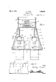
- Figure 1 is a side elevational view of a wheel, certain parts being shown broken away for more fully illustrating the invention
- FIG. 2 is a detail sectional view taken through the wheel on the line 2-2 of Figure 1,
- Figure 3 is a fragmentary top plan view of a portion of the rim of the'wheel.
- the improved tractor wheel comprises essentially a hub 5 having spokes 6 radiating therefrom and at their outer ends secured to a rim 7.
- the rim 7 is preferably channel shaped in cross section.
- the rim 7 is provided on its periphery with a plurality of series of eircumferentially spaced slots, the slots of one series beingar- 1930. Serial No. 464,369.
- a cleat 9 Slidably mounted in each of the slots, for radial movement with respect to the wheel is a cleat 9 of substantially elongated rectangular configuration.
- a lug 10 suitably bolted to the rim asat 11.
- Each of the lugs 10 is provided with a non-circular opening 12 extending therethrough and arranged in alinement with a slot 8 for slidably accommodating the inner end of the cleat 9.
- the lug 10 On opposite sides of the opening 12 the lug 10 is provided with bolt accommodating openings 13 for receiving therein a suitable adjusting bolt 14.
- the cleat 9 is also provided with a plurality of longitudinally spaced bolt accommodating holes 14? adapted to selectively register with the bolt holes 13 for accommodating the bolt 14.- whereby the cleat 9 may be retained at a predetermined point of adjustment radially with respect to the wheel.
- the cleats of the wheel may be adjusted radially with respect to the wheel so that the ground engaging end of the cleats may eX- tend beyond the wheel rim any predetermined 7 portion of its ength, that is of the length of the cleat.
- the cleats may be projected beyond the periphery of the wheel for an inch, two and one-half inches, or. for any other predetermined portion of the length of the cleats.
- a wheel equipped with radially adjustable cleats in the manner comprehended by this invention will have the convenience of a one inch cleat, a'two and one-half inch cleat, etc.
- any mud, snow, or the like that has accumulated on the cleats will be readily removed therefrom thus cleaning the cleats.
- the cleats may be drawn inwardly to such an extent that the outer ends of the cleats may be substantially flush with the outer face. of the wheel rim 7 so that the periphery of the wheel will be Suchmoans comprises an annular member arranged 'CODCGDtllOEIllY of therim 7 and j supported from the rim through the medium of radial metallic supporting straps 16.
- These straps 16 are bolted at one end as at 17 to the side flanges of the rim, and said members are substantially U-shaped to suspend member-15 from the rim 7.
- the member 15 is somewhat channel shaped in cross section, having outwardly extending annular parallel flanges 19.
- the flanges 19 at:their outer edges are cut in somewhat of-a staggered manner to provide radial supporting webs 20 having inclined outeredges 21.
- a shoe 22 For-eachicleat 9 thereis provided what may be termed a shoe 22.
- the shoe 22 comprises a bodyportion provided with a longitudinally extending channel or groove23 that receives therein the outer end portion-of a web-20 so that the shoe rests on the inclined edge of the web 20 and assumes a position corresponding to the edge 21.
- the shoe is secured to the web 20 through the medium of suitable bolts or other fastening elements 24.
- Each shoe 22 is provided on opposite sides thereof with longitudinally extending flanges 25 whose other longitudinaledges are cut somewhat in a zig-zag manner to provide shoulders 26.
- Each of the cleats 9'at the inner end thereof is bifurcated to provide a pairof spaced parallel legs 27 to straddle a shoe 22.
- the legs 27 of the respective cleats at their inner free ends are provided with inwardly'directed extensions 28 to engage the under faces of the flanges 25 of the shoe.
- the shoulders 26 of the respective shoes are arranged in pairs,
- the cleats will be forced either inwardly or outwardly radially with respect to the wheel and according to the direction of rotation of the member 15.
- Rotatably supported between the plates 29 is ashaft 31 that has a relatively large ratchet wheel 82 splined thereto in any suitable manner.
- The. ratchetwheel 32 is in mesh with a relatively smaller ratchet wheel 33 mounted on a .shaft 34; which extends between the plates.
- the ratchet wheel 33 is in mesh" with an arcuate rack bar .35. suitably secured to the member 15 onthe inner faceof themember 15;.
- Any-suitable handle means-(not shown) may beiutilized for rotating the shaft ⁇ 31 for rotating-ratchet wheel 32 for transmitting rotative movement to the member 15in a desired direction-through the medium of the ratchet wheel 33. engaging the teeth .ofthe ratchet bar 35 asiisjapparent.
- the cleats mounted for radialadjustment on the wheel in a -manner comprehendedby the present invention will also permit of easy cleaning of the wheel by simply moving the-cleats radially with-respect to the wheel inwardly and outwardly with respect to the wheel for removing the :mudclots on the cleats.
- a traction wheel comprising in combination a rim provided with a plurality of openings, traction cleats movable radially with respect to the axis of the wheel through said openings, and an annular actuator operable circumferentially within the confines of said rim, cam shoes, there being one cam shoe for each of said cleats, means for detachably connecting said cam shoes with said actuator, said shoes and said cleats having co-operating means for effecting a positive cam connection therebetween whereby to adjust said cleats radially with respect to said rim upon rotation of said actuator, each of said shoes intermediate its ends provided with shoulders en- 5 gageable with a cleat for limiting rotation of said actuator member in one direction when the cleats are fixed at the desired adjustment, and means operable independently of said actuator for fixing the cleats at the desired 0 adjustment relative to the rim.
Landscapes
- Engineering & Computer Science (AREA)
- Mechanical Engineering (AREA)
- Footwear And Its Accessory, Manufacturing Method And Apparatuses (AREA)
Description
May 3, 1932. H, LU AS 1 1,856,838
TRAC TOR WHEEL Filed June' 27, 1930 2 Sheets-Sheet 1 Invenlor May 3, 1932. H, LUCAS 1,858,838
TRACTOR WHEEL Filed June 27, 1930 2 Sheets-Sheet 2 //a r/Lej Zacas Z Fl I nvenlor I Altorney Patented May 3, 1932 UNITED STATES PATNT since HARLEY LUCAS, OF ELMWOOD, ILLINOIS, ASSIGNOB F ONE-HALF TO CORNELIUS A. VANCE, OF ELMWOOD, ILLINOIS TRACTOR WHEEL Application filed June 27,
This invention relates broadly to wheels, and the primary object of this invention is to provide an improved wheel for tractors.
The primary object of this invention is to provide a tractor wheel having ground engaging cleats thereon, together with means for adjusting the cleats radially with respect to the wheel whereby to make it possible for the owner of the tractor to have the regular service of a four inch spade cleat and at the same time the convenience of a one-inch cleat, or a two and one half inch cleat, according to the point of adjustment at which the cleats are disposed radially with respect to the wheel.
A still further object of the invention is to provide a tractor wheel having adjustable cleats associated therewith together with means for expeditiously and conveniently adjusting the cleats radially with respect to the wheel.
A still further object of the invention is to provide a wheel of this character which is comparatively-simple in construction, wherein the adjustment means for the cleats may be easily operated, and further to provide a wheel of this character which will also permit of facility in the cleaning of the wheel.
Other objects and advantages of the invention will become apparent during a study of the following description, taken in connection with the accompanying drawings, wherein:
Figure 1 is a side elevational view of a wheel, certain parts being shown broken away for more fully illustrating the invention,
Figure 2 is a detail sectional view taken through the wheel on the line 2-2 of Figure 1,
Figure 3 is a fragmentary top plan view of a portion of the rim of the'wheel.
Referring in detail to the drawings, it will be seen that the improved tractor wheel comprises essentially a hub 5 having spokes 6 radiating therefrom and at their outer ends secured to a rim 7. The rim 7 is preferably channel shaped in cross section.
V The rim 7 is provided on its periphery with a plurality of series of eircumferentially spaced slots, the slots of one series beingar- 1930. Serial No. 464,369.
ranged in staggered relation with respect to the slots of the other series. Slidably mounted in each of the slots, for radial movement with respect to the wheel is a cleat 9 of substantially elongated rectangular configuration. Secured to the inner face of the rim 7 adjacent each of the slots 8 is a lug 10 suitably bolted to the rim asat 11. Each of the lugs 10 is provided with a non-circular opening 12 extending therethrough and arranged in alinement with a slot 8 for slidably accommodating the inner end of the cleat 9.
On opposite sides of the opening 12 the lug 10 is provided with bolt accommodating openings 13 for receiving therein a suitable adjusting bolt 14. The cleat 9 is also provided with a plurality of longitudinally spaced bolt accommodating holes 14? adapted to selectively register with the bolt holes 13 for accommodating the bolt 14.- whereby the cleat 9 may be retained at a predetermined point of adjustment radially with respect to the wheel.
From the foregoing then it will be seen that the cleats of the wheel may be adjusted radially with respect to the wheel so that the ground engaging end of the cleats may eX- tend beyond the wheel rim any predetermined 7 portion of its ength, that is of the length of the cleat. V
For example the cleats may be projected beyond the periphery of the wheel for an inch, two and one-half inches, or. for any other predetermined portion of the length of the cleats. In this manner, it will be readily appreciated that a wheel equipped with radially adjustable cleats in the manner comprehended by this invention will have the convenience of a one inch cleat, a'two and one-half inch cleat, etc.
Further, it will be seen that by drawing the cleats through the slots 8 and openings 12 of the lugs 10 any mud, snow, or the like that has accumulated on the cleats will be readily removed therefrom thus cleaning the cleats. It will also be apparent that the cleats may be drawn inwardly to such an extent that the outer ends of the cleats may be substantially flush with the outer face. of the wheel rim 7 so that the periphery of the wheel will be Suchmoans comprises an annular member arranged 'CODCGDtllOEIllY of therim 7 and j supported from the rim through the medium of radial metallic supporting straps 16. vVhen thecleats have been projected or retracted radially through the instrumentality of the member 15, the cleats are subsequently secured at the desired adjustment through the medium of the bolts lat passed through the openings '13 in the lugs 10 alining with the holes 1a. in the cleats9 as hereinbefore described.-
These straps 16 are bolted at one end as at 17 to the side flanges of the rim, and said members are substantially U-shaped to suspend member-15 from the rim 7.
The member 15 is somewhat channel shaped in cross section, having outwardly extending annular parallel flanges 19. The flanges 19 at:their outer edges are cut in somewhat of-a staggered manner to provide radial supporting webs 20 having inclined outeredges 21.
For-eachicleat 9 thereis provided what may be termed a shoe 22. The shoe 22 comprises a bodyportion provided with a longitudinally extending channel or groove23 that receives therein the outer end portion-of a web-20 so that the shoe rests on the inclined edge of the web 20 and assumes a position corresponding to the edge 21. The shoe is secured to the web 20 through the medium of suitable bolts or other fastening elements 24.
Each shoe 22 is provided on opposite sides thereof with longitudinally extending flanges 25 whose other longitudinaledges are cut somewhat in a zig-zag manner to provide shoulders 26.
Each of the cleats 9'at the inner end thereof is bifurcated to provide a pairof spaced parallel legs 27 to straddle a shoe 22. The legs 27 of the respective cleats at their inner free ends are provided with inwardly'directed extensions 28 to engage the under faces of the flanges 25 of the shoe. The shoulders 26 of the respective shoes are arranged in pairs,
and the extensions or legs 2. engage the tive cleats, the cleats will be forced either inwardly or outwardly radially with respect to the wheel and according to the direction of rotation of the member 15.
Bolted to a pair of the members 16' as at 18 on opposite sides of the wheel are suitably shaped plates 29. These plates 29 at their inner longitudinal edges are braced with respectv to one another through the medium su tebl r ce ars 0 enfinsbetwew the plates at the ends of the plates.
Rotatably supported between the plates 29 is ashaft 31 that has a relatively large ratchet wheel 82 splined thereto in any suitable manner. The. ratchetwheel 32 is in mesh with a relatively smaller ratchet wheel 33 mounted on a .shaft 34; which extends between the plates. The ratchet wheel 33 is in mesh" with an arcuate rack bar .35. suitably secured to the member 15 onthe inner faceof themember 15;.
Any-suitable handle means-(not shown) may beiutilized for rotating the shaft {31 for rotating-ratchet wheel 32 for transmitting rotative movement to the member 15in a desired direction-through the medium of the ratchet wheel 33. engaging the teeth .ofthe ratchet bar 35 asiisjapparent.
Obviously, by -rotating the member lti in this-mannerand retaining the tractor wheel stationary so that the member 15 movesrelative thereto, the shoescarried by the member will pass between the-legsof'the respective cleats thus moving the cleats, radially through the lugs .10- and slots.8-to position the cleats at anypredetermined point of radial adjustment with respect to the wheels.
ln this manner then it avill be seenthat the cleats may be projectediradially beyond the rim of the wheel for any predetermined {P01}- -tion of their length; From the foregoing character will meet the requirements for: all
general purposes without weakening the wheel in any manner oradding anything to the constructionof the wheel that will hinder the usual operation .of the wheel. Furthermore it will be appreciated that the cleats mounted for radialadjustment on the wheel in a -manner comprehendedby the present invention will also permit of easy cleaning of the wheel by simply moving the-cleats radially with-respect to the wheel inwardly and outwardly with respect to the wheel for removing the :mudclots on the cleats.
Even though I have herein shown and described the preferred embodiment of my invention, it is to be understood that the same is susceptible to changes fully comprehended by the spirit of the invention as herein described, and the scope of the appended claim.
Having thus described my invention, what I claim as new is:
A traction wheel comprising in combination a rim provided with a plurality of openings, traction cleats movable radially with respect to the axis of the wheel through said openings, and an annular actuator operable circumferentially within the confines of said rim, cam shoes, there being one cam shoe for each of said cleats, means for detachably connecting said cam shoes with said actuator, said shoes and said cleats having co-operating means for effecting a positive cam connection therebetween whereby to adjust said cleats radially with respect to said rim upon rotation of said actuator, each of said shoes intermediate its ends provided with shoulders en- 5 gageable with a cleat for limiting rotation of said actuator member in one direction when the cleats are fixed at the desired adjustment, and means operable independently of said actuator for fixing the cleats at the desired 0 adjustment relative to the rim.
In testimony whereof I affix my signature.
HARLEY LUCAS.
Priority Applications (1)
| Application Number | Priority Date | Filing Date | Title |
|---|---|---|---|
| US464369A US1856838A (en) | 1930-06-27 | 1930-06-27 | Tractor wheel |
Applications Claiming Priority (1)
| Application Number | Priority Date | Filing Date | Title |
|---|---|---|---|
| US464369A US1856838A (en) | 1930-06-27 | 1930-06-27 | Tractor wheel |
Publications (1)
| Publication Number | Publication Date |
|---|---|
| US1856838A true US1856838A (en) | 1932-05-03 |
Family
ID=23843668
Family Applications (1)
| Application Number | Title | Priority Date | Filing Date |
|---|---|---|---|
| US464369A Expired - Lifetime US1856838A (en) | 1930-06-27 | 1930-06-27 | Tractor wheel |
Country Status (1)
| Country | Link |
|---|---|
| US (1) | US1856838A (en) |
-
1930
- 1930-06-27 US US464369A patent/US1856838A/en not_active Expired - Lifetime
Similar Documents
| Publication | Publication Date | Title |
|---|---|---|
| US1494797A (en) | Tire | |
| US2467482A (en) | Adjustable wheel mount | |
| US1856838A (en) | Tractor wheel | |
| US1839000A (en) | Agricultural machine | |
| US1487416A (en) | Traction element for tractors | |
| US1779994A (en) | Tractor wheel | |
| US1832926A (en) | Renewable grouser | |
| US1932267A (en) | Tractor lug guard | |
| US1624734A (en) | Method of tamping and tamping machine | |
| US2713521A (en) | Endless band tracks for track type tractors | |
| US1602984A (en) | Wheel | |
| US1945261A (en) | Detachable traction rim for automobiles | |
| US1229210A (en) | Traction-wheel. | |
| US1874943A (en) | Wheel construction | |
| US1192348A (en) | Wheel structure. | |
| US1395422A (en) | Traction-wheel | |
| US1575984A (en) | Bull wheel and the like | |
| US1677568A (en) | Traction wheel | |
| US2478371A (en) | Antiskid device for tires | |
| US1753527A (en) | Resilient wheel | |
| US2466918A (en) | Traction device | |
| US1398890A (en) | Truck-wheel shoe | |
| US2037136A (en) | Tractor wheel tread | |
| US1490574A (en) | Wheel | |
| US1548335A (en) | Wheel-rim construction |