US1856824A - Micrometric divider - Google Patents
Micrometric divider Download PDFInfo
- Publication number
- US1856824A US1856824A US359347A US35934729A US1856824A US 1856824 A US1856824 A US 1856824A US 359347 A US359347 A US 359347A US 35934729 A US35934729 A US 35934729A US 1856824 A US1856824 A US 1856824A
- Authority
- US
- United States
- Prior art keywords
- stem
- block
- micrometric
- divider
- threaded
- Prior art date
- Legal status (The legal status is an assumption and is not a legal conclusion. Google has not performed a legal analysis and makes no representation as to the accuracy of the status listed.)
- Expired - Lifetime
Links
Images

Classifications
-
- G—PHYSICS
- G01—MEASURING; TESTING
- G01B—MEASURING LENGTH, THICKNESS OR SIMILAR LINEAR DIMENSIONS; MEASURING ANGLES; MEASURING AREAS; MEASURING IRREGULARITIES OF SURFACES OR CONTOURS
- G01B3/00—Measuring instruments characterised by the use of mechanical techniques
- G01B3/18—Micrometers
Definitions
- This invention relates to new and useful improvements in geometrical instruments, especially to that type of instrument known as dividers, and aims to provide an etlicient, simple and accurate instrument of this nature that is a considerable improvement from a standpoint of accurate measurement, and simplicity of use over the spring type of dividers now generally in universal use.
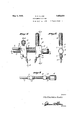
- FIG. 1 is a side elevation of my improved micrometric divider.
- Figure 2 is a rear end elevation thereof.
- Figure 3 is a top plan view.
- Figure a is an enlarged detailed longitudinal section taken substantially upon the line 4- 1 of Figure 1.
- Figure 5 is a fragmentary longitudinal section taken substantially upon the line 5-5 of the same figure.
- Figures 6 and 7 are detailed Vertical sections taken upon the lines 66 and 77 of said Figure 1, and
- Figures 8 and 8a are detailed transverse sections taken upon the lines 88 and 8a-8a, respectively, of Figure 4.
- my novel micrometric dividers consist of a threaded stem 5 of predetermined length having mounted upon one end a thumb turning barrel 6 tapered at its inner end and provided at the tapering surface with predetermined graduations as 1nd1- cated in Figures 1 and 4.
- the stem 5 preferably is threaded to provide approximately forty threads per inch, and said stem 5 1s threaded through a carriage block 7 complementary to which is a stationary block 8, through which the stem 5 projects, thatportion of the stem within the block 8' being unthreaded, as is clearly illustrated in Figure 4.
- the stem 5 is prevented from endwise movement with respect to the stationary block 8 through the medium of a set screw 9 threaded through the lower end of the block, and engaging at its inner end within a channel 10 1232s; seen no! 359,347.
- tlielsi taiffy block 8 is a horizontal measurmg bar 11, havlng securing means consisting 0t a set screw 12.
- Th s measuring bar 11 is graduated preferably in .025 spaces and each fourth line represents .100 and is marked with a number starting from'zero' in predetermined spaced relation with respect to the stationary block 8.
- This thumb screw is:
- knurled head 15 while the upper end of the stationary block 8 is provided with a somewhat elongated knurled handle stem 16, said head and stem providing handles for the dividers.
- the lower ends of the blocks 7 and 8 are formed with oppositely extending diagonal sockets in order to receive the stems of divider points 17 17, said sockets and said points being such that the work engaging surfaces of the points will be exactly parallel as shown in Figure 1. These points may be interchangeable through the medium of set screws 18, threaded within the lower ends of the blocks 7 and 8, respectively.
- An instrument of the character described comprising a threaded stem having an enlarged integral graduated head on one end thereof and an unthreaded portion adjacent the head provided with an annular groove, a block rotatably mounted on the unthreaded portion of the stem having a marker thereon for cooperating with the graduati-ons on the head, a screw threaded into the block for engagement in the groove in a manner to retain said block against longitudinal movement on the stem, a graduated measuring bar rigidly and detachably anchored in the block and extending therefrom in spaced, super posed, parallel relation to the stem, an adjustable block threaded for longitudinal movement on the stem and having an opening through Which the measuring bar slidably extends, said measuring bar constituting means for preventing rotation of the adjustable block with the stem, a set screw, having an enlarged head, threaded into the adjustabletable block for engagement with the measuring bar for releasably securing said adjustable block in adjusted position, divider points detachably secured on the blocks and an upstanding handle member rigidly mounted on
Landscapes
- Physics & Mathematics (AREA)
- General Physics & Mathematics (AREA)
- Length-Measuring Instruments Using Mechanical Means (AREA)
Description
y 3, 1932- R. E. ALVEY 1,856,824
MICROMETRIC DIVIDER Filed April 30, 1929 2 Sheets-Sheet l In 0e 11 for fii ZkERJOA/flLVgY Attorney Fatented 3, 1932 ROY EMERSON ALVEY, or seminars coarseness lvrrononnrnio mvmse Application filed April 30,
This invention relates to new and useful improvements in geometrical instruments, especially to that type of instrument known as dividers, and aims to provide an etlicient, simple and accurate instrument of this nature that is a considerable improvement from a standpoint of accurate measurement, and simplicity of use over the spring type of dividers now generally in universal use.
Other objects will become apparent as the nature of the invention is better understood from a consideration of the following specification in conjunction with the accompanying drawings, and in said drawings Figure 1 is a side elevation of my improved micrometric divider.
Figure 2 is a rear end elevation thereof.
Figure 3 is a top plan view.
Figure a is an enlarged detailed longitudinal section taken substantially upon the line 4- 1 of Figure 1.
Figure 5 is a fragmentary longitudinal section taken substantially upon the line 5-5 of the same figure.
Figures 6 and 7 are detailed Vertical sections taken upon the lines 66 and 77 of said Figure 1, and
Figures 8 and 8a are detailed transverse sections taken upon the lines 88 and 8a-8a, respectively, of Figure 4.
Now having particular reference to the drawings, my novel micrometric dividers consist of a threaded stem 5 of predetermined length having mounted upon one end a thumb turning barrel 6 tapered at its inner end and provided at the tapering surface with predetermined graduations as 1nd1- cated in Figures 1 and 4. The stem 5 preferably is threaded to provide approximately forty threads per inch, and said stem 5 1s threaded through a carriage block 7 complementary to which is a stationary block 8, through which the stem 5 projects, thatportion of the stem within the block 8' being unthreaded, as is clearly illustrated in Figure 4.
The stem 5 is prevented from endwise movement with respect to the stationary block 8 through the medium of a set screw 9 threaded through the lower end of the block, and engaging at its inner end within a channel 10 1232s; seen no! 359,347.
at the adjacent unthreaded portion of said stem, see'Figures sand 7 7 I One side of the stationary block 8 at a point adjacent the graduations of the barrel 6 is provided with a hair line to register with the micrometric position of the graduations on said barrel 6.
. .Secured at one end within the'uppe r end of tlielsi taionary block 8 is a horizontal measurmg bar 11, havlng securing means consisting 0t a set screw 12. Th s measuring bar 11 is graduated preferably in .025 spaces and each fourth line represents .100 and is marked with a number starting from'zero' in predetermined spaced relation with respect to the stationary block 8. I When the dividers are setup one-half degree or .500, a
the measuring bar 11. This thumb screw is:
provided with a large knurled head 15 while the upper end of the stationary block 8 is provided with a somewhat elongated knurled handle stem 16, said head and stem providing handles for the dividers.
The lower ends of the blocks 7 and 8 are formed with oppositely extending diagonal sockets in order to receive the stems of divider points 17 17, said sockets and said points being such that the work engaging surfaces of the points will be exactly parallel as shown in Figure 1. These points may be interchangeable through the medium of set screws 18, threaded within the lower ends of the blocks 7 and 8, respectively.
In view of the foregoing description when considered in conjunction with the accompanying drawings, it will be apparent that I have provided a novel, simple, eflicient and accurate micrometric divider, and even though I have herein shown and described the invention as consisting of certain detailed structural elements, it is nevertheless to be understood that some departures may be had therefrom without afiecting the spirit and scope of the appended claim.
Having thus described my invention, what I claim as new, and desire to secure by Letters-Patent, is:
An instrument of the character described comprising a threaded stem having an enlarged integral graduated head on one end thereof and an unthreaded portion adjacent the head provided with an annular groove, a block rotatably mounted on the unthreaded portion of the stem having a marker thereon for cooperating with the graduati-ons on the head, a screw threaded into the block for engagement in the groove in a manner to retain said block against longitudinal movement on the stem, a graduated measuring bar rigidly and detachably anchored in the block and extending therefrom in spaced, super posed, parallel relation to the stem, an adjustable block threaded for longitudinal movement on the stem and having an opening through Which the measuring bar slidably extends, said measuring bar constituting means for preventing rotation of the adjustable block with the stem, a set screw, having an enlarged head, threaded into the adustable block for engagement with the measuring bar for releasably securing said adjustable block in adjusted position, divider points detachably secured on the blocks and an upstanding handle member rigidly mounted on the first named block.
In testimony whereof I afiix my signature.
ROY EMERSON ALVEY.
Priority Applications (1)
| Application Number | Priority Date | Filing Date | Title |
|---|---|---|---|
| US359347A US1856824A (en) | 1929-04-30 | 1929-04-30 | Micrometric divider |
Applications Claiming Priority (1)
| Application Number | Priority Date | Filing Date | Title |
|---|---|---|---|
| US359347A US1856824A (en) | 1929-04-30 | 1929-04-30 | Micrometric divider |
Publications (1)
| Publication Number | Publication Date |
|---|---|
| US1856824A true US1856824A (en) | 1932-05-03 |
Family
ID=23413435
Family Applications (1)
| Application Number | Title | Priority Date | Filing Date |
|---|---|---|---|
| US359347A Expired - Lifetime US1856824A (en) | 1929-04-30 | 1929-04-30 | Micrometric divider |
Country Status (1)
| Country | Link |
|---|---|
| US (1) | US1856824A (en) |
Cited By (2)
| Publication number | Priority date | Publication date | Assignee | Title |
|---|---|---|---|---|
| US2704892A (en) * | 1953-12-23 | 1955-03-29 | Joseph H Boulet | Micrometric dividers |
| US3123917A (en) * | 1964-03-10 | Interchangeable micrometer frame |
-
1929
- 1929-04-30 US US359347A patent/US1856824A/en not_active Expired - Lifetime
Cited By (2)
| Publication number | Priority date | Publication date | Assignee | Title |
|---|---|---|---|---|
| US3123917A (en) * | 1964-03-10 | Interchangeable micrometer frame | ||
| US2704892A (en) * | 1953-12-23 | 1955-03-29 | Joseph H Boulet | Micrometric dividers |
Similar Documents
| Publication | Publication Date | Title |
|---|---|---|
| US1248340A (en) | Depth-gage. | |
| US2658278A (en) | Multiple precision instrument and tool | |
| US2246066A (en) | Micrometric attachment for combination squares | |
| US2419752A (en) | Beam compass | |
| US1856824A (en) | Micrometric divider | |
| US2614329A (en) | Protractor | |
| US1208662A (en) | Combination-tool. | |
| US2584602A (en) | Inside gauge | |
| US2054503A (en) | Combination tool | |
| US2060927A (en) | Gauge | |
| US1753191A (en) | Combination rule gauge | |
| US2209250A (en) | Scribing trammel for straight and curved lines | |
| US2891317A (en) | Self mastering device for precision setting of tool bits | |
| US1666934A (en) | Instrument for drawing, marking out, and measuring or like purposes | |
| US642750A (en) | Combination measuring-tool. | |
| US2087666A (en) | Measuring device | |
| US2547354A (en) | Center marking caliper | |
| US1357588A (en) | Gage | |
| US1402497A (en) | Calipers | |
| US2489830A (en) | Scribe holding ruler | |
| US439458A (en) | Richard e | |
| US2267332A (en) | Direct reading positive measuring micrometer gauge | |
| US1858116A (en) | Caliper or divider | |
| US2354737A (en) | Combination scale | |
| US1489747A (en) | Micro height gauge |