US1856817A - Blow-out preventer - Google Patents
Blow-out preventer Download PDFInfo
- Publication number
- US1856817A US1856817A US216309A US21630927A US1856817A US 1856817 A US1856817 A US 1856817A US 216309 A US216309 A US 216309A US 21630927 A US21630927 A US 21630927A US 1856817 A US1856817 A US 1856817A
- Authority
- US
- United States
- Prior art keywords
- valve
- housing
- packing
- drill stem
- valves
- Prior art date
- Legal status (The legal status is an assumption and is not a legal conclusion. Google has not performed a legal analysis and makes no representation as to the accuracy of the status listed.)
- Expired - Lifetime
Links
- 238000012856 packing Methods 0.000 description 22
- 239000012530 fluid Substances 0.000 description 10
- 238000005553 drilling Methods 0.000 description 4
- 238000010276 construction Methods 0.000 description 3
- 230000015572 biosynthetic process Effects 0.000 description 2
- 238000005755 formation reaction Methods 0.000 description 2
- 241001251753 Riparia cincta Species 0.000 description 1
- NINIDFKCEFEMDL-UHFFFAOYSA-N Sulfur Chemical compound [S] NINIDFKCEFEMDL-UHFFFAOYSA-N 0.000 description 1
- 239000005864 Sulphur Substances 0.000 description 1
- 238000007664 blowing Methods 0.000 description 1
- 210000004907 gland Anatomy 0.000 description 1
- 239000007788 liquid Substances 0.000 description 1
- 230000003340 mental effect Effects 0.000 description 1
- 210000002445 nipple Anatomy 0.000 description 1
Images

Classifications
-
- E—FIXED CONSTRUCTIONS
- E21—EARTH OR ROCK DRILLING; MINING
- E21B—EARTH OR ROCK DRILLING; OBTAINING OIL, GAS, WATER, SOLUBLE OR MELTABLE MATERIALS OR A SLURRY OF MINERALS FROM WELLS
- E21B33/00—Sealing or packing boreholes or wells
- E21B33/02—Surface sealing or packing
- E21B33/03—Well heads; Setting-up thereof
- E21B33/06—Blow-out preventers, i.e. apparatus closing around a drill pipe, e.g. annular blow-out preventers
- E21B33/061—Ram-type blow-out preventers, e.g. with pivoting rams
- E21B33/062—Ram-type blow-out preventers, e.g. with pivoting rams with sliding rams
Definitions
- Patented lVIay 3 1932 UNITED STATES I JOHN B. MARTIN AND WALTER E. KING, OF HOUSTON, TEXAS, ASSIGNORS, BY DIRECT AND MESNE ASSIGNMENTS, 0F ONE-HALF TO SAID MARTIN, AND ONE-HALF T0 JAMES S. AIBERCROMBIE, OF HOUSTON, TEXAS BLOW-OUT PREVENTER Application filed August 29, 1927. Serial No. 216,309.
- Our invention relates to means for preventing the blowin out of wells for oil, gas, sulphur and the like. It is adapted for attachment to the upper end of the well casing to close the space between the casing and the drill stem in' rotary drilling when there is danger of the gas blowing from the well.
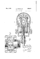
- Fig. 1 is a side view of a blowout preventer embodying our invention, the principal parts of the device being shown in central vertical section.
- Fig. 2 is a transverse section through the housing of the blow- .out preventer shown in Fig. 1 with the valves in open position.
- Fig. 3 is a vertical section approximately on the line 33 of Fi 2.
- Fig. 4 is a' -perspective view of the pac 'ng cups employed with the valves shown in ur device is intended for operation upon the ordinary casing employed in well drillprojecting laterally therefrom and ap mately rectangular in shape. Withm theing, such casing being shown at 1.
- the device comprises a housing 2 threaded "at its lower end for attachment to the well casing, and also having an upper nipple 3 for engagement with the casing 4 above the preventer.
- the casing 2 has centrally thereof a housing 8, said housing being flattened somewhat transversely of the well casing but of greater diameter than said casing to form therein a chamber 7 within which the valves of the preventer may move.
- the chamber 7 is approximately cylindrical at one end, as shown in Fig. 2, but has an extension at one side of the casing rox1- chamber 7 at one side of the drill stem 6 is a valve 9 which has its forward face adjacent the, drill stem provided with a recess 10.
- each of the cups is recessed at 14 to receive a segment 15, semi-circular in shape, which fits within the recess in the cup and reinforces the same so as to hold it ri idly against the seat in which it is placed.
- the upper portion of the cup 13 has a lip, indicated at 17, presented outwardly under which fluid tending to pass the ring from the outside may engage and force the cup more firmly against the upper wall of the chamber 7.
- a lip, shown at 18, which is directed inwardly and so arranged that when the fluid from the lower side of the valve tends to pass upwardly past the packing, these lips 18 and 18 will be forced against the pipe, thus tending to preserve a tight closure.
- valve 19 On the opposite side of the drill stem is the valve 19, said valve being slightly wider than the valve 9 and extended into contact with the side walls of the extension 20 upon the valve chamber.
- the forward side of the valve is recessed at 21, as in the case of the opposite valve, so as to fit against the drill stem.
- cups 13' identical with those upon the opposite side to pack the forward and outer sides of the valve, maintaining a seal between the valve and the casing and between the valve and the drill stem.
- the two valves 9 and 19 are operated to and from the drill stem to close the space about the same by means of a threaded shaft 22.
- Said shaft is threaded s t 23 within the housing to engage within a yoke 24 for operation of the valve 9.
- the forward end of the shaft is reduced in diameter and threaded at 25 for engagement with a boss 26 upon the outer side of the valve 19, and it is to be understood thatthe thread upon the larger portion 23 of the valve is threaded in one direction, while the portion 25 is threaded in the opposite direction so that when the shaft is rotated in one direction the valves will be moved either toward or away from each other, depending upon the direction of rotation of the shaft.
- the yoke 24 is connected with the valve 9 through means of bolts 27, said bolts being threaded into enga ement with the yoke 24 at one end and are sli able within openings 29 in the valve 19 and the outer ends are secured rigidly to the ends of the valve 9 by means of clamping nuts 30.
- the engagement between the portion 25 of the shaft and the valve 19 is shown in both Figs. 1 and 2.
- the boss 26 has an interior chamber 31 and outside this chamber the recess to receive the bolt is threaded and it will be obvious that the rotation of the shaft will move the valve 19 in either direction, depending upon the direction of rotation of the shaft.
- the shaft 22 has a bearing within an extension 32, upon the housing.
- This extension has an inner chamber 33 within which a radial flange 34 on the shaft is fitted and this flange engages with packing rings 35 on either side thereof and is prevented from movement longitudinally of the housing by means of a ring nut 36 on the inner side and an inwardly extending flange 37 on the outer 1 side.
- a stufiing box including a chamber with packing 38 therein and a gland 39 fitting upon said packing and moved into contact therewith by a threaded cap 40.
- the end of the extension chamber 20 is removable. cap plate which is clamped to the rest of the housing by means of clamping bolts 42.
- valves will be normally open so that the drill stem 6 may be operated therethrough in the drilling of the well, and when the valves are in their open position they will be spaced away from the opening through the casing so that there will be no contact of the drill stem there-.
- valves When indications are shown that the gas pressure is tending to blow the liquid from the well, the valves may be closed and this may be accomplished so as to close the valves from each side simultaneously by the rotation of the shaft 22 in such direction as to move the valves toward the drill stem.
- the packing cups 13 and 13 When the valves are tightened into position against the drill stem, the packing cups 13 and 13 will be brought firmly into contact with the drill stem so that there will be no danger of leakage of fluid around the stem. Furthermore, the outer ends of the cups will be pressed firmly against the walls of the housing and because of the arrangement of the cups the fluid under pressure tending to pass the edges of the packing will serve to force the packing more firmly into contact with the wall and thereby tend to prevent leakage.
- a blowout preventer adapted for use in combination with a well casing having a drill stem therein, a housing on said casing, opposite valve members in said casing, segmental packing at the upper and lower sides of said valves adapted to fit about a drill stem, lips on said packing presented in the direction to be expandedby fluid pressure, and means to move said valves toward said drill stem.
- a blowout preventer adapted for use in combination with a well casing having a drill stem therein, a housing on said casing, opposite valve members in said casing,segmental packing at the upper and lower sides -of said valves adapted to fit about a drill ously toward and away from said drill stem.
- aeeaarv in a blowout preventer adapted for use 111 combination with a well caslng having a drill stem therein, a housing, valve members shaped to fit about said drill stem and to close the space within said housing outside said drill stern, and packing cups on said valve members secured thereto and having fluid engaging lips presented in the direction of the fluid pressure to prevent the passage or liuid about said members.
- a. in ablowout preventei adapteo L011 use on a Well casing a housing, opposite valve members in said housing, segmental packing cups at the upper and lovver sides of said valves, lips on said cups presented in the direction to be expanded by liuid pressure acting on said valves, and meansto move said valves toward the center of said housing.
- a housing in a blovrout preventer, a housing, a valve therein, a resilient packing cup carried by said valve, including portions to contact with the drill pipe and portions to contact with said housing, and means connected to said valve to hold said cup thereto,
- a blowout preventer a main body member, a passage therethrough, flat surfaces circumjacent the said passage, valve members radially slidable on said surfaces and with relation to the said passage, resilient cuplike packing elements, means for attaching said packing elements to said valve memhers, said packing elements being adapted to seal against the said flat surfaces and across the faces of the said valve members,
Landscapes
- Life Sciences & Earth Sciences (AREA)
- Engineering & Computer Science (AREA)
- Geology (AREA)
- Mining & Mineral Resources (AREA)
- Physics & Mathematics (AREA)
- Environmental & Geological Engineering (AREA)
- Fluid Mechanics (AREA)
- General Life Sciences & Earth Sciences (AREA)
- Geochemistry & Mineralogy (AREA)
- Valve Housings (AREA)
Description
May 3, 1932 J. R. MARTIN ET AL BLOW-OUT PREVENTER Filed Aug. 29, 1927 2 Sheets-Sheet l IVEN ITQRS /E m AVTTYORNEYS.
y 3, 19327 7 J. R. MARTIN ET AL 1,356,817
BLOW- OUT PREVENTER Filed Aug. 29, 1927 2 SheetS-Qheet 2 IN VEN TORS 3W ATTORNEYS.
Patented lVIay 3, 1932 UNITED STATES I JOHN B. MARTIN AND WALTER E. KING, OF HOUSTON, TEXAS, ASSIGNORS, BY DIRECT AND MESNE ASSIGNMENTS, 0F ONE-HALF TO SAID MARTIN, AND ONE-HALF T0 JAMES S. AIBERCROMBIE, OF HOUSTON, TEXAS BLOW-OUT PREVENTER Application filed August 29, 1927. Serial No. 216,309.
Our invention relates to means for preventing the blowin out of wells for oil, gas, sulphur and the like. It is adapted for attachment to the upper end of the well casing to close the space between the casing and the drill stem in' rotary drilling when there is danger of the gas blowing from the well.
In formations where gas is encountered in drilling deep wells, particularly oil and gas wells, it frequently happens when the producing stratum is encountered that the gas pressure becomes excessive and tends to blow the fluid from the well and this sometimes occurs with such violence as to wreck the drilling apparatus. If the upper end of the well is closed off in such manner as to prevent the gas from starting to blow out of the casing this may be prevented without much danger.
It is therefore an object of our invention to provide an attachment for the well casing which is adapted to close off the space about the drill stem within the casing and prevent the escape of fluid therefrom and to provide means for closing the valves on both sides of the drill stem simultaneously and expeditiously.
It is desired to provide an eflicient type of valve for use with a blowout preventer of the character stated and to provide a particularly accessible and easily operated means for closing the said valves.
The invention resides particularly in the effective and convenient arrangement of the parts making up the invention and reference is made to the drawingsherewith wherein a preferred embodiment of this invention is disclosed.
In the drawings, Fig. 1 is a side view of a blowout preventer embodying our invention, the principal parts of the device being shown in central vertical section. Fig. 2 is a transverse section through the housing of the blow- .out preventer shown in Fig. 1 with the valves in open position. Fig. 3 is a vertical section approximately on the line 33 of Fi 2. Fig. 4 is a' -perspective view of the pac 'ng cups employed with the valves shown in ur device is intended for operation upon the ordinary casing employed in well drillprojecting laterally therefrom and ap mately rectangular in shape. Withm theing, such casing being shown at 1. The device comprises a housing 2 threaded "at its lower end for attachment to the well casing, and also having an upper nipple 3 for engagement with the casing 4 above the preventer.
It is customary to provide above the blowout preventer a gate valve, shown at 5, by means of which the whole interior of the well casing above the drill stem, shown at 6, may be closed. This construction and forms no part of the present invention.
Referring to the blowout preventer, the casing 2 has centrally thereof a housing 8, said housing being flattened somewhat transversely of the well casing but of greater diameter than said casing to form therein a chamber 7 within which the valves of the preventer may move.
The chamber 7 is approximately cylindrical at one end, as shown in Fig. 2, but has an extension at one side of the casing rox1- chamber 7 at one side of the drill stem 6 is a valve 9 which has its forward face adjacent the, drill stem provided with a recess 10.
to fit about the drill stem being used. On the side opposite the recess 10 is a strengthenlng rib 11 serving to reinforce the central portion of the valve. The upper and lower sides of the valve are recessed at 12 to receive a packing cup 13 as best seen in Fig. 1. The construction of these cups per se is shown best in F ig. 4. They are semi-circular in plan vlew, the orward side being shaped to fit the drill stem and the rearward side to fit the recess 12 in the valve. The outer side of each of the cups is recessed at 14 to receive a segment 15, semi-circular in shape, which fits within the recess in the cup and reinforces the same so as to hold it ri idly against the seat in which it is placed. ap screws 16-are employed to secure the segments 15 within their seats, clamping the packing firmly in position. As previously stated, there are segments and packing rings of identical formation both on the upper and lower sides of the valve, thus guarding against the inlet of fluid from either side, and it is to be noted that the upper portion of the cup 13 has a lip, indicated at 17, presented outwardly under which fluid tending to pass the ring from the outside may engage and force the cup more firmly against the upper wall of the chamber 7. Also on the lower side of the cup 13 is a lip, shown at 18, which is directed inwardly and so arranged that when the fluid from the lower side of the valve tends to pass upwardly past the packing, these lips 18 and 18 will be forced against the pipe, thus tending to preserve a tight closure.
On the opposite side of the drill stem is the valve 19, said valve being slightly wider than the valve 9 and extended into contact with the side walls of the extension 20 upon the valve chamber. The forward side of the valve is recessed at 21, as in the case of the opposite valve, so as to fit against the drill stem. There are cups 13' identical with those upon the opposite side to pack the forward and outer sides of the valve, maintaining a seal between the valve and the casing and between the valve and the drill stem.
The two valves 9 and 19 are operated to and from the drill stem to close the space about the same by means of a threaded shaft 22. Said shaft is threaded s t 23 within the housing to engage within a yoke 24 for operation of the valve 9. The forward end of the shaft is reduced in diameter and threaded at 25 for engagement with a boss 26 upon the outer side of the valve 19, and it is to be understood thatthe thread upon the larger portion 23 of the valve is threaded in one direction, while the portion 25 is threaded in the opposite direction so that when the shaft is rotated in one direction the valves will be moved either toward or away from each other, depending upon the direction of rotation of the shaft. The yoke 24 is connected with the valve 9 through means of bolts 27, said bolts being threaded into enga ement with the yoke 24 at one end and are sli able within openings 29 in the valve 19 and the outer ends are secured rigidly to the ends of the valve 9 by means of clamping nuts 30. The engagement between the portion 25 of the shaft and the valve 19 is shown in both Figs. 1 and 2. The boss 26 has an interior chamber 31 and outside this chamber the recess to receive the bolt is threaded and it will be obvious that the rotation of the shaft will move the valve 19 in either direction, depending upon the direction of rotation of the shaft.
The shaft 22 has a bearing within an extension 32, upon the housing. This extension has an inner chamber 33 within which a radial flange 34 on the shaft is fitted and this flange engages with packing rings 35 on either side thereof and is prevented from movement longitudinally of the housing by means of a ring nut 36 on the inner side and an inwardly extending flange 37 on the outer 1 side. Beyond the flange 37 is a stufiing box including a chamber with packing 38 therein and a gland 39 fitting upon said packing and moved into contact therewith by a threaded cap 40. As will be seen from the drawings, the end of the extension chamber 20 is removable. cap plate which is clamped to the rest of the housing by means of clamping bolts 42.
In the operation of this device, the valves will be normally open so that the drill stem 6 may be operated therethrough in the drilling of the well, and when the valves are in their open position they will be spaced away from the opening through the casing so that there will be no contact of the drill stem there-.
with. When indications are shown that the gas pressure is tending to blow the liquid from the well, the valves may be closed and this may be accomplished so as to close the valves from each side simultaneously by the rotation of the shaft 22 in such direction as to move the valves toward the drill stem. When the valves are tightened into position against the drill stem, the packing cups 13 and 13 will be brought firmly into contact with the drill stem so that there will be no danger of leakage of fluid around the stem. Furthermore, the outer ends of the cups will be pressed firmly against the walls of the housing and because of the arrangement of the cups the fluid under pressure tending to pass the edges of the packing will serve to force the packing more firmly into contact with the wall and thereby tend to prevent leakage. It is contemplated that the The end thereof is formed into a threaded portions 23 and 25 will be formed I with a coarse thread so that the operation of the valves will be fairly rapid and itwill be, therefore, noted that the closure can be performed expeditiously by one operator. The advantages of this construction will be apparent without further description.
. What we claim as new is: 1
1. In a blowout preventer adapted for use in combination with a well casing having a drill stem therein, a housing on said casing, opposite valve members in said casing, segmental packing at the upper and lower sides of said valves adapted to fit about a drill stem, lips on said packing presented in the direction to be expandedby fluid pressure, and means to move said valves toward said drill stem.
2. In a blowout preventer adapted for use in combination with a well casing having a drill stem therein, a housing on said casing, opposite valve members in said casing,segmental packing at the upper and lower sides -of said valves adapted to fit about a drill ously toward and away from said drill stem.
aeeaarv in a blowout preventer adapted for use 111 combination with a well caslng having a drill stem therein, a housing, valve members shaped to fit about said drill stem and to close the space within said housing outside said drill stern, and packing cups on said valve members secured thereto and having fluid engaging lips presented in the direction of the fluid pressure to prevent the passage or liuid about said members.
a. in ablowout preventei adapteo L011 use on a Well casing, a housing, opposite valve members in said housing, segmental packing cups at the upper and lovver sides of said valves, lips on said cups presented in the direction to be expanded by liuid pressure acting on said valves, and meansto move said valves toward the center of said housing.
5. in a blovrout preventer, a housing, a valve therein, a resilient packing cup carried by said valve, including portions to contact with the drill pipe and portions to contact with said housing, and means connected to said valve to hold said cup thereto,
ln a valve structure, a housing, a pair of rams movablein said housing, a front face on each of said rams, a face on each of said rams to engage said housing, packing car ried by said rams, and enlarged contact areas on said packing presented on both of said faces, I
7. Flu a blowout preventer, a housing having a passage therethroug'h, cooperating valve members slidable Within said housing, se mental cup-like packing members secured to said valve members and adapted to seal around said passage when the valve members are in a closed position.
8. In a blowout preventer, a main body member, a passage therethrough, flat surfaces circumjacent the said passage, valve members radially slidable on said surfaces and with relation to the said passage, resilient cuplike packing elements, means for attaching said packing elements to said valve memhers, said packing elements being adapted to seal against the said flat surfaces and across the faces of the said valve members,
c In testimony whereof we hereunto al'lin our signatures this 23d day of August, A. D.
JOHN R. MARTIN. WALTER E. KING.
Priority Applications (1)
| Application Number | Priority Date | Filing Date | Title |
|---|---|---|---|
| US216309A US1856817A (en) | 1927-08-29 | 1927-08-29 | Blow-out preventer |
Applications Claiming Priority (1)
| Application Number | Priority Date | Filing Date | Title |
|---|---|---|---|
| US216309A US1856817A (en) | 1927-08-29 | 1927-08-29 | Blow-out preventer |
Publications (1)
| Publication Number | Publication Date |
|---|---|
| US1856817A true US1856817A (en) | 1932-05-03 |
Family
ID=22806557
Family Applications (1)
| Application Number | Title | Priority Date | Filing Date |
|---|---|---|---|
| US216309A Expired - Lifetime US1856817A (en) | 1927-08-29 | 1927-08-29 | Blow-out preventer |
Country Status (1)
| Country | Link |
|---|---|
| US (1) | US1856817A (en) |
-
1927
- 1927-08-29 US US216309A patent/US1856817A/en not_active Expired - Lifetime
Similar Documents
| Publication | Publication Date | Title |
|---|---|---|
| US2071197A (en) | Blow-out preventer | |
| US1813402A (en) | Pressure drilling head | |
| US1942366A (en) | Casing head equipment | |
| US2118094A (en) | Combination casing head and christmas tree | |
| US1861726A (en) | Blow-out preventer | |
| US2660191A (en) | Gate valve | |
| US2334303A (en) | Means for closing and leakage testing of well equipment | |
| US2546638A (en) | Wellhead construction | |
| US2548412A (en) | Sealing unit for well casing heads | |
| US1634891A (en) | Packing device | |
| US1569247A (en) | Blow-out preventer | |
| US714508A (en) | Head for oil-wells. | |
| US1886340A (en) | Combined blow-out preventer and valve | |
| US2086431A (en) | Tubing head | |
| US2589483A (en) | Wellhead | |
| US1856817A (en) | Blow-out preventer | |
| US2504025A (en) | Special wellhead | |
| US2224446A (en) | Valve mechanism | |
| US1713364A (en) | Tubing oil saver | |
| US1572394A (en) | Casing head | |
| US2044590A (en) | Blow-out preventer | |
| US1879481A (en) | Valve | |
| US1793094A (en) | Drilling valve | |
| US1835891A (en) | Casing head and tubing support | |
| US2282363A (en) | Blowout preventer |