US1856816A - Golf putting apparatus - Google Patents
Golf putting apparatus Download PDFInfo
- Publication number
- US1856816A US1856816A US504923A US50492330A US1856816A US 1856816 A US1856816 A US 1856816A US 504923 A US504923 A US 504923A US 50492330 A US50492330 A US 50492330A US 1856816 A US1856816 A US 1856816A
- Authority
- US
- United States
- Prior art keywords
- sections
- section
- putting
- golf
- golf putting
- Prior art date
- Legal status (The legal status is an assumption and is not a legal conclusion. Google has not performed a legal analysis and makes no representation as to the accuracy of the status listed.)
- Expired - Lifetime
Links
Images
Classifications
-
- A—HUMAN NECESSITIES
- A63—SPORTS; GAMES; AMUSEMENTS
- A63F—CARD, BOARD, OR ROULETTE GAMES; INDOOR GAMES USING SMALL MOVING PLAYING BODIES; VIDEO GAMES; GAMES NOT OTHERWISE PROVIDED FOR
- A63F7/00—Indoor games using small moving playing bodies, e.g. balls, discs or blocks
- A63F7/06—Games simulating outdoor ball games, e.g. hockey
- A63F7/0604—Type of ball game
- A63F7/0628—Golf
-
- A—HUMAN NECESSITIES
- A63—SPORTS; GAMES; AMUSEMENTS
- A63F—CARD, BOARD, OR ROULETTE GAMES; INDOOR GAMES USING SMALL MOVING PLAYING BODIES; VIDEO GAMES; GAMES NOT OTHERWISE PROVIDED FOR
- A63F7/00—Indoor games using small moving playing bodies, e.g. balls, discs or blocks
- A63F7/22—Accessories; Details
- A63F7/36—Constructional details not covered by groups A63F7/24 - A63F7/34, e.g. frames, game boards, guide tracks
- A63F2007/3655—Collapsible, foldable or rollable parts
Definitions
- This invention relates to improvements in golf putting apparatus and has particular reference to such devices for indoor use.
- the primary object of the invention resides in the sectional golf putting device which may be colla sed into a compact structure to enable shipping and storing in a minimum amount of space when not in use and which may be extended for use to provide an elon ated putting green or mat.
- Another 0 ject of the'invent-ion is to provide a collapsible putting device which when extended for use presents a smooth and even putting surface to assure accurate and true putting of a old ball thereon, and which will be found lielpful to devotees of the outdoor game of golf in practicing putting indoors for the improvement of their outdoor p
- a further object is the provision of a golf putting. device which embodies a plurality of sections which may be extended as to lie end toend, but which may be also collapsed so that the intermediate sections are housed or nested within the two end sections.
- a still further object of the invention is to provide a simple and inexpensive collapsible. putting device for indoor use, and which may be easily and quickly set up for use or collapsed when not in use.
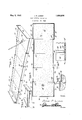
- Figure 1 is a perspective view of my improved golf putting' device in extended or set up position.
- Figure 2 is a top plan view of the same.
- Figure 3 is a perspective view of the device in collapsed position when not in use.
- Figure 4 is a fragmentary top plan view showing the. inter-engaging means between twoof the intermediate sections.
- Fi re 5 is an enlarged detail vertical lon- 50' gitu inal sectional view through the meetside walls 1313, together with an upstand- 0'0 ing end wall 14 which is of a hei ht greater than the height of the side wa s 13-13.
- the free ends of the side walls 13-13 have angle members 1515 secured thereto, one
- the endsection 11 embodies a flat bottom wall 16 and upstanding side walls 17-17, 7e
- Each of the intermediate or fairway sections 20 includes a flat bottom wall 21 and upstanding side walls 22, while fixed to the left end of the side walls 22 of each interto mediate section isone of the flanges of angle members 23.
- the attaching flange of the angle members 23 is secured to the inner side of the side wall while the other flange thereof extends outwardly for a distance just beyond the lane of the outer face of the side .walls.
- T e oppositeor right end of each intermediate section 20 is provided with angle members 24 which have their attaching flanges fitting against the outer side of the side walls 22 with the other flan e extending inwardl for a distance slightly beyond the plane 0 the inner side of the side wall.
- the section 10 When the intermediate sections 20 are fully extended the section 10 is connected to the narrowest sec-' tions 20 so that the angle members 15 engage the angle members 25 which brings the bottom 12 of the section 10 on the same plane as the bottom of the other sections. It will be seen that when the sections are all extended and arranged in end to end relation, there is provided an enclosed putting area within which a golf ball may be putted without fear of the same rolling out of bounds.
- the teesection 11 has a pocketor hole 26 provided in the bottom 16 and it will be seen that by placing a golf ball upon the bottom 12 of the tee section 10, a player with a golf putter in hand may strike the ball causing the same to roll true over the flat bottoms of the Various sections with the object of causing the ball to roll into the ocket or opening 26.
- any particular material from which the device may be constructed I find it ractical to employ sheets of card board or 0t er like material for the bottoms of the several sections, the to surfaces of which are covered by a layer 6 horse hair composition, felt or the like 27. This surface covering imparts to the device the features of a natural putting green.
- a golf putting device comprising a pair of end sections and a plurality of intermediate sections capable of being nested within one of said end sections, while the other of said end sections is adapted to be inverted and placed over the end section in which said intermediate sections are to be nested, all of said sections adapted to be placed end to end to produce a putting surface, and interengaging means between the meeting ends of said sections for holding the same against accidental creeping when the sections are in end to end position.
- a golf putting device comprising a pair of substantially identical end sections, and a plurality of intermediate sections of gradually decreasing width from one end section to the other, all of said sections having flat bottoms, and side walls, while the end sections are also provided with end walls, said intermediate sections adapted to be nested one within the other and the entire nested intermediate sections in turn capable of being housed in one of said end sections, whilethe other end section is adapted to fit over the end section having the nested intermediate sec-' tions therein.
- a golf putting device comprising a plurality of separable sections having flat bottom walls and upstanding side walls, and
Landscapes
- Engineering & Computer Science (AREA)
- Multimedia (AREA)
- Golf Clubs (AREA)
Description
May 3, 1932- J. P. LUDDY GOLF PUTTING APPARATUS Filed Dec. 26, 193D JAMES F? LUDW. Bylgg A tlorney Patented May 3, 1932 UNITED STATES I. BUDDY, F BROAD BROOK, CONNECTICUT GOLF PUTTING APPARATUS Application filed. December 26, 1880. Serial No. 501,888.
This invention relates to improvements in golf putting apparatus and has particular reference to such devices for indoor use.
The primary object of the invention resides in the sectional golf putting device which may be colla sed into a compact structure to enable shipping and storing in a minimum amount of space when not in use and which may be extended for use to provide an elon ated putting green or mat.
Another 0 ject of the'invent-ion is to provide a collapsible putting device which when extended for use presents a smooth and even putting surface to assure accurate and true putting of a old ball thereon, and which will be found lielpful to devotees of the outdoor game of golf in practicing putting indoors for the improvement of their outdoor p A further object is the provision of a golf putting. device which embodies a plurality of sections which may be extended as to lie end toend, but which may be also collapsed so that the intermediate sections are housed or nested within the two end sections.
A still further object of the invention is to provide a simple and inexpensive collapsible. putting device for indoor use, and which may be easily and quickly set up for use or collapsed when not in use.
. With these and other objects in view, the invention resides in the certain novel con-' struction, combination and arrangement of parts, the essential features of which are hereinafter fully described, are particularly pointed out in the appended claims, and are illustrated in the accompanying drawings, in which:
Figure 1 is a perspective view of my improved golf putting' device in extended or set up position.
Figure 2 is a top plan view of the same.
Figure 3 is a perspective view of the device in collapsed position when not in use.
Figure 4 is a fragmentary top plan view showing the. inter-engaging means between twoof the intermediate sections.
Fi re 5 is an enlarged detail vertical lon- 50' gitu inal sectional view through the meetside walls 1313, together with an upstand- 0'0 ing end wall 14 which is of a hei ht greater than the height of the side wa s 13-13. The free ends of the side walls 13-13 have angle members 1515 secured thereto, one
of the flanges of the angle members embracing the outer sides of the side walls .while the other flange extends inwardly for a purpose 'to be presently explained.
The endsection 11 embodies a flat bottom wall 16 and upstanding side walls 17-17, 7e
together with an upstanding end wall '18, the latter being of-a height greater than the side walls 17-17. The free ends ofthe side walls 17-1 7 are provided with angle members.19' 19, one of theflanges of each angle member is secured to the exterior side of theside walls, while the other flange extends inwardly.
By reference to Figure 2 of the drawings, it will be noted that the inwardly extendin flanges of the angle members'1515 exten inwardly a greater distance than the similar flanges of the angle members 19'19 to compensate for the engagement of certain of the intermediate sections 20 which will now be described.
Each of the intermediate or fairway sections 20 includes a flat bottom wall 21 and upstanding side walls 22, while fixed to the left end of the side walls 22 of each interto mediate section isone of the flanges of angle members 23. The attaching flange of the angle members 23 is secured to the inner side of the side wall while the other flange thereof extends outwardly for a distance just beyond the lane of the outer face of the side .walls. T e oppositeor right end of each intermediate section 20 is provided with angle members 24 which have their attaching flanges fitting against the outer side of the side walls 22 with the other flan e extending inwardl for a distance slightly beyond the plane 0 the inner side of the side wall. This construction is true with all sections except the intermediate section which con tion 11 when the device is in collapsed po-' sition, as shown in Figure 3 of the drawings. When in such position, the end section 12 is lifted free of the adjacent intermediate section 20 and the said section 12 inverted and fitted over the section 11 to provide a cover for completely housing the nested intermediate sections. When in such osition, the device may be compactly stored in a mini mum amount of space and permits easy han-= dling and shipping of the device.
Assuming that the sections are in collapsed position as shown in Figure 3 and the end section 12 is removed from its covering position. It is now possible to slide the intermediate sections 20 outward beyond one end of the section 11 to cause the intermediate section to assume an extensive position. When fully pulled out the angle members 19 of the end section 11 interengage with the angle members 23 of the next adiacent intermediate section, while the meeting ends of the other intermediate sections are limited in their extension by inter-engagement of the angle bars 23 and 24. It will be understood that when nested, the bottoms of the sections are disposed one upon the other, but when pulled out the sections drop so that the bottoms 21 and 16 of the end section are on the same horizontal plane, and the adjacent edges are in meeting contact so as to produce a continuous putting surface. When the intermediate sections 20 are fully extended the section 10 is connected to the narrowest sec-' tions 20 so that the angle members 15 engage the angle members 25 which brings the bottom 12 of the section 10 on the same plane as the bottom of the other sections. It will be seen that when the sections are all extended and arranged in end to end relation, there is provided an enclosed putting area within which a golf ball may be putted without fear of the same rolling out of bounds. The teesection 11 has a pocketor hole 26 provided in the bottom 16 and it will be seen that by placing a golf ball upon the bottom 12 of the tee section 10, a player with a golf putter in hand may strike the ball causing the same to roll true over the flat bottoms of the Various sections with the object of causing the ball to roll into the ocket or opening 26.
Although have not specified any particular material from which the device may be constructed I find it ractical to employ sheets of card board or 0t er like material for the bottoms of the several sections, the to surfaces of which are covered by a layer 6 horse hair composition, felt or the like 27. This surface covering imparts to the device the features of a natural putting green.
Although-I have not shown or described any hazards which may be placed between the putting tee 10 and the green tee 11, nevertheless such obstacles may be placed at different positions therebetween, and conveniently stored when the sections are in collapsed or nested positions.
From the foregoing description, it will be seen that when the device is set up for use, players may compete in endeavoring to roll the olf ball in the hole 26 with the least numher of shots, or the device may be used for practice by golf enthusiasts for the improvement of their outdoor ame.
While I have shown and escribed what I deem to be the most desirable embodiment of my invention, it will be understood that various changes may be resorted to if desired as come within the scope of the appended claims.
Having thus described the invention, what I claim as new and desire to secure by Letters Patent is 1. A golf putting device comprising a pair of end sections and a plurality of intermediate sections capable of being nested within one of said end sections, while the other of said end sections is adapted to be inverted and placed over the end section in which said intermediate sections are to be nested, all of said sections adapted to be placed end to end to produce a putting surface, and interengaging means between the meeting ends of said sections for holding the same against accidental creeping when the sections are in end to end position.
2. A golf putting device comprising a pair of substantially identical end sections, and a plurality of intermediate sections of gradually decreasing width from one end section to the other, all of said sections having flat bottoms, and side walls, while the end sections are also provided with end walls, said intermediate sections adapted to be nested one within the other and the entire nested intermediate sections in turn capable of being housed in one of said end sections, whilethe other end section is adapted to fit over the end section having the nested intermediate sec-' tions therein.
3. A golf putting device comprising a plurality of separable sections having flat bottom walls and upstanding side walls, and
tions when the flat bottom Walls are placed 5 end to end.
In testimony whereof I afiix my signature.
JAMES P. LUDDY.
Priority Applications (1)
| Application Number | Priority Date | Filing Date | Title |
|---|---|---|---|
| US504923A US1856816A (en) | 1930-12-26 | 1930-12-26 | Golf putting apparatus |
Applications Claiming Priority (1)
| Application Number | Priority Date | Filing Date | Title |
|---|---|---|---|
| US504923A US1856816A (en) | 1930-12-26 | 1930-12-26 | Golf putting apparatus |
Publications (1)
| Publication Number | Publication Date |
|---|---|
| US1856816A true US1856816A (en) | 1932-05-03 |
Family
ID=24008272
Family Applications (1)
| Application Number | Title | Priority Date | Filing Date |
|---|---|---|---|
| US504923A Expired - Lifetime US1856816A (en) | 1930-12-26 | 1930-12-26 | Golf putting apparatus |
Country Status (1)
| Country | Link |
|---|---|
| US (1) | US1856816A (en) |
Cited By (17)
| Publication number | Priority date | Publication date | Assignee | Title |
|---|---|---|---|---|
| US2456813A (en) * | 1947-06-20 | 1948-12-21 | Omar A Cavins | Golf putting device |
| US2827299A (en) * | 1954-08-12 | 1958-03-18 | Jewett M Dean | Miniature golf game |
| US3011791A (en) * | 1960-06-20 | 1961-12-05 | Clarence E Page | Golf putting game device |
| US3038726A (en) * | 1959-06-05 | 1962-06-12 | Arthur J Hesidence | Practice putting apparatus |
| US3727917A (en) * | 1971-09-29 | 1973-04-17 | Lean G Mac | Variable contour golf putting device |
| US3831949A (en) * | 1973-01-09 | 1974-08-27 | G Henning | Variable contour miniature golf device |
| USD243777S (en) | 1975-02-21 | 1977-03-22 | Lewis Frederick T | Putting target unit for a golf game apparatus |
| US4596391A (en) * | 1985-11-01 | 1986-06-24 | Carolan Jr Leo P | Portable golf game |
| US5108101A (en) * | 1991-03-04 | 1992-04-28 | Postula Victor A | Method of playing a lag and bump putting game |
| US5413344A (en) * | 1994-05-03 | 1995-05-09 | Darden; Hardy F. | Portable bumper golf system |
| US5429368A (en) * | 1994-06-03 | 1995-07-04 | Adams; Thomas R. | Portable practice putting device |
| US5516109A (en) * | 1995-01-06 | 1996-05-14 | Desjardins; Pierre | Modular and interchangeable golf putting platform |
| US6152830A (en) * | 1999-06-03 | 2000-11-28 | Archie; Samuel L. J. | Putting practice system |
| US6623371B2 (en) | 2001-02-02 | 2003-09-23 | Jerry A. Corcoran | Golf putting and ball return system |
| US20100151954A1 (en) * | 2008-12-12 | 2010-06-17 | Mark Chelak | Portable bowling game kit |
| US20130045817A1 (en) * | 2011-03-29 | 2013-02-21 | Kevin Irwin | Portable golf swing training platform with video display compartment |
| US8951135B1 (en) | 2011-02-16 | 2015-02-10 | Reynolds W. Guyer | Tabletop miniature golf game |
-
1930
- 1930-12-26 US US504923A patent/US1856816A/en not_active Expired - Lifetime
Cited By (18)
| Publication number | Priority date | Publication date | Assignee | Title |
|---|---|---|---|---|
| US2456813A (en) * | 1947-06-20 | 1948-12-21 | Omar A Cavins | Golf putting device |
| US2827299A (en) * | 1954-08-12 | 1958-03-18 | Jewett M Dean | Miniature golf game |
| US3038726A (en) * | 1959-06-05 | 1962-06-12 | Arthur J Hesidence | Practice putting apparatus |
| US3011791A (en) * | 1960-06-20 | 1961-12-05 | Clarence E Page | Golf putting game device |
| US3727917A (en) * | 1971-09-29 | 1973-04-17 | Lean G Mac | Variable contour golf putting device |
| US3831949A (en) * | 1973-01-09 | 1974-08-27 | G Henning | Variable contour miniature golf device |
| USD243777S (en) | 1975-02-21 | 1977-03-22 | Lewis Frederick T | Putting target unit for a golf game apparatus |
| US4596391A (en) * | 1985-11-01 | 1986-06-24 | Carolan Jr Leo P | Portable golf game |
| US5108101A (en) * | 1991-03-04 | 1992-04-28 | Postula Victor A | Method of playing a lag and bump putting game |
| US5413344A (en) * | 1994-05-03 | 1995-05-09 | Darden; Hardy F. | Portable bumper golf system |
| US5429368A (en) * | 1994-06-03 | 1995-07-04 | Adams; Thomas R. | Portable practice putting device |
| US5516109A (en) * | 1995-01-06 | 1996-05-14 | Desjardins; Pierre | Modular and interchangeable golf putting platform |
| US6152830A (en) * | 1999-06-03 | 2000-11-28 | Archie; Samuel L. J. | Putting practice system |
| US6623371B2 (en) | 2001-02-02 | 2003-09-23 | Jerry A. Corcoran | Golf putting and ball return system |
| US20100151954A1 (en) * | 2008-12-12 | 2010-06-17 | Mark Chelak | Portable bowling game kit |
| US7744478B1 (en) * | 2008-12-12 | 2010-06-29 | Mark Chelak | Portable bowling game kit |
| US8951135B1 (en) | 2011-02-16 | 2015-02-10 | Reynolds W. Guyer | Tabletop miniature golf game |
| US20130045817A1 (en) * | 2011-03-29 | 2013-02-21 | Kevin Irwin | Portable golf swing training platform with video display compartment |
Similar Documents
| Publication | Publication Date | Title |
|---|---|---|
| US1856816A (en) | Golf putting apparatus | |
| US8702528B1 (en) | Putting practice apparatus | |
| US9687709B2 (en) | Multi-configurable bean bag game and method of game play | |
| US9248357B2 (en) | Bean bag tossing game | |
| US4596391A (en) | Portable golf game | |
| US4877250A (en) | Portable golf putting course | |
| US5429368A (en) | Portable practice putting device | |
| US20120065004A1 (en) | Ball Tossing Skills Game and Methods of Playing Same | |
| US3504914A (en) | Combined target,disk markers,and ball game | |
| US4098507A (en) | Portable miniature golf game | |
| US20200230478A1 (en) | Throwing game apparatus & method | |
| US8807565B2 (en) | Wheel game with holes | |
| US5954590A (en) | Golf putting aid or game | |
| US9044665B2 (en) | Table ball game for opposite ended play using a single ball | |
| US20090200742A1 (en) | Game Apparatus for playing tossing game | |
| US20220339509A1 (en) | Portable game assembly and methods for play | |
| US20120235353A1 (en) | Game table and games for play thereupon | |
| US5108101A (en) | Method of playing a lag and bump putting game | |
| US2809040A (en) | Pocketed ball game apparatus | |
| US20150335993A1 (en) | Game Apparatus And Method Of Play | |
| US4630828A (en) | Sand trap practice device | |
| US10207165B2 (en) | Bumper golf game system and related methods | |
| US20070135224A1 (en) | 1-4 Player bulls eye putting game | |
| US20150209637A1 (en) | Golf ball putting game | |
| US10112106B1 (en) | Gaming kit for use with rolling target tossing game |