US1856813A - Snap fastener stud member - Google Patents
Snap fastener stud member Download PDFInfo
- Publication number
- US1856813A US1856813A US397399A US39739929A US1856813A US 1856813 A US1856813 A US 1856813A US 397399 A US397399 A US 397399A US 39739929 A US39739929 A US 39739929A US 1856813 A US1856813 A US 1856813A
- Authority
- US
- United States
- Prior art keywords
- head
- stud
- screw
- snap fastener
- cap
- Prior art date
- Legal status (The legal status is an assumption and is not a legal conclusion. Google has not performed a legal analysis and makes no representation as to the accuracy of the status listed.)
- Expired - Lifetime
Links
Images
Classifications
-
- F—MECHANICAL ENGINEERING; LIGHTING; HEATING; WEAPONS; BLASTING
- F16—ENGINEERING ELEMENTS AND UNITS; GENERAL MEASURES FOR PRODUCING AND MAINTAINING EFFECTIVE FUNCTIONING OF MACHINES OR INSTALLATIONS; THERMAL INSULATION IN GENERAL
- F16B—DEVICES FOR FASTENING OR SECURING CONSTRUCTIONAL ELEMENTS OR MACHINE PARTS TOGETHER, e.g. NAILS, BOLTS, CIRCLIPS, CLAMPS, CLIPS OR WEDGES; JOINTS OR JOINTING
- F16B21/00—Means for preventing relative axial movement of a pin, spigot, shaft or the like and a member surrounding it; Stud-and-socket releasable fastenings
- F16B21/06—Releasable fastening devices with snap-action
- F16B21/07—Releasable fastening devices with snap-action in which the socket has a resilient part
- F16B21/073—Releasable fastening devices with snap-action in which the socket has a resilient part the socket having a resilient part on its inside
-
- Y—GENERAL TAGGING OF NEW TECHNOLOGICAL DEVELOPMENTS; GENERAL TAGGING OF CROSS-SECTIONAL TECHNOLOGIES SPANNING OVER SEVERAL SECTIONS OF THE IPC; TECHNICAL SUBJECTS COVERED BY FORMER USPC CROSS-REFERENCE ART COLLECTIONS [XRACs] AND DIGESTS
- Y10—TECHNICAL SUBJECTS COVERED BY FORMER USPC
- Y10T—TECHNICAL SUBJECTS COVERED BY FORMER US CLASSIFICATION
- Y10T24/00—Buckles, buttons, clasps, etc.
- Y10T24/45—Separable-fastener or required component thereof [e.g., projection and cavity to complete interlock]
- Y10T24/45225—Separable-fastener or required component thereof [e.g., projection and cavity to complete interlock] including member having distinct formations and mating member selectively interlocking therewith
- Y10T24/4588—Means for mounting projection or cavity portion
- Y10T24/45942—Means for mounting projection or cavity portion having threaded formation
Definitions
- My invention aims toprovide improvements in separable fastener studs.
- Figure 1 is a section showing one form of stud attached to a stud support by a wood screw;
- Fig. 2 is a section showing a slightly different form of device adapted particularly for studs attached by a drive screw;
- Fig. 3 includes a plan and side elevation, respectively, of the stud shown in Fig. 1;
- Fig. 4 is a section of a third form of stud.
- Fig. 5 is a part section and part elevation of a stud like that shown in Fig. 4, but with the cap split to provide a yieldable head.
- My invention is particularly adapted for stud members of separable fasteners which are attached to rigid supporting structures by means of screws.
- the screw-s are made of steel because that metal is strong and durable and the caps and sealing pieces are. made of brass because that metal is particularly adapted to be drawn into the shape desired. Furthermore, brass or other similarly useful metal will not rust.
- a stud which has a sheet metal cap provided with a base l, a neck 2 and a head 3.
- the head and neck are shaped to cooperate with a suitable socket, not shown.
- An aperture 4, surrounded by a wall 5, is provided in the central portion of the head for purposes hereinafter described.
- An attaching element in the form of a ⁇ wood screw has a head 6 secured to the base 1 of the stud in the usual manner and the threaded shank 7 extends from the head 6 into the support 8.
- the head 6 is provided with a tool-receiving depression which is illustrated (Fig. 1) in the form of a screwdriver slot 9.
- This slot 9 would behexposed through the opening 4 in the head of the cap for reception of a screw-driver, except for the fact that I prefer to close the aperture 4 and conceal the head 6 of the attaching ⁇ element by means of the sealing part 10.
- the sealing part l() is shown as being cup-shaped with the wall 11 tightly engaging the wall 5 surrounding the aperture 4 to hold it in place. This sealing part conceals the head 6 of the attaching element so that if the head becomes rusted it will not be exposed to view when the stud is attached.
- the sealing part 10 is provided to exclude Water and moisture from the head G.
- the bottom of the cup-shaped sealing part 10 is provided with a depending portion 12 which fits into the slot 9 and also provides a groove 13 into which a screw-driver may be inserted to turn the screw into or out of engagement with the support 8.
- the stud illustrated in Fig. 2 is similar to that shown in Figs. 1 and 3, except that the screw shank 14 is in the nature of a drive screw.
- the sealing part 15 is without a depending portion to fit into the slot in the screw head because it is unnecessary when attaching the stud.
- the operator merely drives a screwdriver blade through the bottom of the sealing element into the underlying slot in the head of the screw. Then by turning the screw-driver in a contra-clockwise direction the drive screw may be turned out of the support.
- a stud construction wherein the sealing part is in the nature of a thin disc 16 which is shaped to fit the contour of the head of the attaching element. This disc 16 is clamped between the base 1 of the cap and the head 6 of the attaching element and thereby covers the head 6 and keeps water and moisture from coming in Contact therewith.
- Fig. 5 I have shown the same type and construction of stud as shown in Fig. 4, eX- cept that I have divided the head 3, neck 2 and wall 5 surrounding the aperture 4 by slits 17 to permit contraction and expansion of the stud head for yieldable engagement with a rigid socket.
- Vhat I claim is:
- a snap fastener member comprising, -in combination, ran apertured cap lhaving means for engagement with a cooperating fastener member, said cap also having a base, anattaching-element having a head seoured ⁇ withinthe base of said cap andfa threaded-shank portion projecting from the head 0f said attaohing element for securing-thesnap fastener element to a support, means providing a depression in the head of'said4 attaching ⁇ element, a third part independent of the cap and the attaching element and secured between the cap and the head 0f the attaching element and *concealing the head of theattaching ⁇ element, and said thirdpart having a portion adjacent to the ⁇ depression in the head of theattaehing element which permits insertion of a tool into said depression for rotation of said attaching element when it is desirable to remove the fastener member from a supporting structure.
Landscapes
- Engineering & Computer Science (AREA)
- General Engineering & Computer Science (AREA)
- Mechanical Engineering (AREA)
- Joining Of Building Structures In Genera (AREA)
Description
May 3,v 1932. W l. JONES 1,85%,813
SNAP FASTENER si* MMMMMM ER Patented May 3, 1932 WALTER I. JONES, OF ARLINGTON, MASSACHUSETTS, ASSIGNOR TO UNITED-CARR FASTENER CORPORATION, MASSACHUSETTS OF CAMBRIDGE, MASSACHUSETTS, A CORPORATION 0F SNAP FASTENER STUD MEMBER Application led October 4, 1929. Serial No.. 397,399.
My invention aims toprovide improvements in separable fastener studs.
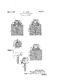
In the drawings, which illustrate preferred embodiments of my invention 5, Figure 1 is a section showing one form of stud attached to a stud support by a wood screw;
Fig. 2 is a section showing a slightly different form of device adapted particularly for studs attached by a drive screw;
Fig. 3 includes a plan and side elevation, respectively, of the stud shown in Fig. 1;
Fig. 4 is a section of a third form of stud; and
Fig. 5 is a part section and part elevation of a stud like that shown in Fig. 4, but with the cap split to provide a yieldable head.
My invention is particularly adapted for stud members of separable fasteners which are attached to rigid supporting structures by means of screws. The screw-s are made of steel because that metal is strong and durable and the caps and sealing pieces are. made of brass because that metal is particularly adapted to be drawn into the shape desired. Furthermore, brass or other similarly useful metal will not rust.
Each of the studs which I have illustrated in the drawings are assembled from three separate pieces, and vary only in form to suit the particular use of the stud.
Referring now to Figs. 1 and 3 of the drawings, I have illustrated a stud which has a sheet metal cap provided with a base l, a neck 2 and a head 3. The head and neck are shaped to cooperate with a suitable socket, not shown. An aperture 4, surrounded by a wall 5, is provided in the central portion of the head for purposes hereinafter described.
An attaching element in the form of a` wood screw has a head 6 secured to the base 1 of the stud in the usual manner and the threaded shank 7 extends from the head 6 into the support 8. The head 6 is provided with a tool-receiving depression which is illustrated (Fig. 1) in the form of a screwdriver slot 9. This slot 9 would behexposed through the opening 4 in the head of the cap for reception of a screw-driver, except for the fact that I prefer to close the aperture 4 and conceal the head 6 of the attaching` element by means of the sealing part 10. In Figs. 1 and 3 the sealing part l() is shown as being cup-shaped with the wall 11 tightly engaging the wall 5 surrounding the aperture 4 to hold it in place. This sealing part conceals the head 6 of the attaching element so that if the head becomes rusted it will not be exposed to view when the stud is attached. Furthermore, the sealing part 10 is provided to exclude Water and moisture from the head G.
The bottom of the cup-shaped sealing part 10 is provided with a depending portion 12 which fits into the slot 9 and also provides a groove 13 into which a screw-driver may be inserted to turn the screw into or out of engagement with the support 8.
The stud illustrated in Fig. 2 is similar to that shown in Figs. 1 and 3, except that the screw shank 14 is in the nature of a drive screw. The sealing part 15 is without a depending portion to fit into the slot in the screw head because it is unnecessary when attaching the stud. However, when it is desirable to remove the fastener from the support 8 the operator merely drives a screwdriver blade through the bottom of the sealing element into the underlying slot in the head of the screw. Then by turning the screw-driver in a contra-clockwise direction the drive screw may be turned out of the support.
In Fig. 4, I have shown a stud construction wherein the sealing part is in the nature of a thin disc 16 which is shaped to fit the contour of the head of the attaching element. This disc 16 is clamped between the base 1 of the cap and the head 6 of the attaching element and thereby covers the head 6 and keeps water and moisture from coming in Contact therewith.
In Fig. 5, I have shown the same type and construction of stud as shown in Fig. 4, eX- cept that I have divided the head 3, neck 2 and wall 5 surrounding the aperture 4 by slits 17 to permit contraction and expansion of the stud head for yieldable engagement with a rigid socket.
While I have illustrated and described IOL FII
certain specific embodiments of my invention, I do not wish to be limited thereby, as the scope of my invention is best defined in the following claim.
Vhat I claim is:
A snap fastener member comprising, -in combination, ran apertured cap lhaving means for engagement with a cooperating fastener member, said cap also having a base, anattaching-element having a head seoured`withinthe base of said cap andfa threaded-shank portion projecting from the head 0f said attaohing element for securing-thesnap fastener element to a support, means providing a depression in the head of'said4 attaching` element, a third part independent of the cap and the attaching element and secured between the cap and the head 0f the attaching element and *concealing the head of theattaching` element, and said thirdpart having a portion adjacent to the` depression in the head of theattaehing element which permits insertion of a tool into said depression for rotation of said attaching element when it is desirable to remove the fastener member from a supporting structure.
In testimony whereof, I have signed myname to this .specification` VALTER I. JONES.
Priority Applications (1)
| Application Number | Priority Date | Filing Date | Title |
|---|---|---|---|
| US397399A US1856813A (en) | 1929-10-04 | 1929-10-04 | Snap fastener stud member |
Applications Claiming Priority (1)
| Application Number | Priority Date | Filing Date | Title |
|---|---|---|---|
| US397399A US1856813A (en) | 1929-10-04 | 1929-10-04 | Snap fastener stud member |
Publications (1)
| Publication Number | Publication Date |
|---|---|
| US1856813A true US1856813A (en) | 1932-05-03 |
Family
ID=23571032
Family Applications (1)
| Application Number | Title | Priority Date | Filing Date |
|---|---|---|---|
| US397399A Expired - Lifetime US1856813A (en) | 1929-10-04 | 1929-10-04 | Snap fastener stud member |
Country Status (1)
| Country | Link |
|---|---|
| US (1) | US1856813A (en) |
Cited By (2)
| Publication number | Priority date | Publication date | Assignee | Title |
|---|---|---|---|---|
| US3166969A (en) * | 1963-03-27 | 1965-01-26 | Linton Mfg Co Inc | Wind musical instrument |
| DE29716398U1 (en) * | 1997-09-12 | 1998-01-02 | Stocksmeier, Eckard, Dr.med., 32657 Lemgo | Notebook pen |
-
1929
- 1929-10-04 US US397399A patent/US1856813A/en not_active Expired - Lifetime
Cited By (2)
| Publication number | Priority date | Publication date | Assignee | Title |
|---|---|---|---|---|
| US3166969A (en) * | 1963-03-27 | 1965-01-26 | Linton Mfg Co Inc | Wind musical instrument |
| DE29716398U1 (en) * | 1997-09-12 | 1998-01-02 | Stocksmeier, Eckard, Dr.med., 32657 Lemgo | Notebook pen |
Similar Documents
| Publication | Publication Date | Title |
|---|---|---|
| US3347293A (en) | Removable bit construction for screwdrivers and the like | |
| US2565636A (en) | Spring latching fastener | |
| US2963253A (en) | Mounting means for electrical outlet boxes | |
| GB1136897A (en) | Improvements in or relating to quick release fasteners | |
| US2627778A (en) | Screw and cap | |
| US2798277A (en) | Separable fastener | |
| US2203397A (en) | Plate attaching device | |
| US2319726A (en) | Suction cup structure | |
| US1856813A (en) | Snap fastener stud member | |
| US2360647A (en) | Fastener secured installation and fastener therefor | |
| US1798838A (en) | Outlet box | |
| US2451991A (en) | Fastener | |
| GB557409A (en) | Improvements in and relating to fasteners for use with apertured supports | |
| US2378257A (en) | Fastening device | |
| US2259720A (en) | Nut and nut assembly | |
| US1997686A (en) | Fixture support | |
| US2225394A (en) | Fastening means | |
| US4781504A (en) | Trim clip | |
| US2422420A (en) | Closure device | |
| US2527707A (en) | Decorative candleholder | |
| US1634234A (en) | Fastener stud | |
| US1856814A (en) | Snap fastener | |
| US1481784A (en) | Screw stud for snap fasteners | |
| US2407815A (en) | Shiftable cowling and like socket fastener member | |
| US1062921A (en) | Curtain-fastener for automobiles. |