US1856784A - Fluid operated tool - Google Patents
Fluid operated tool Download PDFInfo
- Publication number
- US1856784A US1856784A US266794A US26679428A US1856784A US 1856784 A US1856784 A US 1856784A US 266794 A US266794 A US 266794A US 26679428 A US26679428 A US 26679428A US 1856784 A US1856784 A US 1856784A
- Authority
- US
- United States
- Prior art keywords
- piston
- valve
- exhaust
- fluid
- passageway
- Prior art date
- Legal status (The legal status is an assumption and is not a legal conclusion. Google has not performed a legal analysis and makes no representation as to the accuracy of the status listed.)
- Expired - Lifetime
Links
- 239000012530 fluid Substances 0.000 title description 78
- 229910000831 Steel Inorganic materials 0.000 description 7
- 239000010959 steel Substances 0.000 description 7
- 238000005520 cutting process Methods 0.000 description 5
- 238000010276 construction Methods 0.000 description 2
- 238000007664 blowing Methods 0.000 description 1
- 239000000463 material Substances 0.000 description 1
- 230000002093 peripheral effect Effects 0.000 description 1
- 230000008092 positive effect Effects 0.000 description 1
- 239000011435 rock Substances 0.000 description 1
- 230000000153 supplemental effect Effects 0.000 description 1
Images

Classifications
-
- E—FIXED CONSTRUCTIONS
- E21—EARTH OR ROCK DRILLING; MINING
- E21B—EARTH OR ROCK DRILLING; OBTAINING OIL, GAS, WATER, SOLUBLE OR MELTABLE MATERIALS OR A SLURRY OF MINERALS FROM WELLS
- E21B21/00—Methods or apparatus for flushing boreholes, e.g. by use of exhaust air from motor
- E21B21/01—Arrangements for handling drilling fluids or cuttings outside the borehole, e.g. mud boxes
Definitions
- the present invention relates to valve vmech,- anism for pneumatic tools, and the object is to provide novel and effective means for stopping the pist-on and delivering air or other motive fluid at substantially line pressure to the bore of the steel or tool being operated on by the piston. It is thus peculiarly useful for blowing out accumulated cuttings from the bottom of a hole being drilled.
- Figure 1 is a longitudinal sectional view through a rock drill showing the novel mechanism with the automatic valve and the piston in normally operative or working condition, 5 this view being a bit diagrammatic in character in illustrating various of the passageways in the same longitudinal plane.
- Figure 2 is a similar view showing the mechanism with the automatic valve stopped
- Figure. 4 is a. horizontal sectional view on the line 4 4 of Figure 3.
- Figure 6 is a cross sectional view on the line 6 6 of Figure 3.
- Figure 4' is a side elevation of the fluid operated controlling valve.
- Figure S is an end elevation of the same.
- Figure 9 is a longitudinal sectional view of the cage for the fluid operated valve.
- Figure is an end elevation thereof.
- the general structure of the tool and its automatic distributing valve is the same as that disclosed in the application of Edward l F. Terry, Jr.. Ser. No. 167,764, Patent 1574, 302, August 26.v 1930.
- a cylinder is illustrated, containing a piston chamber 5, in which a. reciprocatory piston 6 operates, this piston having a hammer extension 7 on one side of the cylinder 4, and preferably integral therewith is lo-
- Figure 5 is a detail sectional View through cated avalve lcasing 8 having spaced head chambers 9 and 10 connected by a reduced bore 11.
- the outer end of the head chamber 9 is provided with an annular vchannel 12 that communicates with the rear end of the piston chamber 5, through a straight short passageway Or port 13.
- the inner end of the head chamber 9 has communication with an intermediate portion of the piston chamber by a straight port 14.
- the head chamber 9 has an internal channel 15, from which opens an exhaust outlet 16 to atmosphere.
- the head chamber 10 is ⁇ somewhat longer than the head chamber 9 and of smaller diameter. It is provided at its front end with an annular channel 17 that communicates by means of a short port 18 ⁇ with the front end of the piston chamber 5 in advance of the piston 6.
- the rear end of the head chamber 10 has a straight port connection 19 with an intermediate portion of the piston chamber 5 in advance of the port 14.
- annular channel 20 Between the ports 18 and 19 there is formed in the head chamber 10 an annular channel 20, with which an exhaust port 21 communicates, said exhaust port being between the ports 18 and 19. Between the ports 19 and 21 there is formed in the head chamber 10 an annular channel 22, from which leads an exhaust outlet 23 opening to atmosphere.
- a reciprocatory valve is located in the valve casing 8. and preferably consists of two sections.
- This valve has terminal heads 24 and 25 that reciprocate in the respective head chambers 9 and 10.
- the head 24 therefore has a greater diameter than the head 25.
- Projecting from each head are reduced shank extensions 26 and 27 that operate in the bore 11 and abut against each other.
- the heads are hollow and are open-ended, and the shank 26-27 is provided with a bore 28 communicating with the hollow heads.
- the head 24 has a peripheral end pressure surface 29 and an inset pressure surface section 30.
- the end of the head 24 is preferably provided with an inwardly extending annular fia-nge 31, the inner surface 32 of which obviously equalizes the pressure on an equivalent portion of the surface 30.
- the inner end face 33 of t-he head 24 constitutes a pressure surface opposed to the pressure surfaces 29 and 30.
- the head 25 similarly has an annular end pressure surface section 34 and an inset pressure surface 35. It is provided with an opposing pressure surface 36. Said head furthermore has an annular channel 37 forming a flange 38.
- the plug 39 is hollow and forms a supply port 41 leading from a throttle valve casing 42, in which is a suitable rotatable throttle valve 43.
- the structure constitutes a differential valve, and its operation is substantially as follows.
- the'piston is at the forward end of its stroke, and the valve has been shifted to a forward position.
- the motive fluid entering through the port 41 of the plug 39 will pass behind the piston as the same returns from the end of its cushioned stroke, and drives said piston forwardly.
- the motive fluid in advance of the piston can exhaust freely through the ports 19 and 21, and by way of the head chamber 10 to the exhaust outlet 23.
- the flange 38 is in an intermediate position with respect to the. channel 22, vso that both ports 19 and 21 are open to the exhaust outlet 23.
- valve is held in its forward position by pressure against the rear end surfaces 29 and 30, which surfaces minus the surface 32, are suflicient to overcome the pressure against the opposite face 35 of the head 25, material pressure against the surface 34 being cut 0E by the Contact of said surface against the end of the plug 40.
- the valve therefore remains in its forward position until the rear end of the piston 6 uncovers the port 14. Then this occurs, additional pressure is brought against the surface 33 and the area of this surface plus the area of the surface 35 is suflicient to overcome the pressure against the surfaces 29 and 30, so that the valve is shifted to the position shown in Figure 1.
- motive fluid in the front end of the and this steel is provided with the usual lonil gitudinal bore 46.
- the piston 6 and hammer extension 7 are provided with a longitudinal bore 47 that allows air'or other motive fluid to pass from the rear end of the piston chamber 5 through the piston and hammer extension and enter the bore 46 when the piston moves forwardly under the influence of the motive fluid behind it. As a consequence this fluid will ordinarily blow out the cuttings from the bottom of the' hole being drilled.
- the plug 40 is tubular in form, and constitutes a piston chamber 48 that opens into the head 7*- chamber 10 by reason of an opening 49 formed in the inner end of said plug 49.
- a reciprocatory piston 50 is mounted in the piston chamber 48, and has an inwardly extending stem 51 constituting a plunger' valve or plug that is adapted to enter the passageway 28 when the piston is moved to the inner end of the chamber 48.
- This piston and plug 51 thus constitute a fluid actuated valve for the purposes hereinafter explained.
- movement of the piston is limited by a stop stem 52 carried thereby and arranged to abut against the outer end wall of the piston chainber 48.
- the outer @'35 48 is open to atmospherethrough a plurality f -l of ports 53 that open into an annular groove 54 having communication with outlet ports 55 in the valve casing 8.
- the exhaust port 23 for the front end of the main piston chamber 5 passes through a valve casing 56 formed on one side of the main casing 8.
- a valve casing 56 formed on one side of the main casing 8.
- the valve is provided with a suitable handle 59, by which it can be turned either to a position to close the exhaust port 23, as shown in Figures 2 and 5, or to an open position to allow the free exhaust of the air in front of the piston 6 to atmosphere.
- a bypass passageway 60 leads from the exhaust conducting groove 22, with which the exhaust port 23 communicates, to an annular groove 6l formed on the exterior of the plug 40 and this groove 6l is in communication with the rear end of the piston chamber 48 by means of ports 62.
- a passageway 63 Extending from the rear end of the chamber 9 is a passageway 63 and extending from the rear end ofthe chamber l0 is a passageway 64, the two meeting at the valve 57.
- a passageway which when the valve is in open position as shown in Figure l affords communication between the passageways 63-64 and atmosphere and when the valve 57 is in closed position as illustrated in Figure 2, establishes communication between said passageway 63-64 and the passageway 60.
- rl ⁇ he plug 5l has a reduced portion 66 which as shown in' Figure 5 is adapted to 1nass through the end wall of the chamber 48 and the face of the piston 50 has grooves 67 that communicate with the groove formed by said reduced portion.
- valve 57 is closed the port 65 is cut off from atmosphere but serves to carry live air to the rear of the piston 50, thus insuring the positive action and holding the plug 5l.
- the valve 57 is open and the passageways 63 and 64 are thus open to atmosphere any air that may otherwise be trapped in front of the flange 38 or behind the head 24 can escape.V
- Vhat I claim is:
- a tool of the character set forth the combination with a cylinder member and a piston operating therein, of means for supplying motive fluid to the tool, an automatic valve for distributing the motive fluid to the piston to actuate it and including a passageway to one end of the piston, a fluid actuated valve for closing said passageway, means for permitting the exhaust from the same end of the piston, a valve for closing the exhaust permitting means and a by-passagew'ay for directing the exhaust when so interrupted to pass to and operate the fluid actuated valve.
- a tool of the character set forth the combination with a cylinder member having a piston chamber and a piston operating therein, of means for supplying motive fluid to the tool, an automatic valve for distributing the motive fluid to the ends of the piston chamber to operate the piston, means for permitting the exhaust from the front end of the piston to atmosphere, means for cutting ofi' the escape of exhaust to atmosphere, a fluid operated device for cutting off the supply of motive fluid from the automatic distributing valve to the front end of the piston chamber, and means for causing the exhaust when cut ofl ⁇ 1 from atmosphere to operate the said means for cutting off said supply.
- a tool c-f the character set forth the combination with a cylinder member having a piston chamber and a piston operating therein, of means for supplying motive fluid to the tool, an automatic valve for distributing the motive fluid to the ends of the piston chamber to operate the piston, means for permitting the exhaust from the front end of the piston to atmosphere, a valve for closing the exhaust, a fluid operated valve for preventing the supply of motive fluid from the automatic distributing valve to the front end of the piston, and a passageway for directing the exhaust fluid to the fluid operated valve when the exhaust to atmosphere is closed.
- a tool of the character set forth the combination with a cylinder member having a piston chamber and a piston operating in the chamber, an automatic valve for distributing the motive fluid to the piston chamber on opposite sides of the piston to actuate the latter, said valve having a passageway therethrough for delivering motive fluid to one end of the piston, and means for closing said passageway to prevent the delivery of such fluid to stop the valve and piston.
- a. tool of the character' set forth the combination with a cylinder member having a piston chamber and a piston operating in the chamber, an automatic valve for distributing the motive fluid to the piston chamber on opposite sides of the piston to actuate the latter, said valve having a passageway therethrough for delivering motive fluid to the front end of the piston, and means for closing said passageway to prevent the delivery of such fluid to stop the valve and stop the piston at the front end of its stroke.
- a tool of the character set forth the combination with a cylinder member having a piston chamber and a piston operating in the chamber, an automatic valve for distributing the motive fluid to the piston chamber on opposite sides of the piston to actuate the latter, said valve having a passageway therethrough for delivering motive fluid to the front end of the piston, a fluid actuated valve for closing said passageway in the automatic valve, to thereby stop the piston at the front end of its stroke, and means for directing fluid to the fluid' actuated valve to move it.
- valve mechanism for distributing the motive fluid to the piston to actuate it and including a passageway to one end of the piston, means for permitting the exhaust from the same end of the piston, and valve mechanism for closing said passageway and also closing the said exhaust, said valve mechanism also having a supplemental port open to atmosphere to relieve pressure against surfaces of the valve.
- a tool of the character set forth the combination with a cylinder member and' a piston operating therein, of means for supplying motive fluid to the tool, an automatic valve for distributing the motive fluid to the piston to actuate it and including a passageway to one end of the piston, a fluid actuated valve for closing said passageway, means for permitting the exhaust from the same end of the piston, a valve for closing the exhaust permitting means, a by-passageway for directing fluid from one end of the piston to the fluid actuated valve,
- a tool of the character set forth the combination with a cylinder member and a piston operating therein, of means for supplying motive fluid to the tool, an automatic valve for distributing the motive fluid to the piston to actuate it and including a passageway to one end of the piston, a fluid actuated valve for closing said passageway, means for permitting the exhaust from both ends of the piston, a valve for closing the exhaust permitting means, a by-passageway for directing the exhaust when so interrupted to pass to and operate the fluid actuated valve, and a .second by-passageway leading from the rear end of the piston to admit motive fluid to the fluid actuated valve for insuring its positive operation.
- a tool of the character set forth the combination with a cylinder member and a piston operating therein, of means for supplying motive Huid t the tool, an automatic valve for distributing the motive Huid to the piston to actuate it and including a passageway to one end of the piston, a Huid actuated valve for closing said passageway, means for permitting the exhaust from both ends of the piston, a valve for closing the exhaust permitting means, and a plurality of by-passageways for directing the exhaust and live air from opposite sides of the piston to the fluid actuated valve t0 move it to an active position.
- 0f means for supplying motive fluid to the tool, an automatic valve for distributing the motive fluid to the piston to actuate it and including a passageway to one end of the piston, a fluid actuated valve for closing said passageway, means for permitting the exhaust from both ends of the piston, a valve for closing the exhaust permitting means, and a plurality of by-passageways controlled by said exhaust valve for directing both the exhaust and live air from either side of the piston to the iuidy actuated valve to move it to an operative position.
Landscapes
- Engineering & Computer Science (AREA)
- Life Sciences & Earth Sciences (AREA)
- Geology (AREA)
- Mining & Mineral Resources (AREA)
- Mechanical Engineering (AREA)
- Physics & Mathematics (AREA)
- Environmental & Geological Engineering (AREA)
- Fluid Mechanics (AREA)
- General Life Sciences & Earth Sciences (AREA)
- Geochemistry & Mineralogy (AREA)
- Portable Nailing Machines And Staplers (AREA)
Description
May 3, 1932. G. c. PEARSON FLUID OPERATE TOOL 4 Sheets-Sheet 1 Filed April 2. 192e 'u S m M@ m .c vPV C V W. u G .muv am. mw N if wm. m. w MN MM .nw/9W l -m mwN whkhw. mm Mw .NR u.. wm mw www f l w y f l.\ i xivv k! X\\\I .ll. -Mmmn May 3, 1932.
G. c. PEARSON FLUID OPERATED TOOL Filed April 2. 1928 4 Sheets-Sheet 2v Gaaf/iv ai? Fwesaf May 3, 1932. G. c. PEARsoN FLUXD OPERATED TooL Filed April 2. 1928 4 Sheets-Sheet 3 mmv Nm ma uw P mm l@ May 3, 19
* G. c. PEARso-Nv FLUID OPERTED TOOL Filed April 2. 1928 Y ASheetsv-Sl'xee'kl 4 Gus rnv C ,qe-@Raon i P n) Patented May 3, 1932 UNITED STATES PATENT GUSTAV C. PEARSON, F DENVER, COLORADO, ASSIGNOR TO GARDNER-DENVER COM- PANY, OF DENVER, COLORADO, A CORPORATON OF DELAVJARE FLUID OPERATED TOOL Application led April 2, 1928. Serial No. 266,794.
The present invention relates to valve vmech,- anism for pneumatic tools, and the object is to provide novel and effective means for stopping the pist-on and delivering air or other motive fluid at substantially line pressure to the bore of the steel or tool being operated on by the piston. It is thus peculiarly useful for blowing out accumulated cuttings from the bottom of a hole being drilled.
In the accompanying drawings:
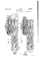
Figure 1 is a longitudinal sectional view through a rock drill showing the novel mechanism with the automatic valve and the piston in normally operative or working condition, 5 this view being a bit diagrammatic in character in illustrating various of the passageways in the same longitudinal plane.
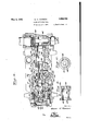
Figure 2 is a similar view showing the mechanism with the automatic valve stopped,
ZU the piston held at the front end of its stroke,
25 with the passageways in their normal relation and showing the apparatus as normally operative.
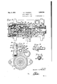
Figure. 4 is a. horizontal sectional view on the line 4 4 of Figure 3.
the automatic valve and showing it being held against movement.
Figure 6 is a cross sectional view on the line 6 6 of Figure 3.
f3 Figure 4' is a side elevation of the fluid operated controlling valve.
Figure S is an end elevation of the same. Figure 9 is a longitudinal sectional view of the cage for the fluid operated valve. Figure is an end elevation thereof. The general structure of the tool and its automatic distributing valve is the same as that disclosed in the application of Edward l F. Terry, Jr.. Ser. No. 167,764, Patent 1574, 302, August 26.v 1930.
A cylinder is illustrated, containing a piston chamber 5, in which a. reciprocatory piston 6 operates, this piston having a hammer extension 7 on one side of the cylinder 4, and preferably integral therewith is lo- Figure 5 is a detail sectional View through cated avalve lcasing 8 having spaced head chambers 9 and 10 connected by a reduced bore 11. i
The outer end of the head chamber 9 is provided with an annular vchannel 12 that communicates with the rear end of the piston chamber 5, through a straight short passageway Or port 13. The inner end of the head chamber 9 has communication with an intermediate portion of the piston chamber by a straight port 14. Between the ports 13 and 14, the head chamber 9 has an internal channel 15, from which opens an exhaust outlet 16 to atmosphere. The head chamber 10 is` somewhat longer than the head chamber 9 and of smaller diameter. It is provided at its front end with an annular channel 17 that communicates by means of a short port 18 `with the front end of the piston chamber 5 in advance of the piston 6. The rear end of the head chamber 10 has a straight port connection 19 with an intermediate portion of the piston chamber 5 in advance of the port 14. Between the ports 18 and 19 there is formed in the head chamber 10 an annular channel 20, with which an exhaust port 21 communicates, said exhaust port being between the ports 18 and 19. Between the ports 19 and 21 there is formed in the head chamber 10 an annular channel 22, from which leads an exhaust outlet 23 opening to atmosphere.
A reciprocatory valve is located in the valve casing 8. and preferably consists of two sections. This valve has terminal heads 24 and 25 that reciprocate in the respective head chambers 9 and 10. The head 24 therefore has a greater diameter than the head 25. Projecting from each head are reduced shank extensions 26 and 27 that operate in the bore 11 and abut against each other. The heads are hollow and are open-ended, and the shank 26-27 is provided with a bore 28 communicating with the hollow heads. As a consequence it will be evident that the head 24 has a peripheral end pressure surface 29 and an inset pressure surface section 30. The end of the head 24 is preferably provided with an inwardly extending annular fia-nge 31, the inner surface 32 of which obviously equalizes the pressure on an equivalent portion of the surface 30. The inner end face 33 of t-he head 24 constitutes a pressure surface opposed to the pressure surfaces 29 and 30.
The head 25 similarly has an annular end pressure surface section 34 and an inset pressure surface 35. It is provided with an opposing pressure surface 36. Said head furthermore has an annular channel 37 forming a flange 38.
Extending into the outer ends of thehead chambers 9 and 10 are plugs 39 and 40, against which the end faces-29 and 34 of the valve heads are respectively adapted to abut. The plug 39 is hollow and forms a supply port 41 leading from a throttle valve casing 42, in which is a suitable rotatable throttle valve 43.
The structure constitutes a differential valve, and its operation is substantially as follows. Referring first to Figure 2, the'piston is at the forward end of its stroke, and the valve has been shifted to a forward position. As a consequence it will be evident that the motive fluid entering through the port 41 of the plug 39 will pass behind the piston as the same returns from the end of its cushioned stroke, and drives said piston forwardly. During this forward drive the motive fluid in advance of the piston can exhaust freely through the ports 19 and 21, and by way of the head chamber 10 to the exhaust outlet 23. This is due to the fact that when the front end of the valve is abutted against the plug 40, the flange 38 is in an intermediate position with respect to the. channel 22, vso that both ports 19 and 21 are open to the exhaust outlet 23. During this stroke, the valve is held in its forward position by pressure against the rear end surfaces 29 and 30, which surfaces minus the surface 32, are suflicient to overcome the pressure against the opposite face 35 of the head 25, material pressure against the surface 34 being cut 0E by the Contact of said surface against the end of the plug 40. The valve therefore remains in its forward position until the rear end of the piston 6 uncovers the port 14. Then this occurs, additional pressure is brought against the surface 33 and the area of this surface plus the area of the surface 35 is suflicient to overcome the pressure against the surfaces 29 and 30, so that the valve is shifted to the position shown in Figure 1. When this occurs, the exhaust ports 19 and 21 are not only cut oft' by the piston 6, but the exhaust port 19 is cut off from the exhaust outlet 23 by the flange 38, while the exhaust port 21 is cut off by the end wall of the channel 37. The rearward movement of the valve, however, opens port 14 in rear of the piston to the exhaust outlet 16, as shown. Therefore motive fluid passing through the valve and entering through the port 18 will drive the piston 6 rearwardly, while the exhaust can take place freely through the port 14, head chamber 9 and outlet 16. During this movement the valve will be held in its rearward position by reason of the fluid acting against the surfaces 34 and 35, the combined areas thereof being greater than the area of the surface 39 minus the opposing surface 32. As soon as the front end of the piston uncovers the port 19, then motive fluid in the front end of the and this steel is provided with the usual lonil gitudinal bore 46. The piston 6 and hammer extension 7 are provided with a longitudinal bore 47 that allows air'or other motive fluid to pass from the rear end of the piston chamber 5 through the piston and hammer extension and enter the bore 46 when the piston moves forwardly under the influence of the motive fluid behind it. As a consequence this fluid will ordinarily blow out the cuttings from the bottom of the' hole being drilled. *l
This action is, however, intermittent because it is only when thefluid is behind the piston that part will escape into the bore 46 of the drill steel. 0n the retrograde movement of the piston the air, as already explained, escapes through the exhaust ports 14-16. It sometimes happens that the amount of air thus delivered to the bore of the drill steel is not suliicient to clear out the hole, and the object of the present invention is to provide '-fi means for directing a continuous supply of air at line pressure to the bore 46 of the drill steel 44. So far as above described the mechanism is' the same as that disclosed in the Terry, Jr. application, Serial No. 167,764
above mentioned.
To secure the additional result, the following mechanism is employed. rThe plug 40 is tubular in form, and constitutes a piston chamber 48 that opens into the head 7*- chamber 10 by reason of an opening 49 formed in the inner end of said plug 49. A reciprocatory piston 50 is mounted in the piston chamber 48, and has an inwardly extending stem 51 constituting a plunger' valve or plug that is adapted to enter the passageway 28 when the piston is moved to the inner end of the chamber 48. This piston and plug 51 thus constitute a fluid actuated valve for the purposes hereinafter explained. movement of the piston is limited by a stop stem 52 carried thereby and arranged to abut against the outer end wall of the piston chainber 48. The inner end of the piston chamber The outer @'35 48 is open to atmospherethrough a plurality f -l of ports 53 that open into an annular groove 54 having communication with outlet ports 55 in the valve casing 8.
The exhaust port 23 for the front end of the main piston chamber 5 passes through a valve casing 56 formed on one side of the main casing 8. In said valve casing 56 is a rotary valve 57 having a passageway 58 cut in one side. The valve is provided with a suitable handle 59, by which it can be turned either to a position to close the exhaust port 23, as shown in Figures 2 and 5, or to an open position to allow the free exhaust of the air in front of the piston 6 to atmosphere. A bypass passageway 60 leads from the exhaust conducting groove 22, with which the exhaust port 23 communicates, to an annular groove 6l formed on the exterior of the plug 40 and this groove 6l is in communication with the rear end of the piston chamber 48 by means of ports 62.
Extending from the rear end of the chamber 9 is a passageway 63 and extending from the rear end ofthe chamber l0 is a passageway 64, the two meeting at the valve 57. In said valve is a passageway which when the valve is in open position as shown in Figure l affords communication between the passageways 63-64 and atmosphere and when the valve 57 is in closed position as illustrated in Figure 2, establishes communication between said passageway 63-64 and the passageway 60. rl`he plug 5l has a reduced portion 66 which as shown in'Figure 5 is adapted to 1nass through the end wall of the chamber 48 and the face of the piston 50 has grooves 67 that communicate with the groove formed by said reduced portion.
New referring to Figures l, 3 and 4, it will be noted that when the valve 57 is in its open position and the exhaust port 23 from the front end of the piston opens to atmosphere and merely under the control of the automatic distributing valve 24-25, the piston will be reciprocated as originally explained an d as fully disclosed in the aforesaid Terry, Jr. application, Serial No. 167 ,764 because the fluid actuated valve 5l will be in its withdrawn or inoperative position due to the pressure of the actuating fluid against the inner end of the valve plug 5l. If it is desired, however, to stop the operation of the piston and deliver a constant supply of cleansing fluid to the bore 46 of the drill steel 44, the operator has only to move the valve 57 to a position to close the exhaust port 28. lVhen this occurs the fluid that would otherwise go to atmosphere from the front end of the piston, new operates through the by-pass passageway 60, groove 6l, and port 62 against the outer end of the piston 50, moving the plug 5l inwardly or to the position shown in lFigures 2 and 5. This cuts ofi1 the supply of fluid to the front end of the piston and the automatic distributing valve stops in the position shown in said Figures 2 and 5. The result is that the motive fluid continues to enter, forcing said piston to the front end of its stroke, so that the front end of the hammer extension 7 is firmly seated against the rear end of the drill steel 44 and the motive fluid under full line pressure in the rear end of the piston chamber behind the piston continues, thus maintaining a tiOht joint and producing a constant stream of cleansing fluid through the bore 47 into the bore 46 and thus to the bottom of the hole being drilled. As soon as the exhaust controlling valve 57 is reopened the parts will assume their normal action.
Then the valve 57 is closed the port 65 is cut off from atmosphere but serves to carry live air to the rear of the piston 50, thus insuring the positive action and holding the plug 5l. When the valve 57 is open and the passageways 63 and 64 are thus open to atmosphere any air that may otherwise be trapped in front of the flange 38 or behind the head 24 can escape.V
From the foregoing, it is thought that the construction, operation and many advantages of the herein described invention will be apparent to those skilled in the art, without further description, and it will be understood that various changes in the size, shape, proportion and minor details of construction may be resorted to without departing from the spirit or sacrificing any of the advantages of the invention.
Vhat I claim, is:
l. In a tool of the character set forth, the
combination with a cylinder member and a piston operating therein, of means for snpplying motive fluid to the tool, an automotic valve for distributing the motive fluid to the piston to actuate it, means for permitting the exhaust to atmosphere of the fluid. from the piston, fluid actuated means in addition to the automatic distributing valve for cuting off the supply of motive fluid from the distributing valve to one end of the piston, and means for closing the exhaust to atmosphere and directing said exhaust to said fluid actuated means to move it to its operative position. f
2. In a tool of the character set forth, the combination with a cylinder member and a piston operating therein, of means for supplying motive fluid to the tool, an automatic valve for distributing the motive fluid to the piston to actuate it and including a passageway to one end of the piston, a fluid actuated valve for closing said passageway, means for permitting the exhaust from the same end of the piston, a valve for closing the exhaust permitting means and a by-passagew'ay for directing the exhaust when so interrupted to pass to and operate the fluid actuated valve.
3. In a tool of the character set forth, the combination with a cylinder member having a piston chamber and a piston operating therein, of means for supplying motive fluid to the tool, an automatic valve for distributing the motive fluid to the ends of the piston chamber to operate the piston, means for permitting the exhaust from the front end of the piston to atmosphere, means for cutting ofi' the escape of exhaust to atmosphere, a fluid operated device for cutting off the supply of motive fluid from the automatic distributing valve to the front end of the piston chamber, and means for causing the exhaust when cut ofl`1 from atmosphere to operate the said means for cutting off said supply.
il. In a tool c-f the character set forth, the combination with a cylinder member having a piston chamber and a piston operating therein, of means for supplying motive fluid to the tool, an automatic valve for distributing the motive fluid to the ends of the piston chamber to operate the piston, means for permitting the exhaust from the front end of the piston to atmosphere, a valve for closing the exhaust, a fluid operated valve for preventing the supply of motive fluid from the automatic distributing valve to the front end of the piston, and a passageway for directing the exhaust fluid to the fluid operated valve when the exhaust to atmosphere is closed.
5. In a tool of the character set forth, the combination with a cylinder member having a piston chamber and a piston operating in the chamber, an automatic valve for distributing the motive fluid to the piston chamber on opposite sides of the piston to actuate the latter, said valve having a passageway therethrough for delivering motive fluid to one end of the piston, and means for closing said passageway to prevent the delivery of such fluid to stop the valve and piston.
6. In a. tool of the character' set forth, the combination with a cylinder member having a piston chamber and a piston operating in the chamber, an automatic valve for distributing the motive fluid to the piston chamber on opposite sides of the piston to actuate the latter, said valve having a passageway therethrough for delivering motive fluid to the front end of the piston, and means for closing said passageway to prevent the delivery of such fluid to stop the valve and stop the piston at the front end of its stroke.
7. In a tool of the character set forth, the combination with a cylinder member having a piston chamber and a piston operating in the chamber, an automatic valve for distributing the motive fluid to the piston chamber on opposite sides of the piston to actuate the latter, said valve having a passageway therethrough for delivering motive fluid to the front end of the piston, a fluid actuated valve for closing said passageway in the automatic valve, to thereby stop the piston at the front end of its stroke, and means for directing fluid to the fluid' actuated valve to move it.
8. In a tool of the character set forth, the
combination with a cylinder member and a piston operating therein, of means for supplying motive fluid to the tool, an automatic valve for distributing the motive fluid to the piston to actuate it and including a passageway to one end of the piston, means for permitting the exhaust from the same end of the piston, and valve mechanism for closing said passageway and also closing the said exhaust, said valve mechanism also having a supplemental port open to atmosphere to relieve pressure against surfaces of the valve.
9. In a tool of the character set forth, the combination with a cylinder member and' a piston operating therein, of means for supplying motive fluid to the tool, an automatic valve for distributing the motive fluid to the piston to actuate it and including a passageway to one end of the piston, a fluid actuated valve for closing said passageway, means for permitting the exhaust from the same end of the piston, a valve for closing the exhaust permitting means, a by-passageway for directing fluid from one end of the piston to the fluid actuated valve,
and a port in the exhaust closing valve movable to and from a position to communicate with the by-passageway.
l0. In a tool of the character set forth, the
combination with a cylinder member and a 9 piston operating therein, of means for supplying motive fluid to the tool, an automatic valve for distributing the motive fluid to the piston to actuate it and including a passageway to one end of the piston, a fluid actuated valve for closing said passageway, means for permitting the exhaust from the same end of the piston, a valve for closing the exhaust permitting means, a by-passageway for directing fluid from one end of the piston to the fluid actuated valve, and passageways leading from surfaces of the automatic distributing valve to the exhaust closing valve, said exhaust closing valve having a port that is movable to positions to establish communication between said passageways and atmosphere and between said passageways and the by-passageway.
11. In a tool of the character set forth, the combination with a cylinder member and a piston operating therein, of means for supplying motive fluid to the tool, an automatic valve for distributing the motive fluid to the piston to actuate it and including a passageway to one end of the piston, a fluid actuated valve for closing said passageway, means for permitting the exhaust from both ends of the piston, a valve for closing the exhaust permitting means, a by-passageway for directing the exhaust when so interrupted to pass to and operate the fluid actuated valve, and a .second by-passageway leading from the rear end of the piston to admit motive fluid to the fluid actuated valve for insuring its positive operation.
rie
12. In a tool of the character set forth, the combination with a cylinder member and a piston operating therein, of means for supplying motive Huid t the tool, an automatic valve for distributing the motive Huid to the piston to actuate it and including a passageway to one end of the piston, a Huid actuated valve for closing said passageway, means for permitting the exhaust from both ends of the piston, a valve for closing the exhaust permitting means, and a plurality of by-passageways for directing the exhaust and live air from opposite sides of the piston to the fluid actuated valve t0 move it to an active position.
I3. In a tool of the character set forth, the combination with a cylinder member and a piston operating therein, 0f means for supplying motive fluid to the tool, an automatic valve for distributing the motive fluid to the piston to actuate it and including a passageway to one end of the piston, a fluid actuated valve for closing said passageway, means for permitting the exhaust from both ends of the piston, a valve for closing the exhaust permitting means, and a plurality of by-passageways controlled by said exhaust valve for directing both the exhaust and live air from either side of the piston to the iuidy actuated valve to move it to an operative position.
In testimony whereof, I afx my signature.
GUSTAV C. PEARSON.
Priority Applications (1)
| Application Number | Priority Date | Filing Date | Title |
|---|---|---|---|
| US266794A US1856784A (en) | 1928-04-02 | 1928-04-02 | Fluid operated tool |
Applications Claiming Priority (1)
| Application Number | Priority Date | Filing Date | Title |
|---|---|---|---|
| US266794A US1856784A (en) | 1928-04-02 | 1928-04-02 | Fluid operated tool |
Publications (1)
| Publication Number | Publication Date |
|---|---|
| US1856784A true US1856784A (en) | 1932-05-03 |
Family
ID=23016019
Family Applications (1)
| Application Number | Title | Priority Date | Filing Date |
|---|---|---|---|
| US266794A Expired - Lifetime US1856784A (en) | 1928-04-02 | 1928-04-02 | Fluid operated tool |
Country Status (1)
| Country | Link |
|---|---|
| US (1) | US1856784A (en) |
-
1928
- 1928-04-02 US US266794A patent/US1856784A/en not_active Expired - Lifetime
Similar Documents
| Publication | Publication Date | Title |
|---|---|---|
| US5115875A (en) | Hammer drills for making boreholes | |
| US2937619A (en) | Hole cleaning device | |
| US3225841A (en) | Drilling apparatus | |
| US3059619A (en) | Rock drill | |
| US1856784A (en) | Fluid operated tool | |
| US1802987A (en) | Rock drill | |
| US2205736A (en) | Percussive tool | |
| US1293081A (en) | Drill-tool. | |
| US1982656A (en) | Drilling machine | |
| US1880337A (en) | Pressure fluid operated implement | |
| US2058425A (en) | Fluid operated tool | |
| US2001718A (en) | Rock drilling motor | |
| US1384641A (en) | Blowing device for percussive tools | |
| US1942730A (en) | Rock drill | |
| US1361431A (en) | Valve for pneumatic percussive tools | |
| US1581668A (en) | Rock drill | |
| US1594217A (en) | Blowing device | |
| US1929457A (en) | Rock drill | |
| US1737456A (en) | Pressure-fluid motor | |
| US1663403A (en) | Drilling machine | |
| US1965264A (en) | Valve mechanism for rock drills | |
| US1929458A (en) | Drilling mechanism | |
| US1350342A (en) | Valve for percussive tools | |
| US1546100A (en) | Rock drill | |
| US1703229A (en) | Drilling mechanism |