US1856777A - Eccentric for shaking mechanism - Google Patents
Eccentric for shaking mechanism Download PDFInfo
- Publication number
- US1856777A US1856777A US528559A US52855931A US1856777A US 1856777 A US1856777 A US 1856777A US 528559 A US528559 A US 528559A US 52855931 A US52855931 A US 52855931A US 1856777 A US1856777 A US 1856777A
- Authority
- US
- United States
- Prior art keywords
- eccentric
- bushing
- drive shaft
- sleeve
- shaking
- Prior art date
- Legal status (The legal status is an assumption and is not a legal conclusion. Google has not performed a legal analysis and makes no representation as to the accuracy of the status listed.)
- Expired - Lifetime
Links
Images
Classifications
-
- D—TEXTILES; PAPER
- D21—PAPER-MAKING; PRODUCTION OF CELLULOSE
- D21F—PAPER-MAKING MACHINES; METHODS OF PRODUCING PAPER THEREON
- D21F1/00—Wet end of machines for making continuous webs of paper
- D21F1/18—Shaking apparatus for wire-cloths and associated parts
Definitions
- This invention relates to an adjustable eccentric device and more particularly to an eccentric for a shaking mechanism.
- a specific use for my invention is in machinery for making paper.
- screened pulp of constant consistency is allowed to flow onto a traveling horizontal wire screen n commonly referred to as the wire, which is in the form of an endless belt. 7
- the water in the pulp drains through the wire and this drainage may be assisted by suction boxes applied under the wire at certain points.
- pulp fibers must be thoroughly criss-crossed and interwoven on the wire while they are being formed into the paper film or web.
- a shaking or sifting motion is. applied, i go to the wire through shake rails.
- the present invention comprises a device which is easily adjusted so that the amplitude of shake may be varied from zero up to any given maximum throw depending upon the limits of the device. It should be understood, however, that my eccentric mechanism, while designed primarily to impart a shaking motion to the shake rails of a Fourdrinier paper machine, is also adapted to impart a shaking motion to any device or machine.
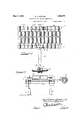
- Figure 1 is a fragmentary top plan view of the Fourdrinier table structure with a shake rail coupled to the eccentric mechanism of my invention.
- Figure 2 is a broken end elevational view of the same.
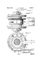
- Figure 3 is an enlarged top plan view of the eccentric mechanism.
- Figure 4 is a sectional View of the eccentric mechanism taken substantially along line IVIV of Figure 3, with parts in elevation.
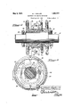
- Figure 5 is a sectional view taken substan tially along line VV of Figure 4.
- Figure 6 is a sectional view taken along line VIVI of Figure 4, with parts broken away.
- the numeral 1 indicates a pair of shake rails upon which are mounted tube rolls 2 secured to the rails through ltrunnions 3 by means of bracket bearings 4.
- the rails 1 are mounted upon spring members 5 which in turn are mounted upon asub frame 6.
- the pair of shake rails 1 are rigidly connected to each other by means of an underslung beam 7 ( Figure 2).
- the purpose of the rigid connection of the two rails is to cause synchronous shaking of both rails.
- Numeral 8 represents a drive shaft upon which is mounted the eccentric device 9.
- the eccentric arm 10 is rigidly secured through a connectinglink 11 to the rear shake 1.
- Eccentric arm 10 imparts a reciprocating motion through the connecting link 11 to beam 7 which is rigidly secured to both shake rails.
- the shake rails I mounted upon the spring members 5 are caused to vibrate and the rollers mounted upon the shake rails are thus also given an oscillatory movement.
- the paper web that is being formed on the wire 12 (Fig. 2) passing over the tube rolls receives the vibratory motion and the fibers are caused to criss-cross and become bonded or matted together.
- the eccentr'c device 9 is shown in detail in Figures 8 to 6 inclusive.
- Said eccentric device 9 comprises a split tapered sleeve 21 positioned around the eccentric portion 20 of the drive shaft and is keyed to the shaft by means of a key 22 (Figs. 5 and 6) so as to prevent relative rotation of the sleeve around the shaft.
- the sleeve is split through its entire length (Fig. 5) to allow for expansion and contraction of the eccentric portion 20 of shaft 8.
- the sleeve is held in fixed horizontal position by means of collars 23. These collars are rigidly attachable to said drive shaft 8 by means of set screws 24.
- the outer surface of the tapered sleeve is provided with screw threads on both ends thereof, and hand wheels 25 and 26 are screwed onto the tapered sleeve.
- Numeral 27 represents an eccentric cam bushing positioned around the middle portion of the tapered sleeve 21.
- a hand wheel 28 is rigidly attached to one side of the eccentric cam bushing 27 by means of screws 39 (Fig. 5).
- the outer surface of the cam bushing 27 is grooved and provided with a bearing surface 29. If desired, a race of ball or roller bearings may be used as the bearing surface.
- Straps 30 and 31 are positioned around the bearing surface 29 ofthe cam bushing 27 by means of bolts 32. Strap 31 is equipped with a flanged portion 10. Said flanged'portion 10 is fastened to the connecting link -1 for connection with the rear shake rail of the table structure. The strap 31 is fitted with an oil cup 33 to oil the bearing surface 29.
- the tapered sleeve 21 is threaded so that the hand wheel 26 is forced against the cam bushing 27 in the same direction of rotation assumed by the drive shaft 8.
- the hand wheel 26 will be forced against the bushing 27 by turning the wheel counterclockwise.
- the hand wheel 26 should be so threaded as to be locked against the eccentric cam bushing by turning it clockwise.
- the position of the eccentric cam bushing 27 ( Figure 4') is set so that the eccentric shaft 8 will have no eccentric throw, due to the fact that the thickest portion in section of the cam bushing is diametrically opposite the highest point of eccentricity of the drive shaft, thereby neutralizing anythrow of this eccentric shaft, the distance from the center line of the shaft to any point on the outside diameter of the cam bushing 27 then beingequal. If the eccentric cam bushing-27 be-moved in its circumferential position relative tothe eccentric shaft 8, the distance from the center line of the shaftto the outside diameter of the bushing will vary according to the position assumed, within the limits of the chosen eccentricity.
- An eccentric device for shaking machines comprising an eccentric drive shaft, a split tapered sleeve secured to said drive shaft, an eccentric-bushing on said sleevehaving a bearing surface, straps positioned around said bearing surface, said bushing being adjustable on said tapered: sleeve to vary the eccentric throw ofthe straps from zero to the maximum throw of the: eccentric drive shaft and eccentric bushing.
- An eccentric device comprising an cecentric drive shaft, a tapered sleeve on the eccentric portionof said driveshaft', means to prevent relative rotation between said sleeve and said drive shaft, means to secure said sleeve against relative axial movement on said drive shaft, an eccentric bushing on said sleeve and means to adjust said bushing on said sleeve to vary the eccentric throw of the device.
- an eccentric drive shaft In an eccentric device, an eccentric drive shaft, an eccentric bushing positioned around said eccentric drive shaft and means to adjust said bushing on said drive shaft to vary the eccentric throw of the device.
- an eccentric device In an eccentric device, an eccentric drive shaft, a tapered sleeve secured thereon, an eccentric bushing adjustable on said sleeve, means for locking said bushing in adjusted position and means associated with said bushing to transmit a shaking movement to an object to be vibrated.
- An eccentric device comprising an eccentric drive shaft, a split tapered sleeve threaded on both ends of its outer surface keyed to said shaft, rigidly attachable collars on said drive shaft positioned at each end of the tapered sleeve to secure said sleeve axially on said drive shaft, an eccentric bushing positioned on the middle portion of said sleeve and having a grooved portion on its outer surface, straps positioned around said grooved portion, bearing means interposed between said bushing and said strap, a flange portion on one of said straps to provide attachment to a shaking mechanism, means attached to said eccentric bushing to adjust the position of the bushing on said sleeve, and locking means screwed on said tapered sleeve to lock sald eccentric bushing in adjusted position.
- a drive shaft an eccentric portion on said drive shaft, an eccentric bushing positioned around said eccentric portion, means for adjusting said bushing relative to said eccentric portion, means for locking said bushing in adjusted position, and means associated with said bushing to transmit a shaking movement to an object to be vibrated.
- an eccentric drive shaft a tapered sleeve secured thereon, an eccentric bushing adjustable axially and circumferentially on said sleeve, means threaded on said sleeve for locking said bushing in adjusted position and straps positioned around i the outer surface of said bushing to transmit a shaking movement to an object to be vibrated.
- an eccentric drive shaft eccentric means adjustable on said eccentric shaft, means to lock said eccentric means in adjusted position and means associated with said eccentric means to transmit a shaking movement to an object to be vily connected with said forming part
- said eccentric device comprising an eccentric drive shaft and eccentric means axially and circumferentially adjustable on said shaft to transmit the desired shaking motion to the forming part.
- an adjustable eccentric device directly and rigidly connected with said rails comprising an eccentric drive shaft, a tapered sleeve secured there-on, an eccentric bushing adjustable on said sleeve, means for locking said bushing in adjusted position and means associated with said bushing to transmit the desired shake to the shake rails.
Landscapes
- Paper (AREA)
Description
y 3, 1932- v M. J. MOLLEN 1,856,777
ECCENTRIC FOR SHAKING MECH NISM Filed April 8, 1931 3 Sheets-Sheet 14:1
7 4 1 I 1 REF-E O i O a rl 1 1 l I Wariz'rz JW alZem Mayv 3, 1932. M. J. MOLLEN ECCENTRIQFOR SHAKING MECHANISM 3 Sheets-Sheet 2 Filed April 8, 1931 I'YYQWZEF" cZWZaZZem May 3, 1932. M. J. MOLLEN ECCENTRIC FOR SHAKING MECHANISM Filed April 8, 19551 3 Sheets-Sheet 3" 77ZarZ2'7ZJ77Z0ZZe70.
Patented May 3, 1932 UNITED STATES PATENT OFFICE MARTIN J. MOLLEN, PORT EDWARDS, WISCONSIN, ASSIGNOR TO NEKOOSA-EDWARDS PAPER COMPANY, OF PORT EDWARDS, WISCONSIN, A CORPORATION OF WISCONSIN EC'CENTRIC FOR SHAKING- MECHANISM Application filed April 8,
This invention relates to an adjustable eccentric device and more particularly to an eccentric for a shaking mechanism.
A specific use for my invention is in machinery for making paper.
' As is well known in the manufacture of paper on a F ourdrinier machine, screened pulp of constant consistency is allowed to flow onto a traveling horizontal wire screen n commonly referred to as the wire, which is in the form of an endless belt. 7 The water in the pulp drains through the wire and this drainage may be assisted by suction boxes applied under the wire at certain points. The
pulp fibers must be thoroughly criss-crossed and interwoven on the wire while they are being formed into the paper film or web. To assist in or cause the interweaving of the pulp fibers a shaking or sifting motion is. applied, i go to the wire through shake rails.
In an average Fourdrinierrtype machine, only a comparatively small section is alloted to the entire shake mechanism, and with the machine running at a high speed it is evident :5 that only a very small interval of time is allowed for interlocking and criss-crossing the fibers of the pulp in forming the paper.
It follows that an efficient shaking or sifting motion must be applied to the shake'rails to 3 properly cause a thorough criss-crossing of the pulp fibers.
Since the kind of pulp used and the speed of the machine are factors which are necessarily variable, means must be provided for varying the frequency and amplitude of the shaking movement applied to'the wire. The present invention comprises a device which is easily adjusted so that the amplitude of shake may be varied from zero up to any given maximum throw depending upon the limits of the device. It should be understood, however, that my eccentric mechanism, while designed primarily to impart a shaking motion to the shake rails of a Fourdrinier paper machine, is also adapted to impart a shaking motion to any device or machine.
It is, therefore, an object of this invention to provide an eccentric device that is readily adjustable to produce any amplitude of shake varying from zero to that caused by the maxi- 1931. Serial No. 528,559.
This invention (in a preferred form) is illustrated in the drawings and hereinafter more fully described.
On thedrawings:
Figure 1 is a fragmentary top plan view of the Fourdrinier table structure with a shake rail coupled to the eccentric mechanism of my invention.
Figure 2 is a broken end elevational view of the same.
Figure 3 is an enlarged top plan view of the eccentric mechanism.
Figure 4 is a sectional View of the eccentric mechanism taken substantially along line IVIV of Figure 3, with parts in elevation.
Figure 5 is a sectional view taken substan tially along line VV of Figure 4.
Figure 6 is a sectional view taken along line VIVI of Figure 4, with parts broken away. I
As shown on the drawings: 7
In Figures 1 and 2, the numeral 1 indicates a pair of shake rails upon which are mounted tube rolls 2 secured to the rails through ltrunnions 3 by means of bracket bearings 4. The rails 1 are mounted upon spring members 5 which in turn are mounted upon asub frame 6. The pair of shake rails 1 are rigidly connected to each other by means of an underslung beam 7 (Figure 2). The purpose of the rigid connection of the two rails, of course, is to cause synchronous shaking of both rails.
The paper web that is being formed on the wire 12 (Fig. 2) passing over the tube rolls receives the vibratory motion and the fibers are caused to criss-cross and become bonded or matted together.
The eccentr'c device 9 is shown in detail in Figures 8 to 6 inclusive. Said eccentric device 9 comprises a split tapered sleeve 21 positioned around the eccentric portion 20 of the drive shaft and is keyed to the shaft by means of a key 22 (Figs. 5 and 6) so as to prevent relative rotation of the sleeve around the shaft. The sleeve is split through its entire length (Fig. 5) to allow for expansion and contraction of the eccentric portion 20 of shaft 8. The sleeve is held in fixed horizontal position by means of collars 23. These collars are rigidly attachable to said drive shaft 8 by means of set screws 24. The outer surface of the tapered sleeve is provided with screw threads on both ends thereof, and hand wheels 25 and 26 are screwed onto the tapered sleeve. r
The outer surface of the cam bushing 27 is grooved and provided with a bearing surface 29. If desired, a race of ball or roller bearings may be used as the bearing surface. Straps 30 and 31 are positioned around the bearing surface 29 ofthe cam bushing 27 by means of bolts 32. Strap 31 is equipped with a flanged portion 10. Said flanged'portion 10 is fastened to the connecting link -1 for connection with the rear shake rail of the table structure. The strap 31 is fitted with an oil cup 33 to oil the bearing surface 29.
As it is essential that hand wheel 26 stay locked against the eccentric cam bushing 27 when the device is in operation, the tapered sleeve 21 is threaded so that the hand wheel 26 is forced against the cam bushing 27 in the same direction of rotation assumed by the drive shaft 8. Thus, if the operator stands facing the hand wheel 26 and the direction of rotation of the drive shaft 8 is counterclockwise, hand wheel 26 will be forced against the bushing 27 by turning the wheel counterclockwise. If, however, the direction of rotation of the drive shaft is clockwise, the hand wheel 26 should be so threaded as to be locked against the eccentric cam bushing by turning it clockwise.-
The eccentric device described above is thus adjustable as follows:
Assuming the direction of rotation of the drive shaft to be clockwise, hand wheel 26 is turned counterclockwise thereby making a, clearance between the hub face ofthis hand wheel and the eccentric cam bushing 27. Handwheel25 is turned to force the eccentric bushing 27 to slide along the tapered portion of the sleeve 21 towards the narrow end thereof, thereby causing the cam bushing 27 to be loosened from the sleeve. Adjusting wheel 28 which is secured to the eccentric cam bushing 27- may now be readily turned to any position around the tapered sleeve 21 to establish the desired stroke of eccentricity. The position of the eccentric cam bushing 27 (Figure 4') is set so that the eccentric shaft 8 will have no eccentric throw, due to the fact that the thickest portion in section of the cam bushing is diametrically opposite the highest point of eccentricity of the drive shaft, thereby neutralizing anythrow of this eccentric shaft, the distance from the center line of the shaft to any point on the outside diameter of the cam bushing 27 then beingequal. If the eccentric cam bushing-27 be-moved in its circumferential position relative tothe eccentric shaft 8, the distance from the center line of the shaftto the outside diameter of the bushing will vary according to the position assumed, within the limits of the chosen eccentricity.
' After thestroke is adjusted to the desired point, the eccentric cam-bushing 27 isforced back on the tapered sleeve 21by turning hand wheel 25 so as to allow clearance between its hub andthe adjusting wheel 28. Hand wheel26 is then turned in a clockwise direction until the cam bushing is-again forced tightly on the tapered sleeve 21.
The misalignment ofeccentricstraps 3'0 and 31 caused by loosening the eccentric-cam bushing. 27 on the tapered sleeve 21' during adjustment of the eccentric throw of the mechanism is permitted by the flexibility of the connecting link 11 (Fig. 1) secured to the serrated portion 35 of the eccentric arm 10 on the strap 31- (Fig. 6).
lVhile I: have indicated the use of my eccentric device in connection with Fourdrinier shake rails, it is obvious that this mechanism may be utilized on any machine that requires shaking, such as, for example, paper and pulp screens, chip screens, ore screens, and the like. The scope of my invention is, therefore, general in its application and is not limited to paper machine use.
I claim as my invention:
1. An eccentric device for shaking machines comprising an eccentric drive shaft, a split tapered sleeve secured to said drive shaft, an eccentric-bushing on said sleevehaving a bearing surface, straps positioned around said bearing surface, said bushing being adjustable on said tapered: sleeve to vary the eccentric throw ofthe straps from zero to the maximum throw of the: eccentric drive shaft and eccentric bushing.
2. An eccentric device comprising an cecentric drive shaft,a tapered sleeve on the eccentric portionof said driveshaft', means to prevent relative rotation between said sleeve and said drive shaft, means to secure said sleeve against relative axial movement on said drive shaft, an eccentric bushing on said sleeve and means to adjust said bushing on said sleeve to vary the eccentric throw of the device.
3. In an eccentric device, an eccentric drive shaft, an eccentric bushing positioned around said eccentric drive shaft and means to adjust said bushing on said drive shaft to vary the eccentric throw of the device.
4:- In an eccentric device, an eccentric drive shaft, a tapered sleeve secured thereon, an eccentric bushing adjustable on said sleeve, means for locking said bushing in adjusted position and means associated with said bushing to transmit a shaking movement to an object to be vibrated.
5. An eccentric device comprising an eccentric drive shaft, a split tapered sleeve threaded on both ends of its outer surface keyed to said shaft, rigidly attachable collars on said drive shaft positioned at each end of the tapered sleeve to secure said sleeve axially on said drive shaft, an eccentric bushing positioned on the middle portion of said sleeve and having a grooved portion on its outer surface, straps positioned around said grooved portion, bearing means interposed between said bushing and said strap, a flange portion on one of said straps to provide attachment to a shaking mechanism, means attached to said eccentric bushing to adjust the position of the bushing on said sleeve, and locking means screwed on said tapered sleeve to lock sald eccentric bushing in adjusted position.
6. In an eccentric device, a drive shaft, an eccentric portion on said drive shaft, an eccentric bushing positioned around said eccentric portion, means for adjusting said bushing relative to said eccentric portion, means for locking said bushing in adjusted position, and means associated with said bushing to transmit a shaking movement to an object to be vibrated.
7. In an eccentric device, an eccentric drive shaft, a tapered sleeve secured thereon, an eccentric bushing adjustable axially and circumferentially on said sleeve, means threaded on said sleeve for locking said bushing in adjusted position and straps positioned around i the outer surface of said bushing to transmit a shaking movement to an object to be vibrated.
8. In an eccentric device, an eccentric drive shaft, eccentric means adjustable on said eccentric shaft, means to lock said eccentric means in adjusted position and means associated with said eccentric means to transmit a shaking movement to an object to be vily connected with said forming part, said eccentric device comprising an eccentric drive shaft and eccentric means axially and circumferentially adjustable on said shaft to transmit the desired shaking motion to the forming part.
10. In a Fourdrinier paper machine including shake rails, an adjustable eccentric device directly and rigidly connected with said rails comprising an eccentric drive shaft, a tapered sleeve secured there-on, an eccentric bushing adjustable on said sleeve, means for locking said bushing in adjusted position and means associated with said bushing to transmit the desired shake to the shake rails.
In testimony whereof I have hereunto subscribed my name at Port Edwards, Wood County, Wisconsin.
MARTIN J. MOLLEN.
Priority Applications (1)
| Application Number | Priority Date | Filing Date | Title |
|---|---|---|---|
| US528559A US1856777A (en) | 1931-04-08 | 1931-04-08 | Eccentric for shaking mechanism |
Applications Claiming Priority (1)
| Application Number | Priority Date | Filing Date | Title |
|---|---|---|---|
| US528559A US1856777A (en) | 1931-04-08 | 1931-04-08 | Eccentric for shaking mechanism |
Publications (1)
| Publication Number | Publication Date |
|---|---|
| US1856777A true US1856777A (en) | 1932-05-03 |
Family
ID=24106182
Family Applications (1)
| Application Number | Title | Priority Date | Filing Date |
|---|---|---|---|
| US528559A Expired - Lifetime US1856777A (en) | 1931-04-08 | 1931-04-08 | Eccentric for shaking mechanism |
Country Status (1)
| Country | Link |
|---|---|
| US (1) | US1856777A (en) |
Cited By (2)
| Publication number | Priority date | Publication date | Assignee | Title |
|---|---|---|---|---|
| US4137159A (en) * | 1977-04-30 | 1979-01-30 | Vernon D. Beehler | Apparatus and method for deliquifying material |
| CN102787527A (en) * | 2012-07-10 | 2012-11-21 | 安吉美伦纸业设备有限公司 | Breast roll shaking box |
-
1931
- 1931-04-08 US US528559A patent/US1856777A/en not_active Expired - Lifetime
Cited By (3)
| Publication number | Priority date | Publication date | Assignee | Title |
|---|---|---|---|---|
| US4137159A (en) * | 1977-04-30 | 1979-01-30 | Vernon D. Beehler | Apparatus and method for deliquifying material |
| CN102787527A (en) * | 2012-07-10 | 2012-11-21 | 安吉美伦纸业设备有限公司 | Breast roll shaking box |
| CN102787527B (en) * | 2012-07-10 | 2014-11-05 | 安吉美伦纸业设备有限公司 | Breast roll shaking box |
Similar Documents
| Publication | Publication Date | Title |
|---|---|---|
| US2445175A (en) | Variable throw vibratory head for screens, conveyers, and the like | |
| US1856777A (en) | Eccentric for shaking mechanism | |
| US2067399A (en) | Eccentric for operating sliver rubbing devices | |
| US3704631A (en) | Adjustable phase two shaft vibrator | |
| US3703128A (en) | Vibrating roller | |
| US1970620A (en) | Pumping unit | |
| US20190126426A1 (en) | Pressing device for sanding machines | |
| US1734929A (en) | Paper-making machine | |
| US2649811A (en) | Variable-speed drive for fabric take-up roll of warp knitting machines | |
| US1839158A (en) | Paper machine | |
| US2270485A (en) | Printing press | |
| US316938A (en) | Fbank x | |
| US2118975A (en) | Comb box | |
| US1266673A (en) | Paper-making machine. | |
| US2645837A (en) | Felt hardening machine | |
| US1038919A (en) | Construction and means of operation of pulp-straining drums for paper-making machines. | |
| US2729179A (en) | Sewing machine bearing and pitman construction | |
| US1917287A (en) | Paper making machine | |
| US2007289A (en) | Drive for doctor oscillators | |
| US1363015A (en) | Belt-tightener | |
| US1721802A (en) | Vibratory screen | |
| US2116168A (en) | Method of and apparatus for forming a pulp web | |
| US1880689A (en) | Press roll gearing | |
| US1453090A (en) | Paper-making machine | |
| US2616153A (en) | Felt hardening machine |