US1856772A - Cooling system - Google Patents
Cooling system Download PDFInfo
- Publication number
- US1856772A US1856772A US471526A US47152630A US1856772A US 1856772 A US1856772 A US 1856772A US 471526 A US471526 A US 471526A US 47152630 A US47152630 A US 47152630A US 1856772 A US1856772 A US 1856772A
- Authority
- US
- United States
- Prior art keywords
- vehicle
- housings
- exhaust
- radiators
- air
- Prior art date
- Legal status (The legal status is an assumption and is not a legal conclusion. Google has not performed a legal analysis and makes no representation as to the accuracy of the status listed.)
- Expired - Lifetime
Links
- 238000001816 cooling Methods 0.000 title description 9
- 238000010276 construction Methods 0.000 description 5
- 238000005192 partition Methods 0.000 description 5
- 239000007789 gas Substances 0.000 description 3
- 238000002485 combustion reaction Methods 0.000 description 2
- 230000015572 biosynthetic process Effects 0.000 description 1
- 230000008602 contraction Effects 0.000 description 1
- 239000000112 cooling gas Substances 0.000 description 1
- 238000010438 heat treatment Methods 0.000 description 1
- 238000004519 manufacturing process Methods 0.000 description 1
- 239000007787 solid Substances 0.000 description 1
Images
Classifications
-
- F—MECHANICAL ENGINEERING; LIGHTING; HEATING; WEAPONS; BLASTING
- F01—MACHINES OR ENGINES IN GENERAL; ENGINE PLANTS IN GENERAL; STEAM ENGINES
- F01P—COOLING OF MACHINES OR ENGINES IN GENERAL; COOLING OF INTERNAL-COMBUSTION ENGINES
- F01P5/00—Pumping cooling-air or liquid coolants
- F01P5/02—Pumping cooling-air; Arrangements of cooling-air pumps, e.g. fans or blowers
- F01P5/08—Use of engine exhaust gases for pumping cooling-air
Definitions
- the present application is a division of the application of Alfred F. Masury and Charles Froesch, Ser. No. 265,136, filed March 27, 1928, for Cooling system which relates to mountings for cooling systems in the rear end of motor vehicles, the internal combustion engines of which are likewise mounted at the rear.
- the present invention is specifically directed to a vehicle body construction wherein provision is made for mounting the foregoing mechanism suitably, at the same time providing a maximum body space and a rear window through which rear vision is afforded.
- the exhaust from the engines mounted in this manner has been utilized to induce a flow of cooling air through the side radiators by means of Venturi throats formed in the exhaust line.
- This type of construction permits the entire power plant to be mounted as a unit at the rear of the vehicle and enables it to be mounted and dismounted quite readily.
- the present invention includes a ventilating system for the interior of the vehicle which enables air to be drawn in through the radiator and discharged into the interior of the vehicle as warm air or, if desired, causes air from the interior to be sucked out through the radiator and discharged from the exhaust stack.
- the latter path is for summer service while the former serves to supply warm air for heating and ventilating the vehicle in the winter time.
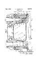
- Figure l is a view in section taken on line.
- Figure 2 is a view in section taken on line 22 of Figure 1, and looking in the directi on of the arrows.
- Figure 3 is a view in section taken on line 3-3 of Figure 1, and looking in the direction of the arrows.
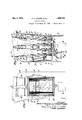
- a designates the body of a vehicle provided with an internal combustion engine I).
- the form shown is of the six cylinder type, the front three cylinders exhausting into the exhaust pipe 6 and the rear three into exhaust pipe 6
- a partition a forms a compartment for the power unit to be described later.
- radiators At either side of the body a, apertures are formed to the rear of which radiators (Z are mounted. Suitable connections (Z accommodate expansion of the radiator and preserve a weather tight joint between it and the side of the vehicle.
- housings e Secured to the rear faces of the radiators are housings e which are provided with horizontal steps 6 to receive exhaust lines formed, in the present instance, as Venturi housings f. These housings communicate with jackets f about the exhaust pipe and manifold and provide a means for ventilating the engine compartment as indicated by the solid arrows about the exhaust manifold in Figure 3.
- the housings 6 also communicate with exhaust stacks g and permit the cooling air to be discharged into the atmosphere after having passed through the radiators.
- a horizontal partition 03 is formed, separating the cooling gases which pass above the partition from those passing below the partition and flowing into the housings 6.
- auxiliary housings being curved to prevent drummin housings e are formed and the air flowing through the upper portion of the radiator and into housings is carried through conduits and motor housing 6 into the interior of the vehicle as indicated in Figure 3.
- a small electric fan is mounted in the motor housing a and creates a flow of air into the vehicle under the proper conditions.
- the housing 6 is sectionalized for convenience in manufacture and assembly, and the stacks are formed with over-hanging lips to -form a storm-tight joint with the roof while permitting expansion and contraction between these members.
- Suitable heat insulationm is provided on the partitions and walls which might readily transmit and radiate heat.
- a very important feature of this invention resides in the formation of the walls as curved surfaces.
- The. housings e, 6 conduits,.radiator mountings, andwindow aperture n are all formed with curved walls, thus preventing body drumming which results from the diaphragm action of plain body walls under vibration.
- This element is quite apparent and its shape such that its walls, being formed with curved surfaces, will not cause drummin.
- a vehicle construction comprising a compartment formed at the rear of the vehicle, side radiators in the compartment, housings communicating with the radiators, exhaust stacks passing through the housings, and means to cause the exhaust gases to draw cooling air through the radiators and into the stacks, the walls of the compartment and The louvres at the left of Figure 1 are 2.
- a vehicle construction comprising a compartment formed at the rear of the vehicle, side radiators in the compartment, housings communicating with the radiators, exhaust stacks passing through the housings, a central opening through the compartment between the housings, and a window in the rear of the opening, the walls of the opening and housings being curved.
Landscapes
- Engineering & Computer Science (AREA)
- Chemical & Material Sciences (AREA)
- Combustion & Propulsion (AREA)
- Mechanical Engineering (AREA)
- General Engineering & Computer Science (AREA)
- Exhaust Silencers (AREA)
Description
May 3, 1932.
A. F. MASURY ET AL 1,356,772
COOLING SYSTEM Original Flled March 27, 1928 2 Sheets-Sheet 1 E *Q INVENTORS flltredlfMaflm'y and Hwsai BY v w, r-LL 7 GW d W I THEIR ATTORNEKS' y 3, 1932- A. F. MASURY ET AL 1,856,772
COOLING SYSTEM Original Filed March 27, 1928 ZSheets-Sheet 2 INVENTORS illfred I Y/(wally and fiat/alive,
12. Q xi-4.. W H516 ATTQRNEYS Patented May 3, 1932 UNITED STATES PATENT @FFKOE ALFRED F. IJIASURY, OF NEW YORK, N. Y., AND CHARLES FROESCH, OF TEANECK, NEW JERSEY, ASSIGNORS TO INTERNATIONAL MOTOR COMPANY OF NEW YORK, N. Y.,
A CORPORATION OF DELAWARE COOLING SYSTEM Original application filed March 27, 1928, Serial No. 265,136. Divided and this application filed July 29, 1930. Serial No. 471,526.
The present application is a division of the application of Alfred F. Masury and Charles Froesch, Ser. No. 265,136, filed March 27, 1928, for Cooling system which relates to mountings for cooling systems in the rear end of motor vehicles, the internal combustion engines of which are likewise mounted at the rear. The present invention is specifically directed to a vehicle body construction wherein provision is made for mounting the foregoing mechanism suitably, at the same time providing a maximum body space and a rear window through which rear vision is afforded. In previous designs, the exhaust from the engines mounted in this manner has been utilized to induce a flow of cooling air through the side radiators by means of Venturi throats formed in the exhaust line. This type of construction permits the entire power plant to be mounted as a unit at the rear of the vehicle and enables it to be mounted and dismounted quite readily.
In addition to the above features, the present invention includes a ventilating system for the interior of the vehicle which enables air to be drawn in through the radiator and discharged into the interior of the vehicle as warm air or, if desired, causes air from the interior to be sucked out through the radiator and discharged from the exhaust stack. The latter path is for summer service while the former serves to supply warm air for heating and ventilating the vehicle in the winter time.
Further objects will appear as the description proceeds and reference will now be had to the accompanying drawings, wherein:
Figure l is a view in section taken on line.
11 of Figure 3, and lookin in the direc tion of the arrows.
Figure 2 is a view in section taken on line 22 of Figure 1, and looking in the directi on of the arrows.
Figure 3 is a view in section taken on line 3-3 of Figure 1, and looking in the direction of the arrows.
Referring to the above figures, a designates the body of a vehicle provided with an internal combustion engine I). The form shown is of the six cylinder type, the front three cylinders exhausting into the exhaust pipe 6 and the rear three into exhaust pipe 6 At the rear of the vehicle, a partition a forms a compartment for the power unit to be described later.
At either side of the body a, apertures are formed to the rear of which radiators (Z are mounted. Suitable connections (Z accommodate expansion of the radiator and preserve a weather tight joint between it and the side of the vehicle.
Secured to the rear faces of the radiators are housings e which are provided with horizontal steps 6 to receive exhaust lines formed, in the present instance, as Venturi housings f. These housings communicate with jackets f about the exhaust pipe and manifold and provide a means for ventilating the engine compartment as indicated by the solid arrows about the exhaust manifold in Figure 3. The housings 6 also communicate with exhaust stacks g and permit the cooling air to be discharged into the atmosphere after having passed through the radiators.
' The exhaust gases pass from the exhaust manifold it through exhaust pipes 72. into Venturi nozzles 2'. Being discharged from these nozzles they flow through successive Venturi throats 7', j and stack 9, he latter being formed with a restricted portion g to cause a further increase in the velocity of the gases as they pass through the stack.
Through the upper portion of the radiators (Z a horizontal partition 03 is formed, separating the cooling gases which pass above the partition from those passing below the partition and flowing into the housings 6. Immediately above the housings e, auxiliary housings being curved to prevent drummin housings e are formed and the air flowing through the upper portion of the radiator and into housings is carried through conduits and motor housing 6 into the interior of the vehicle as indicated in Figure 3. A small electric fan is mounted in the motor housing a and creates a flow of air into the vehicle under the proper conditions. When it is desired to draw air from the interior of the vehicle, pivoted louvres Z are closed, thus preventing air from being drawn from the exterior of the vehicle through the upper portion of the radiator 6. With the louvres closed, the Venturi throat 9' causes air to be drawn through conduit 0 auxiliary housing 6 through the upper portion of the radiator and out through the stack is indicated by dot and. dash arrows tothe left of- Figure 1. shown as closed, which position corresponds tosumm'er operation, while those at the right of Figure 1 are shown as open, corresponding to operating conditions in the winter time. It will be quite apparent that in the summer time the electric fan 70 will not be in operation.
The housing 6 is sectionalized for convenience in manufacture and assembly, and the stacks are formed with over-hanging lips to -form a storm-tight joint with the roof while permitting expansion and contraction between these members. Suitable heat insulationm is provided on the partitions and walls which might readily transmit and radiate heat.
A very important feature of this invention resides in the formation of the walls as curved surfaces. The. housings e, 6 conduits,.radiator mountings, andwindow aperture n are all formed with curved walls, thus preventing body drumming which results from the diaphragm action of plain body walls under vibration. By providing two stacks at either side of the vehicle they may be made small enough to accommodate a Window opening a at the rear of the vehicle and between the stacks. The desirability of this element is quite apparent and its shape such that its walls, being formed with curved surfaces, will not cause drummin The invention has been described in connection with the specific construction shown in the accompanying drawings, but its scope is notto be limited, save as defined in the appended. claims.
We claim as our invention:
1 .A vehicle construction comprising a compartment formed at the rear of the vehicle, side radiators in the compartment, housings communicating with the radiators, exhaust stacks passing through the housings, and means to cause the exhaust gases to draw cooling air through the radiators and into the stacks, the walls of the compartment and The louvres at the left of Figure 1 are 2. A vehicle construction comprising a compartment formed at the rear of the vehicle, side radiators in the compartment, housings communicating with the radiators, exhaust stacks passing through the housings, a central opening through the compartment between the housings, and a window in the rear of the opening, the walls of the opening and housings being curved.
This specification signed.
ALFRED F. MASURY. CHARLES F ROESCH.
tum
Priority Applications (1)
| Application Number | Priority Date | Filing Date | Title |
|---|---|---|---|
| US471526A US1856772A (en) | 1928-03-27 | 1930-07-29 | Cooling system |
Applications Claiming Priority (2)
| Application Number | Priority Date | Filing Date | Title |
|---|---|---|---|
| US265136A US1938846A (en) | 1928-03-27 | 1928-03-27 | Cooling and ventilating system |
| US471526A US1856772A (en) | 1928-03-27 | 1930-07-29 | Cooling system |
Publications (1)
| Publication Number | Publication Date |
|---|---|
| US1856772A true US1856772A (en) | 1932-05-03 |
Family
ID=26951002
Family Applications (1)
| Application Number | Title | Priority Date | Filing Date |
|---|---|---|---|
| US471526A Expired - Lifetime US1856772A (en) | 1928-03-27 | 1930-07-29 | Cooling system |
Country Status (1)
| Country | Link |
|---|---|
| US (1) | US1856772A (en) |
Cited By (5)
| Publication number | Priority date | Publication date | Assignee | Title |
|---|---|---|---|---|
| US2456512A (en) * | 1943-12-31 | 1948-12-14 | Hyster Co | Muffler for internal-combustion engines |
| US4618020A (en) * | 1979-06-06 | 1986-10-21 | Honda Giken Kogyo Kabushiki Kaisha | Motorcycle |
| US5495909A (en) * | 1991-01-03 | 1996-03-05 | Siemens Automotive Limited | Automotive vehicle engine bay ventilation by ducted-fan-operated ejector |
| US20060283647A1 (en) * | 2005-06-15 | 2006-12-21 | Honda Motor Co., Ltd. | Cowling structure of motorcycle |
| US20080251038A1 (en) * | 2004-04-06 | 2008-10-16 | Dr. Ing. H.C.F. Porsche Aktiengesellschaft | Body and Front Axle Bearing for a Motor Vehicle |
-
1930
- 1930-07-29 US US471526A patent/US1856772A/en not_active Expired - Lifetime
Cited By (7)
| Publication number | Priority date | Publication date | Assignee | Title |
|---|---|---|---|---|
| US2456512A (en) * | 1943-12-31 | 1948-12-14 | Hyster Co | Muffler for internal-combustion engines |
| US4618020A (en) * | 1979-06-06 | 1986-10-21 | Honda Giken Kogyo Kabushiki Kaisha | Motorcycle |
| US5495909A (en) * | 1991-01-03 | 1996-03-05 | Siemens Automotive Limited | Automotive vehicle engine bay ventilation by ducted-fan-operated ejector |
| US20080251038A1 (en) * | 2004-04-06 | 2008-10-16 | Dr. Ing. H.C.F. Porsche Aktiengesellschaft | Body and Front Axle Bearing for a Motor Vehicle |
| US7918297B2 (en) * | 2004-04-06 | 2011-04-05 | Dr. Ing. H.C. F. Porsche Ag | Body and front axle bearing for a motor vehicle |
| US20060283647A1 (en) * | 2005-06-15 | 2006-12-21 | Honda Motor Co., Ltd. | Cowling structure of motorcycle |
| US7370902B2 (en) * | 2005-06-15 | 2008-05-13 | Honda Motor Co., Ltd. | Cowling structure of motorcycle |
Similar Documents
| Publication | Publication Date | Title |
|---|---|---|
| US2242494A (en) | Ventilating and cooling system for motor vehicles | |
| US2391408A (en) | Vehicle heater | |
| US2138001A (en) | Engine and exhaust pipe cooling system | |
| US3908900A (en) | Recirculating automotive heating system | |
| US2250795A (en) | Cooling system for automotive vehicle engines | |
| US1856772A (en) | Cooling system | |
| US2104772A (en) | Storage battery installation | |
| US1598867A (en) | Air-cooling system for engines | |
| US3812906A (en) | Armored vehicles housing a cooled engine | |
| US2158758A (en) | Apparatus for heating motor vehicles | |
| US1938846A (en) | Cooling and ventilating system | |
| US2230580A (en) | Motor car | |
| US2766836A (en) | Air intake and delivery device for the inner compartment of motor vehicle bodies | |
| US3289938A (en) | Air-conditioning of automobile vehicles | |
| US1983723A (en) | Carburetor air intake arrangement | |
| US3583630A (en) | Heating and ventilating installation for motor vehicles | |
| US3327773A (en) | Fresh air heating arrangement for a motor vehicle | |
| US4709855A (en) | Recirculating heating system | |
| US3850229A (en) | Air intake system | |
| US1668490A (en) | Heating apparatus for automotive vehicles | |
| US1833067A (en) | Heating apparatus for automotive vehicles | |
| US1803436A (en) | Combined heater and exhaust manifold | |
| US1317750A (en) | Cobol b | |
| US1294438A (en) | Automobile-heater. | |
| US2068739A (en) | Automobile heater |