US1856768A - Assembling apparatus - Google Patents
Assembling apparatus Download PDFInfo
- Publication number
- US1856768A US1856768A US544638A US54463831A US1856768A US 1856768 A US1856768 A US 1856768A US 544638 A US544638 A US 544638A US 54463831 A US54463831 A US 54463831A US 1856768 A US1856768 A US 1856768A
- Authority
- US
- United States
- Prior art keywords
- assembling
- plate
- rod
- plunger
- assembled
- Prior art date
- Legal status (The legal status is an assumption and is not a legal conclusion. Google has not performed a legal analysis and makes no representation as to the accuracy of the status listed.)
- Expired - Lifetime
Links
- 238000012360 testing method Methods 0.000 description 71
- 238000009877 rendering Methods 0.000 description 37
- 230000008093 supporting effect Effects 0.000 description 26
- 238000012856 packing Methods 0.000 description 5
- 239000012530 fluid Substances 0.000 description 3
- MJBPUQUGJNAPAZ-AWEZNQCLSA-N butin Chemical compound C1([C@@H]2CC(=O)C3=CC=C(C=C3O2)O)=CC=C(O)C(O)=C1 MJBPUQUGJNAPAZ-AWEZNQCLSA-N 0.000 description 2
- 210000004907 gland Anatomy 0.000 description 2
- 238000003466 welding Methods 0.000 description 2
- MJBPUQUGJNAPAZ-UHFFFAOYSA-N Butine Natural products O1C2=CC(O)=CC=C2C(=O)CC1C1=CC=C(O)C(O)=C1 MJBPUQUGJNAPAZ-UHFFFAOYSA-N 0.000 description 1
- 238000010276 construction Methods 0.000 description 1
- 230000003111 delayed effect Effects 0.000 description 1
- 230000001788 irregular Effects 0.000 description 1
- 239000000463 material Substances 0.000 description 1
- 229920000136 polysorbate Polymers 0.000 description 1
- 230000000284 resting effect Effects 0.000 description 1
- 238000007789 sealing Methods 0.000 description 1
- 239000002699 waste material Substances 0.000 description 1
Images
Classifications
-
- B—PERFORMING OPERATIONS; TRANSPORTING
- B23—MACHINE TOOLS; METAL-WORKING NOT OTHERWISE PROVIDED FOR
- B23P—METAL-WORKING NOT OTHERWISE PROVIDED FOR; COMBINED OPERATIONS; UNIVERSAL MACHINE TOOLS
- B23P19/00—Machines for simply fitting together or separating metal parts or objects, or metal and non-metal parts, whether or not involving some deformation; Tools or devices therefor so far as not provided for in other classes
- B23P19/02—Machines for simply fitting together or separating metal parts or objects, or metal and non-metal parts, whether or not involving some deformation; Tools or devices therefor so far as not provided for in other classes for connecting objects by press fit or for detaching same
-
- Y—GENERAL TAGGING OF NEW TECHNOLOGICAL DEVELOPMENTS; GENERAL TAGGING OF CROSS-SECTIONAL TECHNOLOGIES SPANNING OVER SEVERAL SECTIONS OF THE IPC; TECHNICAL SUBJECTS COVERED BY FORMER USPC CROSS-REFERENCE ART COLLECTIONS [XRACs] AND DIGESTS
- Y10—TECHNICAL SUBJECTS COVERED BY FORMER USPC
- Y10T—TECHNICAL SUBJECTS COVERED BY FORMER US CLASSIFICATION
- Y10T29/00—Metal working
- Y10T29/53—Means to assemble or disassemble
- Y10T29/53796—Puller or pusher means, contained force multiplying operator
- Y10T29/5383—Puller or pusher means, contained force multiplying operator having fluid operator
Definitions
- rlhis invention relates to machines for assembling a rod membei with a plate member by press-fitting both members together and also for subsequently testing the tightness of fit between these two members.
- One ofthe objects of this invention is to provide a machine of this character which shall be simple in construction, easy to operate, reliable in operation and eliminate waste of time.
- the present invention provides a machine having a workliolder for supporting both membersv to be assembled and having means for firmly hold- .l ing one of the assembled members while applying a force to the other members tending to disassemble the press-fitted members, an assembling device eiecting relative movement between both members, a testing device which applies a force to one of the assembled members tending to disassemble them, and a contact means which. renders the disassembling device inoperative when the assembling device is operati-ve and vice versa.
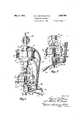
- Fig. 1 is a perspective view of the machine embodying the present invention.
- FIG. 2 is a fragmentary perspective view -.f' of the machine similar to Fig. 1 but showing a different position of certain parts of the machine.
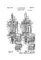
- Fig. 3 is a cross sectional view of the machine showing the work and test plunger in idle position, the two sectional views of the valve are taken on the line 36E-3a and 236-3?) of Fi 6.
- section Sli-3?) being shown under- .eatli section '3a- 3a in a diagrammatic maner for better illustration of the communicaof the different valve chambers.
- i l is a cross sectional View of the machine similar to Fig. 3, however, showing the work plunger at the end of the work stroke, the valve is shown in the same manner as in so Fig. 3 only in diii'erent position.
- Fig. 5 is a cross sectional view of the machine similar torFigs. 3 and 4C, however,.show. ing the work plunger in such position as to allow the testl plunger to act upon the assem- 'led work, the valve is shown in the same manner' and corresponding in position with that of Fig. 3.
- Fig. 6 is a sectional View of the valve taken on the lines 6 6 of Fig. 5.
- Fig. 7 is a sectional view of the valve taken on the lines 7 7 ⁇ ofk F 5.
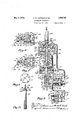
- Fig. 8 shows a distributor shaft and a weight plate in. disassembled position, in which position these parts will be inserted in thek work holder.
- Fig. 9 is a plan. View of the members to be assembled.
- a table 10 of suit- ,A able design supports a bracket 11 through in ⁇ terposed wooden blocks 12; a plurality of bolts 13 projecting through lugs 141 of the bracket 11. secures the latter tothe table 10 by nuts: 14a.
- Guide pieces 15 and 16 overlap A the ends of a base plate 17 and allow. for limited vertical movement of a pad 18.
- A. bolt 19 projects through each of the guide pieces 15 and 16 and isthreaded into the bracket 11, thus securing the guide pieces 15 and 16 and the base plate 17 to said bracket 11 and also confining the pad 1Sv to its limited vertical movement..
- A. plurality of locating pins 25 let in the top of the work holder 18 are received by slots 26 of a weight plate 27 to be assembled, thus locating the weight plate 27 with respect to the pad 18.
- the pad 18 also provides a recess 28 adapted to receive the collar '29 of a distributor shaft 30 and locates the latter with respect to the weight plate 27 A narrow slot. 31 immediately beneath the recess 28 provides sufiicient space for the distributor shaft 30 and a shoulder 32 formed b v the step from the recess 28 to the narrow slot 31 supports the collar 29 and thereby the distributor shaft 30.
- a reduced portion 34 of a member 35 which is welded to the base plate 17 as at 36.
- This member 35 provides a slot 37 which is in longitudinal alignment with recess 28 of the work holder 18 and adapted to confine the shaft 30 to horizontal movement in one direction only, to wit from where the shaft and the plate to be assembled are inserted in the pad 18 and the member ⁇ 35.
- the member 35 has to its lower end secured by welding as at 38 or otherwise a cylindrical body 39 having a central aperture 40 with internal square threads 41 or any other type of threads suitable for the usage in this particular combination.
- the internally threaded aperture is adapted to receive the correspondingly threaded portion 42 of a plug 43 which provides a threaded longitudinal center passage 44 adapted to receive a threaded supporting stem 45, adjustable within the plug 43 in any desired posiiion and secured in such adjusted position thereto by a locknut 46.
- the stem 45 projects through a hole 47 in the bottom 48 of the cylindrical body 39 and into the slot 37 of the member 35 and is adapted to prevent longitudinal movement of the distributor shaft 30 when the press fitting operation takes yplace as will be explained later.
- a handle 49 secured to the plug 43 in any suitable manner allows for manual longitudinal shifting of the plug 43 and thereby engagement or disengagement of the supporting stem 45 with the distributor shaft 30.
- the bracket 11 also provides an extending platform 50 whichterminates into a boss 51.
- a flange 52 integral and concentric with the boss 51 is adapted to support a cylinder 53 which is secured thereto by bolts 54.
- a head 55 is firmly pressed against the top 56 ofthe cylinder wall 57 by bolts 58 which project through. holes 59 in the head 55 and are thread-edly received by a flange 60 of the cylinder .E3-thus sealingl the cylinder.
- the cylinder 53 as well as the head 55 provide bores 61 and 62, respectively, adapted to guide a Work plunger 63.
- a central bore 64 being in axial alignment with the bores 61 and 62 and extending through the flange 52 and the boss 51 is adapted to slidably support the work plunger 63, the comparatively long bore 64 also taking the place of an otherwise necessary packing gland, bv suiiiciently sealing the bottom side of the cylinder 53.
- rIhe head 55 provides a packing chamber 65 for receiving a packing gland 66 while a stuffing box 67 enters with its cylindrical portion 68 the packing chamber 65 and retains the packing 66 in tight engagement with the work plunger 63 thus establishing concealment of the head side of the cylinder 53.
- a plurality of bolts 69 which project through holes 7 0 of the stuffing box 67 are threadedly received by the head 55' and thus secure the stuffing box 67 to the head 55.
- the boss 51 of the bracket 11 thrcadedly receives a guide pin 71 (see Fi 1 or adapted to project into a longitudinal groove 72 of the work plunger 63, to prevent rotation of the same about its own axis.
- the work plunger 63 comprises an enlarged portion 73, part of which is threaded as at 74 and adapted to journal three layers of any suitable piston material which together form a piston 74a.
- a collar 7 5 of the work plunger' 63 supports the piston 74a while a nut 75a, received by the threaded part 74 of the enlarged portion 73 secures the piston 74a to the collar 75 of the work plunger 63.
- the assembling plunger 63 also carries at its lower end a press head 76 which is threaded upon the plunger 63 as at 77.
- This press head provides a slot 78 which is in longitudinal alignment with the recess 28 of the pad 18 and adapted to provide room for the diametrically smallest portion 79 of the distributor shaft 30, while the press head 76 itself engages thetop of the weight plate 27 during the press fitting operation as clearly shown in Fig. 1.
- Compressed fluid in the present instance compressed air has been selected as means for actuating the assemblingv plunger 63. such air being conducted from any suitable supply (not shown). Means for controlling the air pressure iuid will be described later.
- the assembling plunger 63 is hollow and slidably supports another plunger 80.
- the test plunger hereinafter called the test plunger, which provides an intermediate collar 81 resting against the upper end of the assemblingl plunger 63.
- a spiral spring 82 surrounding the test plunger and bearing against the collar 81 also bears against the bottom of a spring cage 83 which isthreaded upon the assembling plunger 63 as at 84. thus yieldingly maintaining the collar 81 of the test plunger 80 in engagement with the assembling plunger 63.
- the test plunger 8O will bear against the top of the distributor shaft 3.6 when the press head 76 is approaching the weight plate 27. Wvhile so doing. the test plunger 80 merely presses the distributor shaft 30 against its supporting stem 45.
- the test plunger 80 merely presses the distributor shaft 30 against its supporting stem 45.
- the test plunger 80 continues for some definite time to, press against the top of the dis-tributar shaft 3() and this time the test plunger will tend to separate the just assembled members.
- the distributor shaft support-ing stem 45 has been withdrawn as will be explained later.
- the pad 18 will follow the withdrawing stem 45 until stopped by the base plate 17, in which position the pad 18 merely supports the weight plate 27 but not the distributor shaft 30.
- the entire predetermined pressure of the test plunger is now imparted from the distributor shaft 30 through the press fitted joint between both members to the weight plate 27, firmly supported by the pad 18 which in turn is firmly supported by the base plate 17 as mentioned.
- the predetermined amount of pressure constitutes a sufficient safety factor of the tightness of fit between the assembled members, and if such tightness of lit is inadequate, the applied pressure of the test plunger will disassemble the members.
- An L-shaped plate 85 comprising legs 86 and 87, is secured to the cylindrical body 39 by welding as at 88 or otherwise, and leg 87 thereof is adapted to support a valve body 89 having open passages 90, 91, 92 and a plugged passage 93, the passages 90, 91 and 92 respectively matching with holes 93, 94 and 95 of the leg 87 of the plate 80.
- Air may pass from a chamber 96 to a chamber 97 through a hole 98 in a valve seat 99 closed by a valve 100 mounted on a stem 101 and normally maintained in closed position by a spiral spring 102, and then to a chamber 103 through a passage 104 (see Fig. 7 connecting the chambers 97 and 103. JAir may also pass from the chamber 96 to a.
- chamber 105 through an irregular passage indicated by line 106, connecting both chambers, then to a chamber 107 through hole 108 in a valve seat 109 closed by a valve 110 mounted on a sleeve 111 and normally maintained in closed position by a spiral spring 112, and may finally pass to a chamber 113 through a passage 114 connecting the chambers 107 and 113 as clearly shown in Fig. 6.
- Air may pass from the chamber 103 to a chamber 115 through a hole 116 in a valve seat 117 closed by a valve 118 mounted on a stem 119 and normally maintained in closed position by a spiral spring 120, then may pass through a passage 121 and finally escape through a vent 122 to the atmosphere as clearly shown in Fig. 7.
- Air may pass from the chamber 113 to a chamber 123 through a hole 124 in a valve seat 125, closed by a valve 126 mounted o-n a stem 127 and normally maintained in closed position by a spiral spring 128, then may pass from chamber 123 through a passage 129 and finally escape through the vent 122 to the atmosphere as clearly shown in Fig. 6.
- V The lower ends of the valve stems are engageable with a latch lever 130, fulcrumed on a pin 131, carried by brackets 132 extending from the valve body 89.
- An extension 133 of the latch lever 130 is adapted to be engaged by adjusting screws 134 and 135 threadedly received by lingers or lugs 136 and 137, respec- ,7
- Compressed air is now admitted to flow from the supply of compressed air (not shown) through a suitable medium, such as a hose or pipe 138 to the entry passage 90 of the valve body 89, then through its following passages and chambers 96, 99, 98, 97, 104, 103 and 91, and from there through a hose or pipe 139, to the head side of the cylinder 53.
- a suitable medium such as a hose or pipe 138
- the expanding compressed air in the head side of the cylinder 53 pushes the assembling plunger 63 from the position shown in Fig. 3 to that shown in Fig. 4.
- Air will then be admitted to flow from the supply of compressed air through the medium 138 to the entry passage 90 of the valve body 89, then through the Valve body 89 and particularly through the following passages and chambers 96, 106, 105, 109, 108, 107, 114, 113, 92 and finally through the hose or pipe 140, connecting the last said passage 92 with the bottom side of the cyl'- inder 53.
- rPhe expanding air in this part of the cylinder 53 pushes the assembling plunger 63 from the position shown in Fig. 4 to that shown in Fig. 3.
- the machine is shown in a state of rlhe work plunger 63 with the press head 7 6 and also the pad 18 are in an uppermost position, the former due to the pressure of compressed air in the bottomside of the cylinder 53 and the latter' due to the tendencv of the springs 20.
- the operator loosely assembles the weight plate 27 and the distributor shaft 30 in substantially the same manner as shown in Fig.
- Thel rotary motion of the handle 49 also results in a shifting of the latch lever by the adjusting screw 134 carried by the longitudinally extending finger 136 of the plug 43 into such position which allows compressed air from a suitable supply (not shown) to pass through the pipe or hose 138 to the entrance passage 90, then through the passa-ges and chambers of the valve body 83, as earlier explained, then through a pipe or hose 139 to the head side of the cylinder 53 as clearly shown in Fig. 4.
- test plunger 80 will engage the top of the distributor shaft 30 and impart axial pressure to said shaft 30 which, however, is taken up by the supporting stem or stop 45. Air in the bottom side of the cylinder 53 is allowed to esca-pe the advancing plunger in the earlier described manner.
- the ⁇ latter has not yet reached the end of its half stroke, but keeps u on moving and during that time the press head finally engages the weight plate 27 and performs the press fitting operation by forcing the center hole of the weight plate 27 over the l-:nurled portion 19 of the vertically arrested distributor shaft 30 until its collar 29 prevents any further movement of the weight plate 27 as well as of the press head 76, and therefore, of the assembling plunger n also.
- Fig. 5 shows the test plunger acting with its full force upon the distributor shaft 30 and tending to disassenible the work, but the withdrawing work plunger will soon engage the collar 81 of the test plunger 8O and raise the latter out of engagement with the worlr. Since, however, the withdrawal of the plunger is delayed with respect to the withdrawal of the distributor shaft supporting stem due to the slower response of compressed air as means for actuating a plunger compared with the bodily response of the supporting stem 45, such delay must be added to the time which it takes for the assembling plunger to travel through the distance between the collar 8l and the assembling plunger 63 as shown in Fig. 5.
- this invention embodies a machine which not only performs the press iitting operation in a satisfactory and simple manner, but at the same time undertakes to test each and every piece of assembled work by actually dislocating one of the inadequately press iitted members with respect to the other press fitted meinber. rlhe machine of the present invention therefore does the work of an inspector in jpossibly a more eiiicient and satisfactory manner than the inspector would be able to do, and does such testing work during the ordinary time of performing the assembling operation without requiring any skill or additional manipulation of the operator.
- a machine for assembling a. rod with a plate and for testing the tightness of fit between the assembled members comprising in combination, a work holder for supporting both members to be assembled and having means for firmly holding one of the assembled members while applying a force to the other member tending to disasseinble the members, an assembling device effecting relative moven'ent between both members, a testm ing device which applies force to one of the einbled members tending to disassemble them, and a control means which renders the testing device inoperative when the assembling device is operative and vice versa.
- a machine for assembling a rod with a plate and for testing the tightness of lit be tween the assembled members comprising in combination, a work holder for holding one of the members while the other member is moved relative thereto for assembling purposes, said work holder including means for holdin@ one of the members while applying a force to the other member tending to separate the assembled members, a device for applying an assembling force to the movable member, a testing device for applying a force to one of the assembled members tending to separate them, and a control means for rendering tlie assembling device inoperative when the testing device is operative and vice versa.
- a machine for assembling a rod with a plate and for testing the tightness of fit between the assembled members comprising in combination, a work holder including means for holding a rod member while moving the plate member relative thereto for assembling purposesand means for holding the plate member while applying a force to the rod member tending to disassenible the assembled members, a device for applying anassembling force to the plate member, a testing device for applying a predetermined force to the assembled rod member but in a direction relatively opposite to that required for as sembly, and a control means for rendering the testing device inoperative when the assembling device is operative and vice versa.
- a machine for assembling a rod with a plate and for testing the tightness of lit between the assembled members comprising in combination, a work holder including means for holding a rod member while moving the plate member relative thereto for assembling purposes and means for holding the plate member while applying a force to the rod member tending to disasseinble the assembled members, a device for applying an assembling force to the plate member, a testing de vice for applyingapredetermined force to theV assembled rod member but in a direction relatively opposite to that required for assembly,
- A' machine for assembling a rod with a plate and for testing the tightness of lit between the assembled members comprising in combination, a work holder including means for holding a rod while moving the plate relative thereto for assembling purposes and means for holding the plate while applying a force to the rod tending to separate the assembled work, a device for applying an assembling force to the plate, a spring for applying a predetermined testing force to the assembled rod but in a direction relatively opposite to that required for assembly, and a control means for rendering the spring inoperative when the assembling device is operative and vice versa.
- a machine for assembling a rod with a plate and for testing the tightness of lit between the assembled members comprising in combination, a work holder including means ⁇ lor holding the rod and means for holding the plate a device for applying an assembling force to the plate, a spring Jfor applying a predetermined testing force to the assembled rod but in a direction relatively opposite to that required for assembly, and a control means for rendering the spring inoperative and causing the rod to be held by said means of the work holder when the assembling device is operative or for rendering the assemling means inoperative and causingthe plate to be held by the said means of the work holder when the spring isoperative.
- a machine for assembling ⁇ a rod *ith a plate and for testing the assembled members comprising in combination, a work holder ining the plate relative thereto for assembling purposes and means for holding the plate while applying a torce to the rod tending to separate the assembled work, a power oper- -ated assembly plunger for moving the plate,
- testing device which applies a predetermined orce to the assembled rod but in a direction relatively opposite to that required for assembly and a control means for rendering the disassembling device inoperative when the assembly plunger is operative and vice versa.
- a machine for assembling a rod with a plate and for testing the tightness of lit between the assembled members comprising in combination, a work holder including means for holding the rod and means for holding the plate, a power operated assembly plunger Jfor moving the plate, a testing device which applies a predetermined force to the assembled rod but in a direction relatively opposite to that required for assembly, and a control means for ellecting release of the assembling plunger for causing the rod to be held stationary by the said means of the work holder and for rendering the spring inoperative, or for rendering the assembling plunger inoperative and coincidentally therewith causing the plate to be held by the said means of the work holder and rendering the spring operative.
- a machine for assembling a rod with a plate and for testing the tightness of lit between the assembled members comprising in combination, a work holder having a stop for supporting the rod and a pad for supporting the plate, an assembly device for applying an assembling force to the plate, a testing device for applying a predetermined force to the assembled rod but in a direction relatively opposite to that required for assembly, and a control means for rendering the assembling device operative, for causing the stop to support the rod to resist movement of the plate, and for rendering the testing device inoperative, or for rendering the testing device operative, coincidentally therewith causing the pad to support the plate, and for rendering the assembling device inoperative.
- a machine for assembling a rod with a plate and for testing the tightness of fit between the assembled members comprising in combination, a work holder having a stop for supporting the rod and a pad for supporting the plate, a power operated assembling plunger or moving the plate, a testing device for applying a predetermined force to the assembled rod but in a direction relatively opposite to that required for assembly, and a control means for releasing the power operated assembling plunger, for causing the stop to support the rod, and for rendering the testing device inoperative, or for causing the stop to withdraw from the rod, coincidentally therewith rendering the testing device operative and for causing the pad to support the plate.
- a machine for assembling a rod with a plate and Jfor testing the tightness of fit between the assembled members comprising in combination, a work holder having a stop for supporting the rod and a pad for supporting the plate, an assembly device tor applying an assembling force to the plate, a spring for applying a predetermined testing force to the assembled rod but in a direction relatively opposite to that required for assembly, and a control means Jrior rendering the assembling device operative, for causing the stop to support the rod to resist movement of the plate, and for rendering the spring inoperative, or for causing the stop to withdraw from the rod, coincidentally therewith rendering the spring operative, causing the pad of the work holder to hold the plate and rendering the assembling device inoperative.
- a machine for assembling a rod with a plate and for testing thetightness ot lit between the assembled members comprising in combination, a work holder having a stop tor supporting the rod and a pad for supporting the plate, a power operated assembling plunger for moving the plate, a spring ior applying a predetermined testing force to the assembled rod but in a direction relatively opposite to that required for assembly, and a control means for rendering the power operated assembling plunger operative, causing the stop to support the rod to resist movement of the plate and rendering the spring inoperative, or for causing the stop to withdraw from the rod and coincidentally therewith rendering the spring operative, causing the pad of the Work holder to hold the plate stationary and rendering the work plunger inoperative.
- a machine for assembling a rod with a plate and for testing the tightness of fit between the assembled members comprising in combination, a work holder including a pad which is movable with the plate and a stop for supporting the rod, a device tor applying an assemblingl force to the plate, a testing device which applies a predetermined force to the rod but in a direction relatively opposite to that required for assembly and a control means for rendering the assembling device operative, causing the stop ofthe work holt er to support the rod and rendering the testing device inoperative, or for causing the stop to release the rod, coincidentally therewith rendering the testing device operative and causing the pad of the work plunger to hold the plate stationary.
- a machine for assembling a rod with a plate and for testing the tightness of lit between the assembled member comprising in combination, a work holder including a pad which is movable with the plate and a stop for supporting the rod, a power operated assembling plunger for moving the plate, a testing device which applies a predetermined torce to the rod but in a direction relatively opposite to that required for assembly, and a control means for releasing the power operated assembling plunger, causing the stop of the work holder to support the rod, and rendering the testing device inoperative, or for causing the stop to withdraw from the rod and coincidentally therewith rendering the power operated assembling plunger inoperat-ive and causing the pad of the work holder to hold the plate stationary to resist the force of the testing device.
- a machine for assembling a rod with a plate and for testing the tightness of lit between the assembled member comprising A in combination, a work holder including a pad which is movable with the plate and a stop tor supporting the rod, a device for applying an assembling force to the plate, a spring for applying a predetermined testing force to the rod, but in a direction relatively opposite to that required for assembly, and a control means for rendering the assembling device operative, causing the stop of the work holder to support the rod and rendering the spring inoperative, or for causing .the stop to withdraw from the rod and coincidentally therewith rendering the assembling device inoperative, rendering the spring operative, and causing the pad of the work holder to hold the plate stationary.
- a machine for assembling a rod with a plate and for testing the tightness of lit between the assembled members comprising in combination, a work holder including a pad which is movable with the plate and a stop for supporting the rod, a power operated assembling plunger for moving the plate, a spring :tor applying a predetermined testing torce to the rod, butin a direction relatively opposite to that required :tor assembly, and a control means for rendering the assembling plunger operative, causing the stop of the work holder to support .the rod and rendering the spring inoperative, or for causing the stop to withdraw from the rod and coincidentally therewith rendering the assembling plunger inoperative, rendering the spring operative and also causing the pad of the work holder to hold the plate stationary.
- a machine for assembling a rod with a plate and :tor testing the tightness of fit between the assembled members comprising in combination, a work holder including a pad which is movable with the plate and a stop for supporting the rod, a fluid pressure operated assembling plunger for moving the' plate while the rod is held stationary, a valve for controlling the assembling plunger, a spring for applying a predetermined testing force to the rod, but in a direction relatively opposite to that required for assembly, and a control means for shifting the valve in such position which renders the assembling plunger operative, for causing the stop of the work holder to support the rod and :tor Vrendering the spring inoperative, or for causing the stop to withdraw from the rod for causing the pad ot the work holder to hold the plate stationary and for shitting the valve in such position which renders the assembling plunger' inoperative and renders the spring operative.
- a machine for assembling a rod wit-h a plate and for testing the tightness of it between the assembled members comprising in combination, a work holder including a pad which is movable with the plate and a stop for supporting the rod, a fluid pressure operated assembling plunger for moving the plate while the rod is held stationary, a valve for controlling the assembling plunger, a spring for applying a predetermined testing force to the rod, but in a direction relatively opposite to that required for assembly, and a control member shiftable in an inclined plane about an axis parallel to the axis of the rod,
Landscapes
- Engineering & Computer Science (AREA)
- Mechanical Engineering (AREA)
- Testing Of Devices, Machine Parts, Or Other Structures Thereof (AREA)
Description
May 3, 1932- s. NJJoHNscN E1' AL 1,856,768
ASSEMBLING APPARATUS Filed June l5, 1931 3 Sheets-Sheet 2.,
May 3, 1932. s'. N. JOHNSON r-:T AL 1,855,768
.VSSEMBLING APPARATUS 'Filed June 15; 1931 s sheets-sheet s /zg/Z /26//5 45 /5/22 /7 923,35
/4-0 /zv i 0,26 /za /26//5 a9 6795 Z v /0/ 9747096 7l 5MM MM M 90M M M @www4 tio Patented May 3, 1932 essere SGURD N'. JOHNSON ANI) CHARLES E. BIRCH, OF ANDERSON., INDIANA, ASSIGNORS T0 DELCO-BEMY CORPOEATIGN, OF ANDERSON,
WARE
ASSEMBLING Application filed. .Tune 15,
rlhis invention relates to machines for assembling a rod membei with a plate member by press-fitting both members together and also for subsequently testing the tightness of fit between these two members.
One ofthe objects of this invention is to provide a machine of this character which shall be simple in construction, easy to operate, reliable in operation and eliminate waste of time.
In order to accomplish this the present invention provides a machine having a workliolder for supporting both membersv to be assembled and having means for firmly hold- .l ing one of the assembled members while applying a force to the other members tending to disassemble the press-fitted members, an assembling device eiecting relative movement between both members, a testing device which applies a force to one of the assembled members tending to disassemble them, and a contact means which. renders the disassembling device inoperative when the assembling device is operati-ve and vice versa.
Further objects and advantages of the present invention will be apparent from the following description, reference being had to the following drawings wherein a preferred embodiment of one form of the present invention is clearly7 shown.
ln the drawings:
Fig. 1 is a perspective view of the machine embodying the present invention.
2 is a fragmentary perspective view -.f' of the machine similar to Fig. 1 but showing a different position of certain parts of the machine.
Fig. 3 is a cross sectional view of the machine showing the work and test plunger in idle position, the two sectional views of the valve are taken on the line 36E-3a and 236-3?) of Fi 6. section Sli-3?) being shown under- .eatli section '3a- 3a in a diagrammatic maner for better illustration of the communicaof the different valve chambers.
i l is a cross sectional View of the machine similar to Fig. 3, however, showing the work plunger at the end of the work stroke, the valve is shown in the same manner as in so Fig. 3 only in diii'erent position.
INBIANA, A. CORPORATION OF DELA- AEPARAT'US 1,931. Serial. No.V 544,636.
Fig. 5 is a cross sectional view of the machine similar torFigs. 3 and 4C, however,.show. ing the work plunger in such position as to allow the testl plunger to act upon the assem- 'led work, the valve is shown in the same manner' and corresponding in position with that of Fig. 3. A
Fig. 6 is a sectional View of the valve taken on the lines 6 6 of Fig. 5.
Fig. 7 is a sectional view of the valve taken on the lines 7 7` ofk F 5.
Fig. 8 shows a distributor shaft and a weight plate in. disassembled position, in which position these parts will be inserted in thek work holder.
Fig. 9 is a plan. View of the members to be assembled.
Work' holder Referring to the drawings a table 10 of suit- ,A able design supports a bracket 11 through in` terposed wooden blocks 12; a plurality of bolts 13 projecting through lugs 141 of the bracket 11. secures the latter tothe table 10 by nuts: 14a. Guide pieces 15 and 16, overlap A the ends of a base plate 17 and allow. for limited vertical movement of a pad 18. A. bolt 19 projects through each of the guide pieces 15 and 16 and isthreaded into the bracket 11, thus securing the guide pieces 15 and 16 and the base plate 17 to said bracket 11 and also confining the pad 1Sv to its limited vertical movement.. A pair of springs 20, diagonally situated with respect to the bottom of the pad 18 and located within aligned annular recesses 21 and 22 of the base plate 17 and the pad 18". respectively, normally maintain the pad 18 in an uppermost position, while a pair of dowel pins 23, situated equally spaced from the spring and let in the base plate 17. are slidably received by holes 24 of the pad 18 for preventing lateral movement of the same. A. plurality of locating pins 25 let in the top of the work holder 18 are received by slots 26 of a weight plate 27 to be assembled, thus locating the weight plate 27 with respect to the pad 18.
The pad 18 also provides a recess 28 adapted to receive the collar '29 of a distributor shaft 30 and locates the latter with respect to the weight plate 27 A narrow slot. 31 immediately beneath the recess 28 provides sufiicient space for the distributor shaft 30 and a shoulder 32 formed b v the step from the recess 28 to the narrow slot 31 supports the collar 29 and thereby the distributor shaft 30.
Located within a bore 33 of the base plate 17 is a reduced portion 34 of a member 35 which is welded to the base plate 17 as at 36. This member 35 provides a slot 37 which is in longitudinal alignment with recess 28 of the work holder 18 and adapted to confine the shaft 30 to horizontal movement in one direction only, to wit from where the shaft and the plate to be assembled are inserted in the pad 18 and the member` 35.
The member 35 has to its lower end secured by welding as at 38 or otherwise a cylindrical body 39 having a central aperture 40 with internal square threads 41 or any other type of threads suitable for the usage in this particular combination. The internally threaded aperture is adapted to receive the correspondingly threaded portion 42 of a plug 43 which provides a threaded longitudinal center passage 44 adapted to receive a threaded supporting stem 45, adjustable within the plug 43 in any desired posiiion and secured in such adjusted position thereto by a locknut 46. The stem 45 projects through a hole 47 in the bottom 48 of the cylindrical body 39 and into the slot 37 of the member 35 and is adapted to prevent longitudinal movement of the distributor shaft 30 when the press fitting operation takes yplace as will be explained later. A handle 49 secured to the plug 43 in any suitable manner allows for manual longitudinal shifting of the plug 43 and thereby engagement or disengagement of the supporting stem 45 with the distributor shaft 30.
Assembling device The bracket 11 also provides an extending platform 50 whichterminates into a boss 51. A flange 52, integral and concentric with the boss 51 is adapted to support a cylinder 53 which is secured thereto by bolts 54. A head 55 is firmly pressed against the top 56 ofthe cylinder wall 57 by bolts 58 which project through. holes 59 in the head 55 and are thread-edly received by a flange 60 of the cylinder .E3-thus sealingl the cylinder. The cylinder 53 as well as the head 55 provide bores 61 and 62, respectively, adapted to guide a Work plunger 63. .A central bore 64 being in axial alignment with the bores 61 and 62 and extending through the flange 52 and the boss 51 is adapted to slidably support the work plunger 63, the comparatively long bore 64 also taking the place of an otherwise necessary packing gland, bv suiiiciently sealing the bottom side of the cylinder 53. rIhe head 55 provides a packing chamber 65 for receiving a packing gland 66 while a stuffing box 67 enters with its cylindrical portion 68 the packing chamber 65 and retains the packing 66 in tight engagement with the work plunger 63 thus establishing concealment of the head side of the cylinder 53. A plurality of bolts 69 which project through holes 7 0 of the stuffing box 67 are threadedly received by the head 55' and thus secure the stuffing box 67 to the head 55. The boss 51 of the bracket 11 thrcadedly receives a guide pin 71 (see Fi 1 or adapted to project into a longitudinal groove 72 of the work plunger 63, to prevent rotation of the same about its own axis.
|The work plunger 63 comprises an enlarged portion 73, part of which is threaded as at 74 and adapted to journal three layers of any suitable piston material which together form a piston 74a. A collar 7 5 of the work plunger' 63 supports the piston 74a while a nut 75a, received by the threaded part 74 of the enlarged portion 73 secures the piston 74a to the collar 75 of the work plunger 63.
The assembling plunger 63 also carries at its lower end a press head 76 which is threaded upon the plunger 63 as at 77. This press head provides a slot 78 which is in longitudinal alignment with the recess 28 of the pad 18 and adapted to provide room for the diametrically smallest portion 79 of the distributor shaft 30, while the press head 76 itself engages thetop of the weight plate 27 during the press fitting operation as clearly shown in Fig. 1.
Compressed fluid, in the present instance compressed air has been selected as means for actuating the assemblingv plunger 63. such air being conducted from any suitable supply (not shown). Means for controlling the air pressure iuid will be described later.
Testing device The assembling plunger 63 is hollow and slidably supports another plunger 80. hereinafter called the test plunger, which provides an intermediate collar 81 resting against the upper end of the assemblingl plunger 63. A spiral spring 82, surrounding the test plunger and bearing against the collar 81 also bears against the bottom of a spring cage 83 which isthreaded upon the assembling plunger 63 as at 84. thus yieldingly maintaining the collar 81 of the test plunger 80 in engagement with the assembling plunger 63. The test plunger 8O will bear against the top of the distributor shaft 3.6 when the press head 76 is approaching the weight plate 27. Wvhile so doing. the test plunger 80 merely presses the distributor shaft 30 against its supporting stem 45. However. when the press head 7 6 withdraws from the just assembled members. the test plunger 80 continues for some definite time to, press against the top of the dis-tributar shaft 3() and this time the test plunger will tend to separate the just assembled members. since coincidentally with the withdrawal of the assembling plunger 63 the distributor shaft support-ing stem 45 has been withdrawn as will be explained later. The pad 18 will follow the withdrawing stem 45 until stopped by the base plate 17, in which position the pad 18 merely supports the weight plate 27 but not the distributor shaft 30. The entire predetermined pressure of the test plunger is now imparted from the distributor shaft 30 through the press fitted joint between both members to the weight plate 27, firmly supported by the pad 18 which in turn is firmly supported by the base plate 17 as mentioned. The predetermined amount of pressure constitutes a sufficient safety factor of the tightness of fit between the assembled members, and if such tightness of lit is inadequate, the applied pressure of the test plunger will disassemble the members.
Control mechanism An L-shaped plate 85, comprising legs 86 and 87, is secured to the cylindrical body 39 by welding as at 88 or otherwise, and leg 87 thereof is adapted to support a valve body 89 having open passages 90, 91, 92 and a plugged passage 93, the passages 90, 91 and 92 respectively matching with holes 93, 94 and 95 of the leg 87 of the plate 80.
Air may pass from a chamber 96 to a chamber 97 through a hole 98 in a valve seat 99 closed by a valve 100 mounted on a stem 101 and normally maintained in closed position by a spiral spring 102, and then to a chamber 103 through a passage 104 (see Fig. 7 connecting the chambers 97 and 103. JAir may also pass from the chamber 96 to a. chamber 105 through an irregular passage indicated by line 106, connecting both chambers, then to a chamber 107 through hole 108 in a valve seat 109 closed by a valve 110 mounted on a sleeve 111 and normally maintained in closed position by a spiral spring 112, and may finally pass to a chamber 113 through a passage 114 connecting the chambers 107 and 113 as clearly shown in Fig. 6.
Air may pass from the chamber 103 to a chamber 115 through a hole 116 in a valve seat 117 closed by a valve 118 mounted on a stem 119 and normally maintained in closed position by a spiral spring 120, then may pass through a passage 121 and finally escape through a vent 122 to the atmosphere as clearly shown in Fig. 7. Air may pass from the chamber 113 to a chamber 123 through a hole 124 in a valve seat 125, closed by a valve 126 mounted o-n a stem 127 and normally maintained in closed position by a spiral spring 128, then may pass from chamber 123 through a passage 129 and finally escape through the vent 122 to the atmosphere as clearly shown in Fig. 6.
V The lower ends of the valve stems are engageable with a latch lever 130, fulcrumed on a pin 131, carried by brackets 132 extending from the valve body 89. An extension 133 of the latch lever 130 is adapted to be engaged by adjusting screws 134 and 135 threadedly received by lingers or lugs 136 and 137, respec- ,7
tively, which are integral with the plug 43. Therefore, when the handle 49 is shifted from the position shown in Fig. 2 to that shown in Fig. 1, the adjusting screw 134 will shift the latch lever 130 into such position that the valves and 118 will be closed due to the tension of their respective spiral spring while the valves 126 and 100 will be opened by the latch lever 130 against the tension of their respective spiral spring, as clearly shown in Fig. 4. Compressed air is now admitted to flow from the supply of compressed air (not shown) through a suitable medium, such as a hose or pipe 138 to the entry passage 90 of the valve body 89, then through its following passages and chambers 96, 99, 98, 97, 104, 103 and 91, and from there through a hose or pipe 139, to the head side of the cylinder 53. The expanding compressed air in the head side of the cylinder 53 pushes the assembling plunger 63 from the position shown in Fig. 3 to that shown in Fig. 4.
Coincidentally with the movement of the assembling plunger, air in the bottom side of the cylinder 53 must be admitted to escape the advancing plunger 63. Such air passes through a pipe or hose 140, connecting the bottom side of the cylinder 53 with the passage 92 of the valve body 89, then from this passage through its following passages and chambers 113, 125, 124, 123, 129 and out to the atmosphere through the vent 122.
When the handle 49 is shifted from the position shown in Fig. 1 to that shown in Figs. 2, 6 and 7, the adjusting screw 135 will shift the latch lever 130 into such position that the valves 100 and 126 will be closed due to the tension of their respective spiral spring, while the valves 118 and 110 will be opened by the latch lever 130 against the tension of their respective spiral spring as clearly shown in Figs. 3, 6 and 7. Air will then be admitted to flow from the supply of compressed air through the medium 138 to the entry passage 90 of the valve body 89, then through the Valve body 89 and particularly through the following passages and chambers 96, 106, 105, 109, 108, 107, 114, 113, 92 and finally through the hose or pipe 140, connecting the last said passage 92 with the bottom side of the cyl'- inder 53. rPhe expanding air in this part of the cylinder 53 pushes the assembling plunger 63 from the position shown in Fig. 4 to that shown in Fig. 3. Coincidentally with the flowing of compressed air to the bottom side of the cylinder 41 and the movement of the work plunger 49, air from the head side of the cylinder 53 must be admitted to escape the advancing plunger 63 through the pipe or hose 139 then through the valve body 89 and in particular through its following passages and Ico chambers 91, 103,117,11G,'115, 121 and out to the atmosphere through the vent 122.
lt will be readily understood from the description so far that a manual shifting of the handle 49 causes engagement or disengagement of the adjustable distributor shaft supportingstem 45 with or from the distributor shaft 30 and at the same time controls the downward movement, respectively, upward movement of the assembling plunger 63.
Mode of operation The sequence of operations of the present ifsention will be best understood by referringl to Figs. 1 to 5 inclusive.
Referring nist to Fig. 3, the machine is shown in a state of rlhe work plunger 63 with the press head 7 6 and also the pad 18 are in an uppermost position, the former due to the pressure of compressed air in the bottomside of the cylinder 53 and the latter' due to the tendencv of the springs 20. The operator loosely assembles the weight plate 27 and the distributor shaft 30 in substantially the same manner as shown in Fig. 8, and inserts them into the pad 18 andmember 35 in such manner that the slots 26 of the weight plate 27 are received by the locating pins 25 and the collar 29 of the distriautor shaft by t e recess 28 of the work holder pad 13, and tne distril'xuor sh: ft 3() itself confined to the shaft surrounding work holder member 35.
The operator, having done these introducing manipulations now starts the machine by shifting handle 49 from the position as shown in Fig. 2, to that shown in Fig. 1, which rotary motion is imparted to the threaded plug 43 and results in a longitudinal movement of the plug 43 within the cylindrical body 39 and therewith engagement of the adjustable suppoi ing stem th the lower end of the distributor shaft bf).
Thel rotary motion of the handle 49 also results in a shifting of the latch lever by the adjusting screw 134 carried by the longitudinally extending finger 136 of the plug 43 into such position which allows compressed air from a suitable supply (not shown) to pass through the pipe or hose 138 to the entrance passage 90, then through the passa-ges and chambers of the valve body 83, as earlier explained, then through a pipe or hose 139 to the head side of the cylinder 53 as clearly shown in Fig. 4. The admitted compressed air expands and moves the asi plm I i' G3 and therewith the press head 7 6 slowly toward the work, but before the press head 76 engages the top of the weight plate 27, the test plunger 80 will engage the top of the distributor shaft 30 and impart axial pressure to said shaft 30 which, however, is taken up by the supporting stem or stop 45. Air in the bottom side of the cylinder 53 is allowed to esca-pe the advancing plunger in the earlier described manner.
At the time the test plunger 80 engages the distributor shaft 30 and is therefore prevented from further movement with the assembling plunger, the `latter has not yet reached the end of its half stroke, but keeps u on moving and during that time the press head finally engages the weight plate 27 and performs the press fitting operation by forcing the center hole of the weight plate 27 over the l-:nurled portion 19 of the vertically arrested distributor shaft 30 until its collar 29 prevents any further movement of the weight plate 27 as well as of the press head 76, and therefore, of the assembling plunger n also.
The assembling or press fitting operation of the machine is now comuleted and the operator shifts the handle 49 from the position shown in Fig. 1, back to the initial position as shown in Fig. 2. This causes withdrawal of the distributor shaft supporting stem 45 coincidentally with the shifting of the handle 49, as has been adequately explained, and also causes the adjusting screw 135, carried by the longitudinally extending finger 137 of the plug 43 to shift the latch lever 130 from the position shown in F ig. 4 to that shown in Fig. 5 which position allows compressed air from the supply to pass through the medium 138 to the entrance passage 90 of the valve body 89 then through its passages and chambers as earlier explained, and finally through a pipe or hose 140 to the bottom side of the cylinder 53. The admitted compressed air in the bottom side of lthe cylinder 53 expands of the distributor shaft 30 earlier than the assembling plunger, when the latter engages the weight plate 27, during its first half stroke. When therefore assembling plunger starts to withdraw from the assembled work, it has first to take up its extra motion of the first half stroke with respect to the test plunger 80. During that time the spring pressed test plunger 80 will with its entire force press against the top of the t ie distributor shaft 30 which will give way l longitudinally since the distributor shaft supporting stem has been withdrawn and the stronger test plunger actuating spring 82 overcomes the much weaker pad supporting springs 20. the assembled work, continues until the bottom of the movable pad 18 rests against the base plate 17. In this position the lower end of the distributor shaft 30 has not yet reached the withdrawn suprlhis giving away of .111:
porting stem 45 and since the test plunger 80 continues to press aXially with full Vforce against the distributor shaft 30, this full force must be transmitted from the distributor shaft through the just press fitted joint to the weight plate 27 and then to the new firmly supported pad 18. lf the joint is not tight enough, the predetermind force of the test plunger S0 will sepa-rate the distributor shaft 30 and the immovable weight plate 27 and thus enable the operator to easily distinguishfbetween satisfactory and inferior work.
Fig. 5 shows the test plunger acting with its full force upon the distributor shaft 30 and tending to disassenible the work, but the withdrawing work plunger will soon engage the collar 81 of the test plunger 8O and raise the latter out of engagement with the worlr. Since, however, the withdrawal of the plunger is delayed with respect to the withdrawal of the distributor shaft supporting stem due to the slower response of compressed air as means for actuating a plunger compared with the bodily response of the supporting stem 45, such delay must be added to the time which it takes for the assembling plunger to travel through the distance between the collar 8l and the assembling plunger 63 as shown in Fig. 5.
inferior work out of the work holder and ini serts new members to be assembled in the manner described.
From this it may be seen that this invention embodies a machine which not only performs the press iitting operation in a satisfactory and simple manner, but at the same time undertakes to test each and every piece of assembled work by actually dislocating one of the inadequately press iitted members with respect to the other press fitted meinber. rlhe machine of the present invention therefore does the work of an inspector in jpossibly a more eiiicient and satisfactory manner than the inspector would be able to do, and does such testing work during the ordinary time of performing the assembling operation without requiring any skill or additional manipulation of the operator.
lVliile the form of embodiment of the present invention as herein disclosed, constitutes a preferred form, it is to be understood that other forms might be adopted, all coming lwitliin the scope of the claims which follow.
What is claimed is as follows:
1. A machine for assembling a. rod with a plate and for testing the tightness of fit between the assembled members, comprising in combination, a work holder for supporting both members to be assembled and having means for firmly holding one of the assembled members while applying a force to the other member tending to disasseinble the members, an assembling device effecting relative moven'ent between both members, a testm ing device which applies force to one of the einbled members tending to disassemble them, and a control means which renders the testing device inoperative when the assembling device is operative and vice versa.
2. A machine for assembling a rod with a plate and for testing the tightness of lit be tween the assembled members, comprising in combination, a work holder for holding one of the members while the other member is moved relative thereto for assembling purposes, said work holder including means for holdin@ one of the members while applying a force to the other member tending to separate the assembled members, a device for applying an assembling force to the movable member, a testing device for applying a force to one of the assembled members tending to separate them, and a control means for rendering tlie assembling device inoperative when the testing device is operative and vice versa.
3. i machine for assembling a rod with a plate and for testing the tightness of fit between the assembled members, comprising in combination, a work holder including means for holding a rod member while moving the plate member relative thereto for assembling purposesand means for holding the plate member while applying a force to the rod member tending to disassenible the assembled members, a device for applying anassembling force to the plate member, a testing device for applying a predetermined force to the assembled rod member but in a direction relatively opposite to that required for as sembly, and a control means for rendering the testing device inoperative when the assembling device is operative and vice versa.
4. A machine for assembling a rod with a plate and for testing the tightness of lit between the assembled members, comprising in combination, a work holder including means for holding a rod member while moving the plate member relative thereto for assembling purposes and means for holding the plate member while applying a force to the rod member tending to disasseinble the assembled members, a device for applying an assembling force to the plate member, a testing de vice for applyingapredetermined force to theV assembled rod member but in a direction relatively opposite to that required for assembly,
means of the work holder to hold the rod all" cluding means for holding a rod while movmeans or the work holder to hold the plate member and for rendering the testing device operative.
5. A' machine for assembling a rod with a plate and for testing the tightness of lit between the assembled members, comprising in combination, a work holder including means for holding a rod while moving the plate relative thereto for assembling purposes and means for holding the plate while applying a force to the rod tending to separate the assembled work, a device for applying an assembling force to the plate, a spring for applying a predetermined testing force to the assembled rod but in a direction relatively opposite to that required for assembly, and a control means for rendering the spring inoperative when the assembling device is operative and vice versa.
6. A machine for assembling a rod with a plate and for testing the tightness of lit between the assembled members, comprising in combination, a work holder including means `lor holding the rod and means for holding the plate a device for applying an assembling force to the plate, a spring Jfor applying a predetermined testing force to the assembled rod but in a direction relatively opposite to that required for assembly, and a control means for rendering the spring inoperative and causing the rod to be held by said means of the work holder when the assembling device is operative or for rendering the assemling means inoperative and causingthe plate to be held by the said means of the work holder when the spring isoperative.
'7. A machine for assembling` a rod *ith a plate and for testing the assembled members, comprising in combination, a work holder ining the plate relative thereto for assembling purposes and means for holding the plate while applying a torce to the rod tending to separate the assembled work, a power oper- -ated assembly plunger for moving the plate,
a testing device which applies a predetermined orce to the assembled rod but in a direction relatively opposite to that required for assembly and a control means for rendering the disassembling device inoperative when the assembly plunger is operative and vice versa.
8. A machine for assembling a rod with a plate and for testing the tightness of lit between the assembled members, comprising in combination, a work holder including means for holding the rod and means for holding the plate, a power operated assembly plunger Jfor moving the plate, a testing device which applies a predetermined force to the assembled rod but in a direction relatively opposite to that required for assembly, and a control means for ellecting release of the assembling plunger for causing the rod to be held stationary by the said means of the work holder and for rendering the spring inoperative, or for rendering the assembling plunger inoperative and coincidentally therewith causing the plate to be held by the said means of the work holder and rendering the spring operative.
9. A machine for assembling a rod with a plate and for testing the tightness of lit between the assembled members, comprising in combination, a work holder having a stop for supporting the rod and a pad for supporting the plate, an assembly device for applying an assembling force to the plate, a testing device for applying a predetermined force to the assembled rod but in a direction relatively opposite to that required for assembly, and a control means for rendering the assembling device operative, for causing the stop to support the rod to resist movement of the plate, and for rendering the testing device inoperative, or for rendering the testing device operative, coincidentally therewith causing the pad to support the plate, and for rendering the assembling device inoperative.'
10. A machine for assembling a rod with a plate and for testing the tightness of fit between the assembled members, comprising in combination, a work holder having a stop for supporting the rod and a pad for supporting the plate, a power operated assembling plunger or moving the plate, a testing device for applying a predetermined force to the assembled rod but in a direction relatively opposite to that required for assembly, and a control means for releasing the power operated assembling plunger, for causing the stop to support the rod, and for rendering the testing device inoperative, or for causing the stop to withdraw from the rod, coincidentally therewith rendering the testing device operative and for causing the pad to support the plate.
11. A machine for assembling a rod with a plate and Jfor testing the tightness of fit between the assembled members, comprising in combination, a work holder having a stop for supporting the rod and a pad for supporting the plate, an assembly device tor applying an assembling force to the plate, a spring for applying a predetermined testing force to the assembled rod but in a direction relatively opposite to that required for assembly, and a control means Jrior rendering the assembling device operative, for causing the stop to support the rod to resist movement of the plate, and for rendering the spring inoperative, or for causing the stop to withdraw from the rod, coincidentally therewith rendering the spring operative, causing the pad of the work holder to hold the plate and rendering the assembling device inoperative.
12. A machine for assembling a rod with a plate and for testing thetightness ot lit between the assembled members, comprising in combination, a work holder having a stop tor supporting the rod and a pad for supporting the plate, a power operated assembling plunger for moving the plate, a spring ior applying a predetermined testing force to the assembled rod but in a direction relatively opposite to that required for assembly, and a control means for rendering the power operated assembling plunger operative, causing the stop to support the rod to resist movement of the plate and rendering the spring inoperative, or for causing the stop to withdraw from the rod and coincidentally therewith rendering the spring operative, causing the pad of the Work holder to hold the plate stationary and rendering the work plunger inoperative.
13. A machine for assembling a rod with a plate and for testing the tightness of fit between the assembled members, comprising in combination, a work holder including a pad which is movable with the plate and a stop for supporting the rod, a device tor applying an assemblingl force to the plate, a testing device which applies a predetermined force to the rod but in a direction relatively opposite to that required for assembly and a control means for rendering the assembling device operative, causing the stop ofthe work holt er to support the rod and rendering the testing device inoperative, or for causing the stop to release the rod, coincidentally therewith rendering the testing device operative and causing the pad of the work plunger to hold the plate stationary.
14. A machine for assembling a rod with a plate and for testing the tightness of lit between the assembled member, comprising in combination, a work holder including a pad which is movable with the plate and a stop for supporting the rod, a power operated assembling plunger for moving the plate, a testing device which applies a predetermined torce to the rod but in a direction relatively opposite to that required for assembly, and a control means for releasing the power operated assembling plunger, causing the stop of the work holder to support the rod, and rendering the testing device inoperative, or for causing the stop to withdraw from the rod and coincidentally therewith rendering the power operated assembling plunger inoperat-ive and causing the pad of the work holder to hold the plate stationary to resist the force of the testing device.
15. A machine for assembling a rod with a plate and for testing the tightness of lit between the assembled member, comprising A in combination, a work holder including a pad which is movable with the plate and a stop tor supporting the rod, a device for applying an assembling force to the plate, a spring for applying a predetermined testing force to the rod, but in a direction relatively opposite to that required for assembly, and a control means for rendering the assembling device operative, causing the stop of the work holder to support the rod and rendering the spring inoperative, or for causing .the stop to withdraw from the rod and coincidentally therewith rendering the assembling device inoperative, rendering the spring operative, and causing the pad of the work holder to hold the plate stationary.
16. A machine for assembling a rod with a plate and for testing the tightness of lit between the assembled members, comprising in combination, a work holder including a pad which is movable with the plate and a stop for supporting the rod, a power operated assembling plunger for moving the plate, a spring :tor applying a predetermined testing torce to the rod, butin a direction relatively opposite to that required :tor assembly, and a control means for rendering the assembling plunger operative, causing the stop of the work holder to support .the rod and rendering the spring inoperative, or for causing the stop to withdraw from the rod and coincidentally therewith rendering the assembling plunger inoperative, rendering the spring operative and also causing the pad of the work holder to hold the plate stationary. V
17. A machine for assembling a rod with a plate and :tor testing the tightness of fit between the assembled members, comprising in combination, a work holder including a pad which is movable with the plate and a stop for supporting the rod, a fluid pressure operated assembling plunger for moving the' plate while the rod is held stationary, a valve for controlling the assembling plunger, a spring for applying a predetermined testing force to the rod, but in a direction relatively opposite to that required for assembly, and a control means for shifting the valve in such position which renders the assembling plunger operative, for causing the stop of the work holder to support the rod and :tor Vrendering the spring inoperative, or for causing the stop to withdraw from the rod for causing the pad ot the work holder to hold the plate stationary and for shitting the valve in such position which renders the assembling plunger' inoperative and renders the spring operative.
18. A machine for assembling a rod wit-h a plate and for testing the tightness of it between the assembled members, comprising in combination, a work holder including a pad which is movable with the plate and a stop for supporting the rod, a fluid pressure operated assembling plunger for moving the plate while the rod is held stationary, a valve for controlling the assembling plunger, a spring for applying a predetermined testing force to the rod, but in a direction relatively opposite to that required for assembly, and a control member shiftable in an inclined plane about an axis parallel to the axis of the rod,
for usingl one component of the actual movement thereof to shift the valve in such position which renders the assembling plunger operative and the spring inoperative, und for usino' the other com onent of such movement of the member to move the stop into engagement with the rod, or for using the other component of such movement to Withdraw the stop from the rod and for using the one component of such movement to shift the valve into such position which renders the assembling plunger inoperative and coincidentally therewith renders the spring operative and causes the pad of the workholcler to hold the plate stationary.
In testimony whereof We hereto aix our signatures.
SIGURD N. JOHNSON. CHARLES E. BIRCH.
Priority Applications (1)
| Application Number | Priority Date | Filing Date | Title |
|---|---|---|---|
| US544638A US1856768A (en) | 1931-06-15 | 1931-06-15 | Assembling apparatus |
Applications Claiming Priority (1)
| Application Number | Priority Date | Filing Date | Title |
|---|---|---|---|
| US544638A US1856768A (en) | 1931-06-15 | 1931-06-15 | Assembling apparatus |
Publications (1)
| Publication Number | Publication Date |
|---|---|
| US1856768A true US1856768A (en) | 1932-05-03 |
Family
ID=24172984
Family Applications (1)
| Application Number | Title | Priority Date | Filing Date |
|---|---|---|---|
| US544638A Expired - Lifetime US1856768A (en) | 1931-06-15 | 1931-06-15 | Assembling apparatus |
Country Status (1)
| Country | Link |
|---|---|
| US (1) | US1856768A (en) |
Cited By (2)
| Publication number | Priority date | Publication date | Assignee | Title |
|---|---|---|---|---|
| US2664619A (en) * | 1947-04-23 | 1954-01-05 | Gen Motors Corp | Tube flaring and nut assembling machine |
| US3080646A (en) * | 1959-07-03 | 1963-03-12 | Wm W Nugent & Co | Spool assembling machine |
-
1931
- 1931-06-15 US US544638A patent/US1856768A/en not_active Expired - Lifetime
Cited By (2)
| Publication number | Priority date | Publication date | Assignee | Title |
|---|---|---|---|---|
| US2664619A (en) * | 1947-04-23 | 1954-01-05 | Gen Motors Corp | Tube flaring and nut assembling machine |
| US3080646A (en) * | 1959-07-03 | 1963-03-12 | Wm W Nugent & Co | Spool assembling machine |
Similar Documents
| Publication | Publication Date | Title |
|---|---|---|
| US2749867A (en) | Controlled pressure metal forming apparatus | |
| US2502659A (en) | Conveyer chain lubrication | |
| US1856768A (en) | Assembling apparatus | |
| US2893515A (en) | Automatically controlled pneumatically powered lubricator | |
| US1850063A (en) | Hose nozzle for dispensing apparatus | |
| US1899534A (en) | Automobile lift | |
| US3498121A (en) | Test piece centering means for stress-strain machines | |
| GB803020A (en) | Improvements in and relating to a drilling machine | |
| US2682103A (en) | Means for rebushing pistons and the like | |
| US1035828A (en) | Automatic adjustable press. | |
| US2856186A (en) | Open throat air-operated slide feed for power presses and special machines | |
| US2347780A (en) | Apparatus for assembling resilient joints | |
| US2171235A (en) | Automatic fluid connection for toggle actions | |
| US2001711A (en) | Portable testing machine | |
| US1924545A (en) | Drop hammer | |
| US801528A (en) | Well-drilling machine. | |
| US1880627A (en) | Safety device for hydraulic mechanisms | |
| US1589825A (en) | Spark-plug tester | |
| US2268815A (en) | Welding equipment | |
| US2152837A (en) | Prefill valve for hydraulic presses | |
| US2462116A (en) | Leak testing fixture for valves | |
| US1025163A (en) | Testing apparatus. | |
| US2011863A (en) | Valve lash adjusting mechanism | |
| US2507628A (en) | Pneumatic jack | |
| US2253544A (en) | Press fluid control unit |