US1856746A - Carburetor choke control - Google Patents
Carburetor choke control Download PDFInfo
- Publication number
- US1856746A US1856746A US387216A US38721629A US1856746A US 1856746 A US1856746 A US 1856746A US 387216 A US387216 A US 387216A US 38721629 A US38721629 A US 38721629A US 1856746 A US1856746 A US 1856746A
- Authority
- US
- United States
- Prior art keywords
- cylinder
- rod
- valve
- actuator
- head
- Prior art date
- Legal status (The legal status is an assumption and is not a legal conclusion. Google has not performed a legal analysis and makes no representation as to the accuracy of the status listed.)
- Expired - Lifetime
Links
- 230000006835 compression Effects 0.000 description 2
- 238000007906 compression Methods 0.000 description 2
- 239000000446 fuel Substances 0.000 description 2
- 238000002485 combustion reaction Methods 0.000 description 1
- 238000010276 construction Methods 0.000 description 1
- 239000000203 mixture Substances 0.000 description 1
- 238000007789 sealing Methods 0.000 description 1
Images
Classifications
-
- G—PHYSICS
- G05—CONTROLLING; REGULATING
- G05G—CONTROL DEVICES OR SYSTEMS INSOFAR AS CHARACTERISED BY MECHANICAL FEATURES ONLY
- G05G7/00—Manually-actuated control mechanisms provided with one single controlling member co-operating with one single controlled member; Details thereof
- G05G7/14—Manually-actuated control mechanisms provided with one single controlling member co-operating with one single controlled member; Details thereof characterised by means for delaying initiation of, or making more gradual throughout, the movement of the controlled member in response to a given input from the controlling member, e.g. by providing lost motion in the command train
-
- Y—GENERAL TAGGING OF NEW TECHNOLOGICAL DEVELOPMENTS; GENERAL TAGGING OF CROSS-SECTIONAL TECHNOLOGIES SPANNING OVER SEVERAL SECTIONS OF THE IPC; TECHNICAL SUBJECTS COVERED BY FORMER USPC CROSS-REFERENCE ART COLLECTIONS [XRACs] AND DIGESTS
- Y10—TECHNICAL SUBJECTS COVERED BY FORMER USPC
- Y10S—TECHNICAL SUBJECTS COVERED BY FORMER USPC CROSS-REFERENCE ART COLLECTIONS [XRACs] AND DIGESTS
- Y10S261/00—Gas and liquid contact apparatus
- Y10S261/18—Dashpots
-
- Y—GENERAL TAGGING OF NEW TECHNOLOGICAL DEVELOPMENTS; GENERAL TAGGING OF CROSS-SECTIONAL TECHNOLOGIES SPANNING OVER SEVERAL SECTIONS OF THE IPC; TECHNICAL SUBJECTS COVERED BY FORMER USPC CROSS-REFERENCE ART COLLECTIONS [XRACs] AND DIGESTS
- Y10—TECHNICAL SUBJECTS COVERED BY FORMER USPC
- Y10T—TECHNICAL SUBJECTS COVERED BY FORMER US CLASSIFICATION
- Y10T74/00—Machine element or mechanism
- Y10T74/20—Control lever and linkage systems
- Y10T74/20396—Hand operated
- Y10T74/20468—Sliding rod
Definitions
- This invention relates to a control device for the fuel supply apparatus of an internal combustion engine.
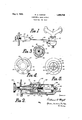
- Fig. 1 is a view showing the choker control device connected with the choker valve of a carburetor.
- Fig. 2 is a longitudinal sectional view taken through the axis of the carburetor choke control device.
- Fig. 3 is a detail sectional view taken along said valve, however, being closed for engine starting purpose whereby, an enriched fuel supply is delivered to the engine.
- the valve 22 has an operating lever 24 on the outside of the carburetor to which one end of a rod 25 is secured.
- the carburetor choke controlling device illustrateddetailedlyin Fig. 2 comprises a bracket -having a plate 31 secured thereto by screws 32. At the end of the bracket 30 opposite the plate 31 an angular portion.33
- L is provided substantially at right angles to e the main body of the bracket.
- a cylindrical portion 34 which slidably supports the cylinder 35.
- said cylinder has a tongue 36 which fits into a groove 37 provided in the inner surface of the cylindrical portion 34.
- a plate 38 is provided having a central opening for receiving a rod 39 which is anchored to the angular portion 33 of the bracket 30 by a nut 40.
- the one end of rod 25 which, as has been described, is connected with the choke valve operating lever 24, extends through an aperture in the bracket portion 33 and is anchored to the end member 38 of the cylinder 35. From this it may be seen that cylinder I 35 is slidably supported at one end by the cylindrical portion 34 of the bracket and at the other end by its end member 38 slidably supported upon the rod 39.
- the rod 39 supports a piston 41 within the cylinder 35, said piston comprising a fibrous cup-shaped washer 42 gripped between members 43 and .44, secured to the rod 39.
- An expansion spring 45 is provided in-- side the fibrous washer 42, said spring urging the washer into sea-ling engagement with the inner wall of the cylinder.
- a cylinder head is secured within the cylinder.
- This head has a central passage 51 longitudinally of the cylinder 35, a portion of said passage being provided with screw threads, another portion is restricted providing the orifice 52.
- This construction provides a compression chamber within the cylinder 35 between the head 50 and the piston 41.
- the plate 31 supported substantially at right angles of the axis of the cylinder 35 has a collar'53 rotatably supported thereby in coaxial alignment with cylinder 35.
- This collar supports an indicating .pointer 54.- adapted to be moved into indicating position relative to the graduated dial 55.
- Collar 53 has a central opening for receiving the square shaft 56, the outer end of which has the actuator 57 securedthereto, the inner end of said square shaft 56 being provided with screw threads of such a nature that the threads are out only in the four corners of the square shaft.
- This shaft 56 threadedly engages the threaded portion of the passage 51 in the cylinder head 50.
- a square shaft and cutting the threads on t e corners of the shaft provides passages 58 between the inner surface of the passage 51 and the outer flat surface of the shaft 56.
- At the inner end of the shaft there is a reduced portion having a pointed end 59 adapted to be moved into various positions relative to the orifice 52 by the rotation of the actuator 57.
- a spring 60 is interposed between the cylinder head 50 and the collar 53, said spring normally urging and tending to maintain the cylinder 35 in the position as shown in Fig. 2, in which position the choke valve 22 of the carburetor is open.
- the device operates as follows. When it is desired to start the engine the operator grasps the actuator 57 and exerts a pull there on which will move the cylinder 35 toward the left as regards Figs. 1 and 2, against the effect of spring 60 whereby, "the rod or link connection 25 will rotate the choker valve operating lever 24 in a counterclockwise direction causing the valve 22 to close the air inlet pipe 23. The engine now receiving a richer mixture will start more readily. After the engine has started the operator releases the hold upon the actuator 57 thereby, permitting spring 60 to return the cylinder 35 to its normal position in which the choke valve 22 is wide open.
- a dash pot control device comprising in combination; a cylinder having a cylinder,
- a dash pot control device comprising in combination; a stationary rod; a cylinder having two apertured, cylinder heads, one of which is slidably supported upon said rod; a piston carried b said rod; a valve in the aperture of the other cylinder head; and an actuator secured to said other cylinder head for moving said cylinder relative to the piston and rod, said actuator being movable relative to the cylinder head to adjust the valve for varying the operation of the device.
- a dash pot control device comprising in combination; a stationar rod; a cylinder having two apertured, cylinder heads, one of which is slidably supported upon said rod; a piston carried by said rod; a restriction in the aperture of the other cylinder head providing an orifice; and an actuator secured to said other cylinder head for moving the cylinder relative to the piston, said actuator providing a valve pin, adjustable by the rotation of the actuator relative to the cylinder head for varying the size of the orifice therein.
- a dash pot control device comprising in
Landscapes
- Physics & Mathematics (AREA)
- General Physics & Mathematics (AREA)
- Engineering & Computer Science (AREA)
- Automation & Control Theory (AREA)
- Means For Warming Up And Starting Carburetors (AREA)
Description
May 3, 1932.
w. A. CHRYSTI.
CARBUHETOR CHOKE CONTROL Filed Aug. 20, 1929 Patented May 3, 1932 UNITED STATES PATENT OFFICE WILLIAM A. OHRYS'I', OF DAYTON, OHIO, ASSIGNOR TO' DELCO PRODUCTS CORPORATION, OF DAYTON, OHIO, A CORPORATION OF DELAWARE CARBURE'IOR CHOKE CONTROL Application filed August 20, 1929. Serial No. 387,216.
This invention relates to a control device for the fuel supply apparatus of an internal combustion engine.
It is among the objects of the present invention to provide a device by which the choker valve of a carburetor may be closed for engine starting purposes, said device havin a retarded movement for opening said oker valve.
Further objects and advantages of the present invention will be'apparent from the following description, reference being had to the accompanying drawings wherein a preferred embodiment of one form of the present invention is clearly shown.
In the drawings: 4
Fig. 1 is a view showing the choker control device connected with the choker valve of a carburetor.
Fig. 2 is a longitudinal sectional view taken through the axis of the carburetor choke control device.
Fig. 3 is a detail sectional view taken along said valve, however, being closed for engine starting purpose whereby, an enriched fuel supply is delivered to the engine. The valve 22 has an operating lever 24 on the outside of the carburetor to which one end of a rod 25 is secured.
The carburetor choke controlling device. illustrateddetailedlyin Fig. 2 comprises a bracket -having a plate 31 secured thereto by screws 32. At the end of the bracket 30 opposite the plate 31 an angular portion.33
L is provided substantially at right angles to e the main body of the bracket. Intermediate the ends of the bracket there is provided a cylindrical portion 34 which slidably supports the cylinder 35. In order to avoid rotation of the cylinder relative to the cylindrical portion 34 of the bracket, said cylinder has a tongue 36 which fits into a groove 37 provided in the inner surface of the cylindrical portion 34.
At the oneend of cylinder a plate 38 is provided having a central opening for receiving a rod 39 which is anchored to the angular portion 33 of the bracket 30 by a nut 40. The one end of rod 25 which, as has been described, is connected with the choke valve operating lever 24, extends through an aperture in the bracket portion 33 and is anchored to the end member 38 of the cylinder 35. From this it may be seen that cylinder I 35 is slidably supported at one end by the cylindrical portion 34 of the bracket and at the other end by its end member 38 slidably supported upon the rod 39.
The rod 39 supports a piston 41 within the cylinder 35, said piston comprising a fibrous cup-shaped washer 42 gripped between members 43 and .44, secured to the rod 39. An expansion spring 45 is provided in-- side the fibrous washer 42, said spring urging the washer into sea-ling engagement with the inner wall of the cylinder.
At the end of the cylinder 35, opposite the end member 38 a cylinder head is secured within the cylinder. This head has a central passage 51 longitudinally of the cylinder 35, a portion of said passage being provided with screw threads, another portion is restricted providing the orifice 52. This construction provides a compression chamber within the cylinder 35 between the head 50 and the piston 41.
The plate 31 supported substantially at right angles of the axis of the cylinder 35 has a collar'53 rotatably supported thereby in coaxial alignment with cylinder 35. This collar supports an indicating .pointer 54.- adapted to be moved into indicating position relative to the graduated dial 55. Collar 53 has a central opening for receiving the square shaft 56, the outer end of which has the actuator 57 securedthereto, the inner end of said square shaft 56 being provided with screw threads of such a nature that the threads are out only in the four corners of the square shaft. This shaft 56 threadedly engages the threaded portion of the passage 51 in the cylinder head 50. By usin a square shaft and cutting the threads on t e corners of the shaft provides passages 58 between the inner surface of the passage 51 and the outer flat surface of the shaft 56. At the inner end of the shaft there is a reduced portion having a pointed end 59 adapted to be moved into various positions relative to the orifice 52 by the rotation of the actuator 57. A spring 60 is interposed between the cylinder head 50 and the collar 53, said spring normally urging and tending to maintain the cylinder 35 in the position as shown in Fig. 2, in which position the choke valve 22 of the carburetor is open.
The device operates as follows. When it is desired to start the engine the operator grasps the actuator 57 and exerts a pull there on which will move the cylinder 35 toward the left as regards Figs. 1 and 2, against the effect of spring 60 whereby, "the rod or link connection 25 will rotate the choker valve operating lever 24 in a counterclockwise direction causing the valve 22 to close the air inlet pipe 23. The engine now receiving a richer mixture will start more readily. After the engine has started the operator releases the hold upon the actuator 57 thereby, permitting spring 60 to return the cylinder 35 to its normal position in which the choke valve 22 is wide open. The return of cylinder 35 to normal position-is retarded by the air confined between the head 50 and the piston 41, this air being able to escape only through the orifice 52, the size of which is controlled by the position of the pointed end 59 of the actuator rod 56. If the pointed end 59 of rod 56 is in close proximity to the mouth of the orifice 52 a substantial restriction to the escape of air from the compression cham- The entire assembly may be secured to thedash of the vehicle in which the engine" is used in any suitable manner and in any position easily accessible.
While the form of embodiment of the present invention as herein disclosed,'-constitutes 'a preferred form, it is to be understood that other forms might be adopted, all coming within the scope of the claims which follow.
What is claimed is as follows:
tation of the actuator to vary the operation of said device.
.2. A dash pot control device comprising in combination; a cylinder having a cylinder,
head; a valve in said head; and an actuator operable in one direction to effect relative movement between the piston and cylinder and operable in another direction to adjust the valve to vary the operation of the device. 3. A dash pot control device comprising in combination; a stationary rod; a cylinder having two apertured, cylinder heads, one of which is slidably supported upon said rod; a piston carried b said rod; a valve in the aperture of the other cylinder head; and an actuator secured to said other cylinder head for moving said cylinder relative to the piston and rod, said actuator being movable relative to the cylinder head to adjust the valve for varying the operation of the device. 4. A dash pot control device comprising in combination; a stationar rod; a cylinder having two apertured, cylinder heads, one of which is slidably supported upon said rod; a piston carried by said rod; a restriction in the aperture of the other cylinder head providing an orifice; and an actuator secured to said other cylinder head for moving the cylinder relative to the piston, said actuator providing a valve pin, adjustable by the rotation of the actuator relative to the cylinder head for varying the size of the orifice therein.
In testimony whereof I hereto afiix my signature.
WHJLIAM A. CHRYST.
.1. A dash pot control device comprising in
Priority Applications (1)
| Application Number | Priority Date | Filing Date | Title |
|---|---|---|---|
| US387216A US1856746A (en) | 1929-08-20 | 1929-08-20 | Carburetor choke control |
Applications Claiming Priority (1)
| Application Number | Priority Date | Filing Date | Title |
|---|---|---|---|
| US387216A US1856746A (en) | 1929-08-20 | 1929-08-20 | Carburetor choke control |
Publications (1)
| Publication Number | Publication Date |
|---|---|
| US1856746A true US1856746A (en) | 1932-05-03 |
Family
ID=23528970
Family Applications (1)
| Application Number | Title | Priority Date | Filing Date |
|---|---|---|---|
| US387216A Expired - Lifetime US1856746A (en) | 1929-08-20 | 1929-08-20 | Carburetor choke control |
Country Status (1)
| Country | Link |
|---|---|
| US (1) | US1856746A (en) |
-
1929
- 1929-08-20 US US387216A patent/US1856746A/en not_active Expired - Lifetime
Similar Documents
| Publication | Publication Date | Title |
|---|---|---|
| US2384282A (en) | Fuel injector control mechanism | |
| US2238333A (en) | Carburetor | |
| US3190275A (en) | Explosion engines | |
| US3151189A (en) | Carburetor | |
| US2635595A (en) | Carburetor valve regulator | |
| US1856746A (en) | Carburetor choke control | |
| US1499794A (en) | Combined air valve and fuel pump for internal-combustion engines | |
| US2845915A (en) | Fuel control mechanism | |
| US2361103A (en) | Throttle valve control mechanism for internal-combustion engines | |
| US2023647A (en) | Carburetor | |
| US2431659A (en) | Fuel economizer | |
| US1306006A (en) | Chables j | |
| US1456502A (en) | Carburetor for internal-combustion engines | |
| US2192703A (en) | Carburetor valve | |
| US2779586A (en) | Carburetor throttle control | |
| US2495485A (en) | Means for supplying water to internal-combustion engines | |
| US2040254A (en) | Carburetor | |
| US2264989A (en) | Throttle control for internal combustion engines | |
| US2716901A (en) | Control device for fuel pumps | |
| US1927684A (en) | Carburetor for internal combustion engines | |
| US2617396A (en) | Governor for internal-combustion engines | |
| US2458990A (en) | Pneumatic control accelerating pump | |
| US1169094A (en) | Spark-controlling means for internal-combustion engines. | |
| US2232784A (en) | Auxiliary air supply device for internal combustion engines | |
| US1339095A (en) | Granville eastwood bradshaw |