US1856736A - Charge forming device - Google Patents
Charge forming device Download PDFInfo
- Publication number
- US1856736A US1856736A US308243A US30824328A US1856736A US 1856736 A US1856736 A US 1856736A US 308243 A US308243 A US 308243A US 30824328 A US30824328 A US 30824328A US 1856736 A US1856736 A US 1856736A
- Authority
- US
- United States
- Prior art keywords
- mixture
- fuel
- engine
- passages
- valve
- Prior art date
- Legal status (The legal status is an assumption and is not a legal conclusion. Google has not performed a legal analysis and makes no representation as to the accuracy of the status listed.)
- Expired - Lifetime
Links
- 239000000203 mixture Substances 0.000 description 102
- 239000000446 fuel Substances 0.000 description 75
- 238000002485 combustion reaction Methods 0.000 description 19
- 239000000470 constituent Substances 0.000 description 13
- 230000001133 acceleration Effects 0.000 description 6
- 230000001276 controlling effect Effects 0.000 description 6
- 238000005266 casting Methods 0.000 description 5
- 230000001105 regulatory effect Effects 0.000 description 5
- 238000010276 construction Methods 0.000 description 3
- 239000007788 liquid Substances 0.000 description 3
- 210000002445 nipple Anatomy 0.000 description 3
- 239000008240 homogeneous mixture Substances 0.000 description 2
- 238000005192 partition Methods 0.000 description 2
- 239000011435 rock Substances 0.000 description 2
- 238000000889 atomisation Methods 0.000 description 1
- 230000006835 compression Effects 0.000 description 1
- 238000007906 compression Methods 0.000 description 1
- 230000008878 coupling Effects 0.000 description 1
- 238000010168 coupling process Methods 0.000 description 1
- 238000005859 coupling reaction Methods 0.000 description 1
- 238000010790 dilution Methods 0.000 description 1
- 239000012895 dilution Substances 0.000 description 1
- 239000012634 fragment Substances 0.000 description 1
- 230000005484 gravity Effects 0.000 description 1
- 235000003642 hunger Nutrition 0.000 description 1
- 238000004519 manufacturing process Methods 0.000 description 1
- 239000002184 metal Substances 0.000 description 1
- 230000002093 peripheral effect Effects 0.000 description 1
- 238000009877 rendering Methods 0.000 description 1
- 230000000979 retarding effect Effects 0.000 description 1
- 238000000926 separation method Methods 0.000 description 1
- 238000009834 vaporization Methods 0.000 description 1
- 230000008016 vaporization Effects 0.000 description 1
Images

Classifications
-
- F—MECHANICAL ENGINEERING; LIGHTING; HEATING; WEAPONS; BLASTING
- F02—COMBUSTION ENGINES; HOT-GAS OR COMBUSTION-PRODUCT ENGINE PLANTS
- F02M—SUPPLYING COMBUSTION ENGINES IN GENERAL WITH COMBUSTIBLE MIXTURES OR CONSTITUENTS THEREOF
- F02M1/00—Carburettors with means for facilitating engine's starting or its idling below operational temperatures
-
- F—MECHANICAL ENGINEERING; LIGHTING; HEATING; WEAPONS; BLASTING
- F02—COMBUSTION ENGINES; HOT-GAS OR COMBUSTION-PRODUCT ENGINE PLANTS
- F02M—SUPPLYING COMBUSTION ENGINES IN GENERAL WITH COMBUSTIBLE MIXTURES OR CONSTITUENTS THEREOF
- F02M2700/00—Supplying, feeding or preparing air, fuel, fuel air mixtures or auxiliary fluids for a combustion engine; Use of exhaust gas; Compressors for piston engines
- F02M2700/43—Arrangements for supplying air, fuel or auxiliary fluids to a combustion space of mixture compressing engines working with liquid fuel
- F02M2700/4302—Arrangements for supplying air, fuel or auxiliary fluids to a combustion space of mixture compressing engines working with liquid fuel whereby air and fuel are sucked into the mixture conduit
- F02M2700/4304—Arrangements for supplying air, fuel or auxiliary fluids to a combustion space of mixture compressing engines working with liquid fuel whereby air and fuel are sucked into the mixture conduit working only with one fuel
- F02M2700/4311—Arrangements for supplying air, fuel or auxiliary fluids to a combustion space of mixture compressing engines working with liquid fuel whereby air and fuel are sucked into the mixture conduit working only with one fuel with mixing chambers disposed in parallel
Definitions
- W. H. TEETER W Alma e 1 m J 9 .1 m M w N mm m vs M m g NNQ y/ m T S km on w E w 8 1 x a m.. ms in m May 3, 1932.
- WILFORD H. TEETER OF DAYTON, OHIO, ASSIGNOR, BY MESNE ASSIGNMENTS, 'IO DEL-CO PRODUCTS CORPORATION, OF DAYTON, OHIO, A CORPORATION OF DELAWARE CHARGE FORMING DEVICE Application filed September 25, 1928. Serial No. 308,243.
- This invention relates to charge forming device for internal combustion engines, and more particularly to a charge forming device for a multi-cylinder engine, which comprises .3 a plurality of primary mixing chambers one all operating conditions and to secure equal distribution of this mixture to the various engine cylinders.
- a further object of the invention is to provide a device of simple construction which is effective to provide a mixture of proper proportions during the acceleration period immediately following an opening movement of the throttle.
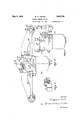
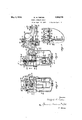
- Fig. l is a plan View of the present invention attached to the cylinder head, a part of which is shown in section.
- Fig. 2 is a side elevation looking toward the engine block.
- Fig. 3 is an end elevation of the carburetor unit viewed from the right in Fig. 2.
- Fig. 4 is a section on the line 4-4 of Fig. 2.
- Fig. 5 is a section on the line 5-5 of Fig. 4.
- Fig. 6 is a section on the line 6-6 of Fig. 4.
- Fig. 7 is a fragmentary section on the line 77 of Fig. 4. i
- Fig. 8 is a detail View showing the float valve in section.
- the device disclosed herein comprises a manifold indicated in its entirety by the reference character 10 and having three outlet passages 12, 14, and 16 each of which is adapted to communicate with one of the ports 18 of a multicylinder engine. Each portserves two adjacent cylinders through present valve ports 20a and 206, as clearly indicated in Fig. 1.
- the cylinder head is shown in three separate fragments 22, but it will'be understood that it may be an integral structure.
- the branches 12, 14 and 16 are each provided with an attaching flange 24 for attaching the manifold to the engine block in the usual manner. Adjacent its inlet the manifold is provided with a flange 26 to which may be secured the main carburetor unit, as shown in Fig. 4.
- the main carburetor unit comprises a main housing 28 in the form of a single casting which is provided with an attaching flange 30 of the same shape as the flange 26 and is adapted to be secured to said flange 26 by 7,
- An air inlet horn 34 the flow of air through which is regulated in a manner later described, is secured in position over an opening in the upper wall of the housing 28 by screws 36 which pass through flanges 38 and 40 on the air horn and main housing respectively.
- a sheet metal fuel bowl 46 is held tight against an annular shoulder 48 on a skirt 49 depending from the main housing by means of a screw 50 screwed into a post 52 depending from and integral with the casting 42.
- a gasket 54 is provided to prevent leakage around the screw.
- a fuel pipe (not shown) leading to a main source of fuel supply is adapted to be connected to a. boss 56 projecting from the housing 28 and having a fuel channel 58 bored therein.
- This fuel channel communicates with a vertical fuel channel 60 into the lower end of which a nipple 62 provided with a fuel passage therethrough is secured.
- This nipple is provided with lateral fuel outlets 64 through which the fuel flows into the fuel bowl and the flow of fuel is controlled by a valve 66 cooperating with a valve seat 68 in the nipple 62, the operation of the valve being controlled by a float 7 O pivoted at 7 2 and operating in the usual manner to maintain a substantially constant level of fuel within the fuel bowl.
- Fuel is conducted from the fuel bowl to a plurality of primary fuel nozzles 74 projecting into mixture passages formed in the central part of the main hous ng, and indicated in their entirety by the reference numeral 76.
- the mixing chamber For convenience that part of each passage 7 6 adjacent the nozzle is termed the mixing chamber and is indicated by the reference numeral 77.
- the casting 42 is provided with a dependingtubular portion 7 8 having a vertical fuel channel formed therein which connects at its upper end with a horizontal fuel channel 82 communicating with each of the fuel nozzles through holes 84. Fuel is admitted to the channel 80 through the metering orifice 86 which regulates the flow of fuel at all engine speeds.
- Fuel is lifted from the fuel bowl through the nozzles 7 4 to the mix ng chambers by the suction maintained therein. ⁇ Vhen the throttle is moved toward closed position to reduce the engine speed there is a sudden reduction in the suction on the vertical column of fuel between the fuel bowl and the nozzles which might permit th s column of fuel to drop sufficiently to cause a temporary fuel starving of the engine unless means were provided to prevent the dropping of such column of fuel.
- a check valve 88 is received in an enlarged chamber 90 formed by the junction of the fuel channels 80 and 82 and at reduction of suction in the primary mixing chambers seats on an annular rib 83 projecting upwardly from the bottom of such chamber, preventing downward flow through the fuel channel 80.
- Each primary fuel nozzle is provided with a main fuel outlet 92 in the top of the nozzle and a secondary fuel outlet comprising two orifices 94 and 96 formed in the vertical wall of the nozzle and diametrically opposite each other as shown in Fig. 4.
- a secondary fuel outlet comprising two orifices 94 and 96 formed in the vertical wall of the nozzle and diametrically opposite each other as shown in Fig. 4.
- the suction is not enough to lift the fuel through the main fuel feeding orifice, the fuel at this time standing in the nozzle at a point between the top of the nozzle and the orifices 94 and 96 and flowing from such orifices by action of gravity.
- Each fuel nozzle is provided with a restricted fuel metering orifice 98.
- a single throttle valve 100 journalled in the housing 28 and provided with grooves 102 which register with the mixture passages 76.
- a spindle 104 Projecting from one end of the throttle valve is a spindle 104 to which an operating lever 106 is secured.
- An operating connection is adapted to be attached to the end of said arm 106 and to extend to a point convenient to the operator of the vehicle to permit manual operation of the throttle valve. end with a peripheral groove 108 which is engaged by the inner end of a set screw 110 adjustable in the wall of the housing 28 to prevent any longitudinal movement of the The throttle is provided at one throttle.
- the mixture passages 7 6 are open at the top and communicate with a. chamber 112 formed in the housing 28. Par titions 114 are provided in the lower part of this chamber to separate the three mixture passages, as indicated in Fig. 6.
- the passages 76 at their posterior ends, communicate with three smaller tubular passages 118 formed in the attaching flange 30 which is adapted to be secured to the manifold.
- These passages 118 communicate with three pasabove mentioned applications, and communicate with pipes 122 which are connected at one end to the outlet ends of the passages 120 and at the other end to elbows 124 detachably secured to the manifold branches 12 and 16 in any suitable manner.
- These elbows communicate with tubes 126 similar to the tube 121 and similarly secured in the manifold branches 12 and 16.
- Primary mixture is drawn by engine suction from the mixing chambers 76 through the above described pipe connections to the secondary mixing chambers.
- an air inlet 136 is provided. This air inlet is an elongated slot formed in a plate 138 secured to the housing 28, as shown in Fig. 4c.
- the air valve 128 is adjustably secured on a stem 1&0 mounted in a guide sleeve 142 fixed in the housing 28.
- a slidable sleeve 14 Surrounding the guide sleeve is a slidable sleeve 14 1, the lower end of which has secured thereto a disc 146 which constitutes a flange projecting outward from the sleeve H4 and provides a seat for the lower end of the air valve spring 132.
- This disc is adapted to be lifted to bring the upper end of sleeve 1 1% into engagement with the underside of the air valve to hold the valve against the seat 130 in order to check the carburetor.
- the means for lifting the disc 146 comprises an arm 148 secured to a rock shaft 150 rotatably mounted in the wall of the housing 28.
- the arm 1 18 is provided with two' pins 152 and s projecting from its inner end and the disc 1 16 is received between these pins.
- the shaft 150 projects through the wall of the housing and its outer end 156 is bent upwart 1y and constitutes an operating lever for rocking the shaft. At its upper end this lever is provided with a hole 158 in which some form of operating connection extending from a point convenient to the operator may be attached.
- An adjustable stop screw 160 is received in a lug 162 detachably secured to the air horn as indicated in Fig. 2. By adjustment of the stop screw the normal position of the sleeve led may be variably determined in order to regulate the tension of the spring 132. Ordinarily the stop screw is adjusted so that the air valve will be held open slightly during idling.
- Such means comprises a dash pot having a piston 164 secured to the lower end of the valve stem 14:0 and a cylinder 166 in which the piston slides, which is formed in the casting 12.
- a flanged coupling member 168 is secured to the end of the stem when the piston is clamped between the flange on said member and a nut 170 screwed on the lower end of the member 168.
- the lower end of the cylinder 166 is closed by a closure member 172 having an opening 174 in the center thereof which is closed by an upwardly opened check valve 176 which permits unretarded movement of the piston, but prevents the escape of fuel on the outward movement thereof, fuel escaping on such outward movement only on a leakage around the piston, thus retarding the opening movement of the valve.
- This dash pot prevents fluttering of the valve as well as leaning of the mixture.
- This means comprises a passage 180 formed in the housing 28 and communicating with all of the mixture passages 116, said passage 180 being enlarged to form the chamber 112 heretofore referred to, which extends over all of the passages 7 6 above the partitions 114..
- the passage 180 is normally closed by means of a flap valve 181 secured to a rock shaft 182 pivotally mounted in the upper portion of the passage 180.
- the opening of this valve is normally retarded by a dash pot until the engine suction efiective to open the valve becomes sufficient to overcome the resistance ofthe dash pot.
- the dash pot includes a cylinder 183 having a projecting flange 18 1 secured by screws 185 to the main housing.
- a piston 186 is slidably received within the cylinder and fits in said cylinder tightly enough to oppose the opening of the air valve 181 to such degree as is desired.
- a light spring 187 is received in the cylinder 183 below the piston 186, and is eiit'ective to move the valve 181 toward closed position on reduction of manifold suction.
- the secondary mixing chambers comprise Venturi tubes 190 or other flow accelerator elements.
- Venturi tubes 190 or other flow accelerator elements.
- Each venturi is provided with a projecting rib 192 which fits when the manifold is attached to the engine block both in the engine intake port and in a recess 19st formed in the associated branch of the manifold, he rib engaging shoulders 196 and 198 in the manifold and engine block respectively, when the device is assembled.
- the venturis produce a high suction at the ends of the constantly opened mixture passages creating in tl passages a relatively high suction and high velocity of flow therethrough.
- mixture passages 76 slope downwardly from the nozzles to the point where they join the horizontal passages 118, so that it will be impossible for liquid fuel to collect on the walls of these passages.
- the above described device is operable, for reasons set forth hereinafter, to secure proper distribution of the fuel under all conditions of operation and provides a mixture of proper proportions during acceleration whenever the throttl is opened to accelerate, irrespective of the speed at which the engine is operating.
- all the i ixture passes through the constantly open passages 118 and communicating pipe connections to the intake ports. A such speeds these passages are of sufficient capacity to supply a large enough quantity of fuel to operate the engine without loss in volumetric efliciency. Moreover, all.
- the air entering the carburetor is brought into contact with the fuel in a region of high suction, facilitating ese atomization and partial vaporization of the fuel; and also enabling satisfactory acceleration, since on opening of the throttle the resulting increased supply of mixture is conveyed to the intake ports almost immediately and without dilution.
- a separate mixing chamber for each intake port from which the mixture is carried at high velocity to a point adjacent the port, collection of liquid fuel on the walls of the mixture passages is prevented and equal distribution of the mixture is secured. This is substantially impossible with a carburetor having one mixing chamber supplying the mixture for all the intake ports through one manifold, because of fuel collection on the walls of the manifold and for other reasons.
- the valved passage 180 is opened, and the mixture which passes the throttle is divided into two parts, the heavier portion comprising liquid fuel which is neither vaporized nor atomized passing through passages 118 and associated pipe connections and the lighter portion, comprising vaporized and atomized fuel, passing through the passage 180 and the manifold.
- This lighter portion of the mixture does not condense sufficiently on the walls of the manifold to interfere materially with equal distribution, while the unvaporized portion being conveyed from three separate mixing chambers to points close to the intake ports, is also equally distributed to the various ylinders.
- that partof the mixure comprising vaporized and atomized fuel is properly combustible, its admission to the secondary mixing chambers for remixtnre with the unvaporized fuel therein does not temporarily weaken the mixture to present above described difficulty in acceleration.
- the structure disclosed tends to form a more homogeneous mixture by separating the mixture into its lighter and heavier portions and again mixing these portions together.
- the passage 180 maintains at all times a substantially constant suction in the secondary mixing chambers and, therefore, a substantially constant velocity of flow through the passages 118 and associated pipe connections.
- This suction and flow velocity may be varied by usin springs of different force to control the valve 184.
- a charge forming device for internal combustion engines comprising a mix' chamber, means for supplying fuel and a thereto, means effective under certain operating conditions for separating said mixture into its heavier and lighter constituents, separate means for conveying the heavier and lighter constituents of the mixture to a poi nt adjacent an engine intake port, means for remixing said heavier and lighter constituents of the mixture, and means for preventing the separation of the mixture as described under certain operating conditions.
- a charge forming device for internal combustion engines comprising a mixing chamber, means for supplying fuel and air thereto, means for separatingthe mixture into its heavier and lighter constituents, separate passages for conveying said heavier and lighter constituents of the mixture to the engine intake port and means in one of said passages for regulating the fiow therethrough.
- a charge forming device for internal combustion engines comprising a mixing chamber, means for supplying fuel and air thereto, means for separating the mixture into its heavier and lighter constituents, separate passages for conveying said heavier and lighter constituents of the mixture to the engine intake port and means in the passage through which the lighter portion of the mixture flows for regulating the flow therethrough.
- a charge forming device for internal combustion engines comprising a mixin bers with one thereto, means for separating the mixture into its heavier and lighter constituents, separate passages for conveying said heavier and lighter constituents of the mixture to the engine intake port and means normally closing the passage through which the lighter portion of the mixture flows, said means being adapted to open at higher engine speeds.
- a charge forming device for internal combustion engines comprising a mixing chamber, means for supplying fuel and air thereto, means for separating the mixture into its heavier and lighter constituents, separate passages for conveying said heavier and lighter constituents of the mixture to the engine intake port and a suction operated valve in one of said passages for regulating the flow therethrough.
- a charge forming device for internal combustion engines comprising a mixing chamber, means for supplying fuel and air thereto, means for separating the mixture into its heavier and lighter constituents, separate passages for conveying said heavier and lighter coi'istituents of the mixture to the engine intake port, valve in the passage through which the lighter portion of the mixture flows, and a spring holding said valve closed at low engine speeds and adapted to permit opening of the valve by engine suction at higher engine speeds.
- a charge forming device for a multicylinder internal combustion engine comp-rising a plurality of mixing chambers, means for supplying fuel and air thereto, a plurality of separate mixture passages each of which connects one of said mixing chambers with one of the engine intake ports, and asingle mixture passage connecting all of the mixing chambers with said intake ports.
- a charge forming device for a multicylinder internal combustion engine comprising a plurality of mixing chambers, means for supplying fuel and air thereto, a plurality of separate mixture passages each of which connects one of said mixing chamof the engine intake ports and a single mixture passage connecting all of the mixing chambers with said intake ports, and means controlling the flow through said passage.
- Acharge forming device for a multicylinder internal combustion engine comprising a plurality of mixing chambers, means for supplying fuel and air thereto, a. plurality of separate mixture conduits each of which connects one of said mixing chambers with one of the engine intake ports, said conduits being constantly open to permit flow therethrough at all times, a single mixture conduit connecting all of said mixing chambers with the engine intake port-s andmeans closing said conduit at low enginespeeds but adapted to open at higher engine speeds.
- chamber, means for supplying fuel and air combustion engines comprising a plurality of mixing chambers, means for supplying fuel and air thereto, a throttle controlling the flow therefrom, a plurality of primary mixture passages adapted to convey all of. the. mixture to the engine intake ports at low speed, a. secondary mixture passage eifective at higher speeds and adapted to receive mixture from all of said mixing chambers, and means for regulating the flow through said secondary mixture passage.
- a charge forming device for internal combustion engines comprising a plurality of mixing chambers, means for supplying fuel and air thereto, a throttle controlling the flow therefrom, a plurality of primary mixture passages adapted to convey all of the mixture to the engine intake ports at low speed, a secondary mixture passage effective at higher speeds and adapted to receive mixture from all of said mixing chambers, and an automatically'operated valve in said secondary mixture passage to control the flow therethrough.
- a charge forming device for internal combustion engines comprising a plurality of mixing chambers, means for supplying fuel and air thereto, a throttle controlling the flow therefrom, a plurality of primary mixture passages adapted to convey mixture from the several mixing chambers to the engine intake ports, and a secondary mixture passage communicating directly with all of the primary mixture passages, and effective under certain operating conditions to convey a part of the mixture to the said intake ports.
- a charge forming device for internal combustion engines comprising a plurality of mixing chambers, means for supplying fuel and air thereto, a throttle controlling the flow -therefrom a aluralit of rimar mixture passages, each of which communicates directly with one of said mixing chambers and is adapted to convey mixture to one of the engine intake ports, and a secondary mixture passage communicating with all the said primary mixture passages and conveying mixture therefrom to the said intake ports under certain operating conditions.
- a charge forming device for internal combustion engines comprising a plurality of mixing chambers, means for supplying fuel and air thereto, a throttle controlling the flow therefrom, a plurality of primary mixture passages, each of which communicates directly with one of said mixing chambers and is adapted to convey mixture to one of the engine intake ports, a secondary mixture passage communicating with all said primary mixture passages to convey mixture therefrom to said intake ports under certain operating conditions, and a suction operated valve normally closing the secondary mixture passage, but adapted to be opened at relatively high engine speeds to render said passage efiective.
- a charge forming device for internal combustion engines comprising a plurality of mixing chambers, a plurality of relatively small primary mixture passages conveying the mixture from said chambers to the engine intake ports, and a single relatively large secondary air passage adapted to be rendered efiective to convey the mixture from said chambers to said intake ports under certain operating conditions.
- a charge forming device for internal combustion engines comprising a plurality of mixing chambers, a plurality of relatively small primary mixture passages conveying the mixture from said chambers to the engine intake ports, a single relatively large secondary air passage for conveying the mixture from said mixing chambers to said intake ports under certain operating conditions, and means for rendering the primary and secondary mixture passages effective seriatim.
- a charge forming device for internal combustion engines comprising a plurality of mixing chambers, a plurality of relatively small primary mixture passages for conveying all of the mixture to the engine intake ports at low engine speeds and a relatively large secondary mixture passage which is rendered elfective at higher engine speeds to convey mixture to said intake ports whereby the velocity of the mixture is maintained relatively high and substantially constant at all times.
Landscapes
- Engineering & Computer Science (AREA)
- Chemical & Material Sciences (AREA)
- Combustion & Propulsion (AREA)
- Mechanical Engineering (AREA)
- General Engineering & Computer Science (AREA)
- Control Of The Air-Fuel Ratio Of Carburetors (AREA)
Description
W. H. TEETER W Alma e 1 m J 9 .1 m M w N mm m vs M m g NNQ y/ m T S km on w E w 8 1 x a m.. ms in m May 3, 1932.
I CHARGE FORMING DEVICE May 3, 1932. w. H; TEETER CHARGE FORMING DEVICE 3 Sheets-Sheet 2 Filed Sept. 25, 1928 type.
Patented May 3, 1932 PATENT Fries;
WILFORD H. TEETER, OF DAYTON, OHIO, ASSIGNOR, BY MESNE ASSIGNMENTS, 'IO DEL-CO PRODUCTS CORPORATION, OF DAYTON, OHIO, A CORPORATION OF DELAWARE CHARGE FORMING DEVICE Application filed September 25, 1928. Serial No. 308,243.
This invention relates to charge forming device for internal combustion engines, and more particularly to a charge forming device for a multi-cylinder engine, which comprises .3 a plurality of primary mixing chambers one all operating conditions and to secure equal distribution of this mixture to the various engine cylinders.
It is one object of the present invention to provide means to secure a more homogeneous mixture of fuel and air under all operating conditions than is formed by prior devices of this character, to secure equal distribution and delivery of this mixture to the various engine intake ports, and to provide a device for effecting these results which is simpler in construction, easier to manufacture and cheaper than earlier devlces of thls similar A further object of the invention is to provide a device of simple construction which is effective to provide a mixture of proper proportions during the acceleration period immediately following an opening movement of the throttle.
According to this invention these objects are accomplished by the provision of a plurality of mixing chambers each of which has a separate fuel nozzle and all of which are controlled by a single throttle in combination with means for separating the mixture under certain operating conditions, at a point beyond the throttle, into its heavier and lighter constituents, and means for conveying these separate parts of the mixture through separate conduits to secondary mixing chambers iocated adjacent the engine intake ports when the separate portions of the mixture are reunited to be carried into the combustion chambers.
ing proper proportions of fuel and air under Further objects and advantages of the present invention will be apparent from the following description, reference being had to the accompanying drawings, wherein a preferred form of embodiment of the invention is clearly shown.
In the drawings: a
Fig. l is a plan View of the present invention attached to the cylinder head, a part of which is shown in section.
Fig. 2 is a side elevation looking toward the engine block.
Fig. 3 is an end elevation of the carburetor unit viewed from the right in Fig. 2.
Fig. 4 is a section on the line 4-4 of Fig. 2. Fig. 5 is a section on the line 5-5 of Fig. 4. Fig. 6 is a section on the line 6-6 of Fig. 4. Fig. 7 is a fragmentary section on the line 77 of Fig. 4. i
Fig. 8 is a detail View showing the float valve in section.
The device disclosed herein comprises a manifold indicated in its entirety by the reference character 10 and having three outlet passages 12, 14, and 16 each of which is adapted to communicate with one of the ports 18 of a multicylinder engine. Each portserves two adjacent cylinders through present valve ports 20a and 206, as clearly indicated in Fig. 1. The cylinder head is shown in three separate fragments 22, but it will'be understood that it may be an integral structure. The branches 12, 14 and 16 are each provided with an attaching flange 24 for attaching the manifold to the engine block in the usual manner. Adjacent its inlet the manifold is provided with a flange 26 to which may be secured the main carburetor unit, as shown in Fig. 4.
The main carburetor unit comprises a main housing 28 in the form of a single casting which is provided with an attaching flange 30 of the same shape as the flange 26 and is adapted to be secured to said flange 26 by 7,
screws 82. An air inlet horn 34, the flow of air through which is regulated in a manner later described, is secured in position over an opening in the upper wall of the housing 28 by screws 36 which pass through flanges 38 and 40 on the air horn and main housing respectively. A casting 42 having certain dash pot chambers and fuel passages, described in detail hereinafter, formed therein is secured by screws 44 to the lower wall of the housing 28. A sheet metal fuel bowl 46 is held tight against an annular shoulder 48 on a skirt 49 depending from the main housing by means of a screw 50 screwed into a post 52 depending from and integral with the casting 42. A gasket 54 is provided to prevent leakage around the screw.
A fuel pipe (not shown) leading to a main source of fuel supply is adapted to be connected to a. boss 56 projecting from the housing 28 and having a fuel channel 58 bored therein. This fuel channel communicates with a vertical fuel channel 60 into the lower end of which a nipple 62 provided with a fuel passage therethrough is secured. This nipple is provided with lateral fuel outlets 64 through which the fuel flows into the fuel bowl and the flow of fuel is controlled by a valve 66 cooperating with a valve seat 68 in the nipple 62, the operation of the valve being controlled by a float 7 O pivoted at 7 2 and operating in the usual manner to maintain a substantially constant level of fuel within the fuel bowl.
Fuel is conducted from the fuel bowl to a plurality of primary fuel nozzles 74 projecting into mixture passages formed in the central part of the main hous ng, and indicated in their entirety by the reference numeral 76. For convenience that part of each passage 7 6 adjacent the nozzle is termed the mixing chamber and is indicated by the reference numeral 77. To enable the fuel to flow from the fuel bowl to the primary nozzles the casting 42is provided with a dependingtubular portion 7 8 having a vertical fuel channel formed therein which connects at its upper end with a horizontal fuel channel 82 communicating with each of the fuel nozzles through holes 84. Fuel is admitted to the channel 80 through the metering orifice 86 which regulates the flow of fuel at all engine speeds.
Fuel is lifted from the fuel bowl through the nozzles 7 4 to the mix ng chambers by the suction maintained therein. \Vhen the throttle is moved toward closed position to reduce the engine speed there is a sudden reduction in the suction on the vertical column of fuel between the fuel bowl and the nozzles which might permit th s column of fuel to drop sufficiently to cause a temporary fuel starving of the engine unless means were provided to prevent the dropping of such column of fuel. To prevent this action a check valve 88 is received in an enlarged chamber 90 formed by the junction of the fuel channels 80 and 82 and at reduction of suction in the primary mixing chambers seats on an annular rib 83 projecting upwardly from the bottom of such chamber, preventing downward flow through the fuel channel 80.
Each primary fuel nozzle is provided with a main fuel outlet 92 in the top of the nozzle and a secondary fuel outlet comprising two orifices 94 and 96 formed in the vertical wall of the nozzle and diametrically opposite each other as shown in Fig. 4. At hi her speeds there is sufficient suction in the primary mixing chambers to cause fuel to flow from the main fuel outlet in the top of each nozzle as well as from the holes 94 and 96. At idle or very low speed, however, the suction is not enough to lift the fuel through the main fuel feeding orifice, the fuel at this time standing in the nozzle at a point between the top of the nozzle and the orifices 94 and 96 and flowing from such orifices by action of gravity. Each fuel nozzle is provided with a restricted fuel metering orifice 98.
There are three primary mixture passages 76 which are parallel to each other and close together as indicated in Fig. 7. The flow of mixture through these passages is controlled. by a single throttle valve 100 journalled in the housing 28 and provided with grooves 102 which register with the mixture passages 76. Projecting from one end of the throttle valve is a spindle 104 to which an operating lever 106 is secured. An operating connection is adapted to be attached to the end of said arm 106 and to extend to a point convenient to the operator of the vehicle to permit manual operation of the throttle valve. end with a peripheral groove 108 which is engaged by the inner end of a set screw 110 adjustable in the wall of the housing 28 to prevent any longitudinal movement of the The throttle is provided at one throttle. At a point immediately posterior to the throttle valve the mixture passages 7 6 are open at the top and communicate with a. chamber 112 formed in the housing 28. Par titions 114 are provided in the lower part of this chamber to separate the three mixture passages, as indicated in Fig. 6. The passages 76, at their posterior ends, communicate with three smaller tubular passages 118 formed in the attaching flange 30 which is adapted to be secured to the manifold. These passages 118 communicate with three pasabove mentioned applications, and communicate with pipes 122 which are connected at one end to the outlet ends of the passages 120 and at the other end to elbows 124 detachably secured to the manifold branches 12 and 16 in any suitable manner. These elbows communicate with tubes 126 similar to the tube 121 and similarly secured in the manifold branches 12 and 16. Primary mixture is drawn by engine suction from the mixing chambers 76 through the above described pipe connections to the secondary mixing chambers.
Substantially all of the air entering the carburetor flows through the air horn 34, the flow therethrough being controlled by an air valve 128, normally held against a seat 130 by a compression spring 132. Air flows past the valve into a main air cham er 134 formed in the housing 28, and from such chamber into the mixing chambers all of which communicate with the air chamber 134.
When the carburetor is choked to start the engine the air valve 128 is held against its seat to completely close the main air inlet by means presently described. To provide sufficient air to carry the starting fuel from the primary nozzles to the engine when the carburetor is choked as described, an air inlet 136 is provided. This air inlet is an elongated slot formed in a plate 138 secured to the housing 28, as shown in Fig. 4c.
The air valve 128 is adjustably secured on a stem 1&0 mounted in a guide sleeve 142 fixed in the housing 28. Surrounding the guide sleeve is a slidable sleeve 14 1, the lower end of which has secured thereto a disc 146 which constitutes a flange projecting outward from the sleeve H4 and provides a seat for the lower end of the air valve spring 132. This disc is adapted to be lifted to bring the upper end of sleeve 1 1% into engagement with the underside of the air valve to hold the valve against the seat 130 in order to check the carburetor. The means for lifting the disc 146 comprises an arm 148 secured to a rock shaft 150 rotatably mounted in the wall of the housing 28. The arm 1 18 is provided with two' pins 152 and s projecting from its inner end and the disc 1 16 is received between these pins. The shaft 150 projects through the wall of the housing and its outer end 156 is bent upwart 1y and constitutes an operating lever for rocking the shaft. At its upper end this lever is provided with a hole 158 in which some form of operating connection extending from a point convenient to the operator may be attached. An adjustable stop screw 160 is received in a lug 162 detachably secured to the air horn as indicated in Fig. 2. By adjustment of the stop screw the normal position of the sleeve led may be variably determined in order to regulate the tension of the spring 132. Ordinarily the stop screw is adjusted so that the air valve will be held open slightly during idling.
On opening movement of the throttle valve the suction in the air chamber 134 is increased and the air valve is opened against the closing force of its spring 132, admi ting a sur'licient quantity of air to the mixing chambers 77 to temporarily lean the mixture in the secondary carburetors sufficiently to cause improper engine operation unless means are provided to retard the opening movement of the opening of the valve. Such means comprises a dash pot having a piston 164 secured to the lower end of the valve stem 14:0 and a cylinder 166 in which the piston slides, which is formed in the casting 12. To secure the piston to the stem a flanged coupling member 168 is secured to the end of the stem when the piston is clamped between the flange on said member and a nut 170 screwed on the lower end of the member 168. The lower end of the cylinder 166 is closed by a closure member 172 having an opening 174 in the center thereof which is closed by an upwardly opened check valve 176 which permits unretarded movement of the piston, but prevents the escape of fuel on the outward movement thereof, fuel escaping on such outward movement only on a leakage around the piston, thus retarding the opening movement of the valve. This dash pot prevents fluttering of the valve as well as leaning of the mixture.
In addition to the pipe connections previously described for conveying the mixture from the mixing chambers 77 to the secondary mixing chambers hereinafter described, other means are provided to convey a part of the mixture formed in the mixing chambers 77 to said secondary mixing chambers under certain operating conditions. This means comprises a passage 180 formed in the housing 28 and communicating with all of the mixture passages 116, said passage 180 being enlarged to form the chamber 112 heretofore referred to, which extends over all of the passages 7 6 above the partitions 114.. At its outlet end the passage 180 communicates with the inlet of the manifold 10. The passage 180 is normally closed by means of a flap valve 181 secured to a rock shaft 182 pivotally mounted in the upper portion of the passage 180. The opening of this valve is normally retarded by a dash pot until the engine suction efiective to open the valve becomes sufficient to overcome the resistance ofthe dash pot. The dash pot includes a cylinder 183 having a projecting flange 18 1 secured by screws 185 to the main housing. A piston 186 is slidably received within the cylinder and fits in said cylinder tightly enough to oppose the opening of the air valve 181 to such degree as is desired. A light spring 187 is received in the cylinder 183 below the piston 186, and is eiit'ective to move the valve 181 toward closed position on reduction of manifold suction. l/Vhen the engine is running relatively slowly and the throttle 100 is only slightly opened, the engine suction on the engine side of the valve 181 is very high but at the same time this high suction is communicated through the constantly open mixture passage to the anterior side of the valve 181 so that i the force'which is actually effective to open the valve is very slight and insuiiicient to overcome the resistance of the dash pot. As the throttle is opened the suction on the engine side of said valve is reduced, but at the same time the suction between the valve and the throttle is reduced more rapidly so that the force effective to open the valve is increased as the throttle opens and the engine speed increases and some predetermined engine speed becomes sufficient to overcome the resistance of the dash pot and opens the valve, the degree of opening depending on the pressure differential between opposite sides of the valve. As the throttle is moved toward closed position and this pressure differential becomes less, the spring 187 is efiective to move the valve toward closed position and, finally to completely close said valve.
The secondary mixing chambers comprise Venturi tubes 190 or other flow accelerator elements. There are three of these Venturi tubes which are identical in construction and are positioned in the branches 12, 14 and 16 of the manifold 10, in such relation to the primary mixing tube,that thepoint of greatest depression or suction in each Venturi tube is immediately adjacent the outlet of the constantly open mixture passage which is associated therewith. Each venturi is provided with a projecting rib 192 which fits when the manifold is attached to the engine block both in the engine intake port and in a recess 19st formed in the associated branch of the manifold, he rib engaging shoulders 196 and 198 in the manifold and engine block respectively, when the device is assembled. The venturis produce a high suction at the ends of the constantly opened mixture passages creating in tl passages a relatively high suction and high velocity of flow therethrough. i
It will be noted that the mixture passages 76 slope downwardly from the nozzles to the point where they join the horizontal passages 118, so that it will be impossible for liquid fuel to collect on the walls of these passages.
The above described device is operable, for reasons set forth hereinafter, to secure proper distribution of the fuel under all conditions of operation and provides a mixture of proper proportions during acceleration whenever the throttl is opened to accelerate, irrespective of the speed at which the engine is operating. At all engine speeds lower than that at which the valve 181 opens, all the i ixture passes through the constantly open passages 118 and communicating pipe connections to the intake ports. A such speeds these passages are of sufficient capacity to supply a large enough quantity of fuel to operate the engine without loss in volumetric efliciency. Moreover, all. the air entering the carburetor is brought into contact with the fuel in a region of high suction, facilitating ese atomization and partial vaporization of the fuel; and also enabling satisfactory acceleration, since on opening of the throttle the resulting increased supply of mixture is conveyed to the intake ports almost immediately and without dilution. Further, by the provision of a separate mixing chamber for each intake port, from which the mixture is carried at high velocity to a point adjacent the port, collection of liquid fuel on the walls of the mixture passages is prevented and equal distribution of the mixture is secured. This is substantially impossible with a carburetor having one mixing chamber supplying the mixture for all the intake ports through one manifold, because of fuel collection on the walls of the manifold and for other reasons.
it higher engine speeds the constantly open passages are of insufficient capacity to supply enough mixture to meet the engine demands and additional mixture must be supplied. It has been the practice heretofore in charge forming devices of this character, to open an air throttle at a predetermined speed to admit additional air to the secondary mixing chambers at such higher engine speeds to mix with the primary mixture therein to supply the necessary quantity of mixture to the engine. A structure of this character is fully disclosed in the copending application previously referred to. The admission of this secondary air makes it diflicult to secure satisfactory engine operation during acceleration at all speeds above that at which the air throttle begins to open because the secondary air, being much lighter than the primary mixture, reaches the secondary mixing chambers before the increased quantity of fuel resulting from the opening of the throttle to accelerate. This tends to lean the mixture temporarily, which causes the engine to miss with loss of power instead of the desired increase in power.
According to the present invention, instead of admitting pure air to the secondary mixing chambers at speeds above those at which the constantly open passages 118 and of sulficient capacity to supply enough mixture to meet the engine demand, the valved passage 180 is opened, and the mixture which passes the throttle is divided into two parts, the heavier portion comprising liquid fuel which is neither vaporized nor atomized passing through passages 118 and associated pipe connections and the lighter portion, comprising vaporized and atomized fuel, passing through the passage 180 and the manifold. This lighter portion of the mixture does not condense sufficiently on the walls of the manifold to interfere materially with equal distribution, while the unvaporized portion being conveyed from three separate mixing chambers to points close to the intake ports, is also equally distributed to the various ylinders. Also, since that partof the mixure comprising vaporized and atomized fuel is properly combustible, its admission to the secondary mixing chambers for remixtnre with the unvaporized fuel therein does not temporarily weaken the mixture to present above described difficulty in acceleration.
In addition to the above described advantages of the present invention in effecting superior distribution and acceleration, the structure disclosed tends to form a more homogeneous mixture by separating the mixture into its lighter and heavier portions and again mixing these portions together.
Also the provision of the spring held valve the passage 180 maintains at all times a substantially constant suction in the secondary mixing chambers and, therefore, a substantially constant velocity of flow through the passages 118 and associated pipe connections. This suction and flow velocity may be varied by usin springs of different force to control the valve 184.
While the form of embodiment of the presentinvention as herein disclosed, constitutes a preferred form, it is to be understood that other forms might be adopted, all coming within the scope of the claims which follow.
What is claimee is as follows:
1. A charge forming device for internal combustion engines comprising a mix' chamber, means for supplying fuel and a thereto, means effective under certain operating conditions for separating said mixture into its heavier and lighter constituents, separate means for conveying the heavier and lighter constituents of the mixture to a poi nt adjacent an engine intake port, means for remixing said heavier and lighter constituents of the mixture, and means for preventing the separation of the mixture as described under certain operating conditions.
2. A charge forming device for internal combustion engines comprising a mixing chamber, means for supplying fuel and air thereto, means for separatingthe mixture into its heavier and lighter constituents, separate passages for conveying said heavier and lighter constituents of the mixture to the engine intake port and means in one of said passages for regulating the fiow therethrough.
3. A charge forming device for internal combustion engines comprising a mixing chamber, means for supplying fuel and air thereto, means for separating the mixture into its heavier and lighter constituents, separate passages for conveying said heavier and lighter constituents of the mixture to the engine intake port and means in the passage through which the lighter portion of the mixture flows for regulating the flow therethrough.
at. A charge forming device for internal combustion engines comprising a mixin bers with one thereto, means for separating the mixture into its heavier and lighter constituents, separate passages for conveying said heavier and lighter constituents of the mixture to the engine intake port and means normally closing the passage through which the lighter portion of the mixture flows, said means being adapted to open at higher engine speeds.
5. A charge forming device for internal combustion engines comprising a mixing chamber, means for supplying fuel and air thereto, means for separating the mixture into its heavier and lighter constituents, separate passages for conveying said heavier and lighter constituents of the mixture to the engine intake port and a suction operated valve in one of said passages for regulating the flow therethrough.
6. A charge forming device for internal combustion engines comprising a mixing chamber, means for supplying fuel and air thereto, means for separating the mixture into its heavier and lighter constituents, separate passages for conveying said heavier and lighter coi'istituents of the mixture to the engine intake port, valve in the passage through which the lighter portion of the mixture flows, and a spring holding said valve closed at low engine speeds and adapted to permit opening of the valve by engine suction at higher engine speeds.
7. A charge forming device for a multicylinder internal combustion engine comp-rising a plurality of mixing chambers, means for supplying fuel and air thereto, a plurality of separate mixture passages each of which connects one of said mixing chambers with one of the engine intake ports, and asingle mixture passage connecting all of the mixing chambers with said intake ports.
8. A charge forming device for a multicylinder internal combustion engine comprising a plurality of mixing chambers, means for supplying fuel and air thereto, a plurality of separate mixture passages each of which connects one of said mixing chamof the engine intake ports and a single mixture passage connecting all of the mixing chambers with said intake ports, and means controlling the flow through said passage.
9. Acharge forming device for a multicylinder internal combustion engine comprising a plurality of mixing chambers, means for supplying fuel and air thereto, a. plurality of separate mixture conduits each of which connects one of said mixing chambers with one of the engine intake ports, said conduits being constantly open to permit flow therethrough at all times, a single mixture conduit connecting all of said mixing chambers with the engine intake port-s andmeans closing said conduit at low enginespeeds but adapted to open at higher engine speeds. chamber, means for supplying fuel and air combustion engines comprising a plurality of mixing chambers, means for supplying fuel and air thereto, a throttle controlling the flow therefrom, a plurality of primary mixture passages adapted to convey all of. the. mixture to the engine intake ports at low speed, a. secondary mixture passage eifective at higher speeds and adapted to receive mixture from all of said mixing chambers, and means for regulating the flow through said secondary mixture passage.
11. A charge forming device for internal combustion engines comprising a plurality of mixing chambers, means for supplying fuel and air thereto, a throttle controlling the flow therefrom, a plurality of primary mixture passages adapted to convey all of the mixture to the engine intake ports at low speed, a secondary mixture passage effective at higher speeds and adapted to receive mixture from all of said mixing chambers, and an automatically'operated valve in said secondary mixture passage to control the flow therethrough.
12. A charge forming device for internal combustion engines comprising a plurality of mixing chambers, means for supplying fuel and air thereto, a throttle controlling the flow therefrom, a plurality of primary mixture passages adapted to convey mixture from the several mixing chambers to the engine intake ports, and a secondary mixture passage communicating directly with all of the primary mixture passages, and effective under certain operating conditions to convey a part of the mixture to the said intake ports.
13. A charge forming device for internal combustion engines comprising a plurality of mixing chambers, means for supplying fuel and air thereto, a throttle controlling the flow -therefrom a aluralit of rimar mixture passages, each of which communicates directly with one of said mixing chambers and is adapted to convey mixture to one of the engine intake ports, and a secondary mixture passage communicating with all the said primary mixture passages and conveying mixture therefrom to the said intake ports under certain operating conditions.
14. A charge forming device for internal combustion engines comprising a plurality of mixing chambers, means for supplying fuel and air thereto, a throttle controlling the flow therefrom, a plurality of primary mixture passages, each of which communicates directly with one of said mixing chambers and is adapted to convey mixture to one of the engine intake ports, a secondary mixture passage communicating with all said primary mixture passages to convey mixture therefrom to said intake ports under certain operating conditions, and a suction operated valve normally closing the secondary mixture passage, but adapted to be opened at relatively high engine speeds to render said passage efiective. V
15. A charge forming device for internal combustion engines comprising a plurality of mixing chambers, a plurality of relatively small primary mixture passages conveying the mixture from said chambers to the engine intake ports, and a single relatively large secondary air passage adapted to be rendered efiective to convey the mixture from said chambers to said intake ports under certain operating conditions.
16. A charge forming device for internal combustion engines comprising a plurality of mixing chambers, a plurality of relatively small primary mixture passages conveying the mixture from said chambers to the engine intake ports, a single relatively large secondary air passage for conveying the mixture from said mixing chambers to said intake ports under certain operating conditions, and means for rendering the primary and secondary mixture passages effective seriatim.
17. A charge forming device for internal combustion engines comprising a plurality of mixing chambers, a plurality of relatively small primary mixture passages for conveying all of the mixture to the engine intake ports at low engine speeds and a relatively large secondary mixture passage which is rendered elfective at higher engine speeds to convey mixture to said intake ports whereby the velocity of the mixture is maintained relatively high and substantially constant at all times.
In testimony whereof I hereto afiix my signature.
l/VILFORD H. TEETER.
Priority Applications (1)
| Application Number | Priority Date | Filing Date | Title |
|---|---|---|---|
| US308243A US1856736A (en) | 1928-09-25 | 1928-09-25 | Charge forming device |
Applications Claiming Priority (1)
| Application Number | Priority Date | Filing Date | Title |
|---|---|---|---|
| US308243A US1856736A (en) | 1928-09-25 | 1928-09-25 | Charge forming device |
Publications (1)
| Publication Number | Publication Date |
|---|---|
| US1856736A true US1856736A (en) | 1932-05-03 |
Family
ID=23193169
Family Applications (1)
| Application Number | Title | Priority Date | Filing Date |
|---|---|---|---|
| US308243A Expired - Lifetime US1856736A (en) | 1928-09-25 | 1928-09-25 | Charge forming device |
Country Status (1)
| Country | Link |
|---|---|
| US (1) | US1856736A (en) |
Cited By (3)
| Publication number | Priority date | Publication date | Assignee | Title |
|---|---|---|---|---|
| US4240387A (en) * | 1978-08-10 | 1980-12-23 | Toyota Jidosha Kogyo Kabushiki Kaisha | Intake system of a multi-cylinder internal combustion engine |
| US4262639A (en) * | 1978-08-10 | 1981-04-21 | Toyota Jidosha Kogyo Kabushiki Kaisha | Intake system of a multi-cylinder internal combustion engine |
| US4445473A (en) * | 1978-04-13 | 1984-05-01 | Yamaha Hatsudoki Kabushiki Kaisha | Control of carburetor-supplied induction system |
-
1928
- 1928-09-25 US US308243A patent/US1856736A/en not_active Expired - Lifetime
Cited By (3)
| Publication number | Priority date | Publication date | Assignee | Title |
|---|---|---|---|---|
| US4445473A (en) * | 1978-04-13 | 1984-05-01 | Yamaha Hatsudoki Kabushiki Kaisha | Control of carburetor-supplied induction system |
| US4240387A (en) * | 1978-08-10 | 1980-12-23 | Toyota Jidosha Kogyo Kabushiki Kaisha | Intake system of a multi-cylinder internal combustion engine |
| US4262639A (en) * | 1978-08-10 | 1981-04-21 | Toyota Jidosha Kogyo Kabushiki Kaisha | Intake system of a multi-cylinder internal combustion engine |
Similar Documents
| Publication | Publication Date | Title |
|---|---|---|
| US2737935A (en) | Crankcase ventilator | |
| US1856736A (en) | Charge forming device | |
| US1904634A (en) | Charge forming device | |
| US1926019A (en) | Manifold for internal combustion engines | |
| US3233878A (en) | Charge forming apparatus | |
| US1911135A (en) | Charge forming device | |
| US2038157A (en) | Charge forming device | |
| US1937938A (en) | Charge forming device | |
| US1966329A (en) | Charge forming device | |
| US1960993A (en) | Charge forming device | |
| US2269949A (en) | Carburetor | |
| US1883096A (en) | Charge forming device | |
| US1854172A (en) | Charge forming device | |
| US1946608A (en) | Charge forming device | |
| US2138038A (en) | Charge forming device | |
| US1889069A (en) | Charge forming device | |
| US1883097A (en) | Charge forming device | |
| US1825381A (en) | Multiple carburetor charge forming device | |
| US1819526A (en) | Charge forming device | |
| US1179381A (en) | Carbureter. | |
| US1834198A (en) | Charge forming device | |
| US1939431A (en) | Charge forming device | |
| US1926020A (en) | Charge forming device | |
| US1450628A (en) | Carburetor | |
| US1944547A (en) | Carburetor |