US1856722A - Expansion joint for pavements and the like - Google Patents
Expansion joint for pavements and the like Download PDFInfo
- Publication number
- US1856722A US1856722A US365661A US36566129A US1856722A US 1856722 A US1856722 A US 1856722A US 365661 A US365661 A US 365661A US 36566129 A US36566129 A US 36566129A US 1856722 A US1856722 A US 1856722A
- Authority
- US
- United States
- Prior art keywords
- sections
- pavement
- expansible
- expansion
- crack
- Prior art date
- Legal status (The legal status is an assumption and is not a legal conclusion. Google has not performed a legal analysis and makes no representation as to the accuracy of the status listed.)
- Expired - Lifetime
Links
- 239000002184 metal Substances 0.000 description 21
- 238000004873 anchoring Methods 0.000 description 12
- 238000010276 construction Methods 0.000 description 11
- 230000015572 biosynthetic process Effects 0.000 description 6
- 238000005755 formation reaction Methods 0.000 description 6
- 230000008602 contraction Effects 0.000 description 5
- 239000000463 material Substances 0.000 description 5
- 210000002105 tongue Anatomy 0.000 description 4
- 229910000831 Steel Inorganic materials 0.000 description 3
- 239000010959 steel Substances 0.000 description 3
- 230000006835 compression Effects 0.000 description 2
- 238000007906 compression Methods 0.000 description 2
- 230000008030 elimination Effects 0.000 description 2
- 238000003379 elimination reaction Methods 0.000 description 2
- 208000027418 Wounds and injury Diseases 0.000 description 1
- 230000009471 action Effects 0.000 description 1
- 238000005452 bending Methods 0.000 description 1
- 230000008859 change Effects 0.000 description 1
- 230000000295 complement effect Effects 0.000 description 1
- 230000006378 damage Effects 0.000 description 1
- 239000000428 dust Substances 0.000 description 1
- 230000000694 effects Effects 0.000 description 1
- 208000014674 injury Diseases 0.000 description 1
- 230000002452 interceptive effect Effects 0.000 description 1
- 230000004048 modification Effects 0.000 description 1
- 238000012986 modification Methods 0.000 description 1
- 230000009972 noncorrosive effect Effects 0.000 description 1
- 239000002245 particle Substances 0.000 description 1
- 239000004576 sand Substances 0.000 description 1
- 239000002689 soil Substances 0.000 description 1
- 238000010408 sweeping Methods 0.000 description 1
Images


Classifications
-
- E—FIXED CONSTRUCTIONS
- E01—CONSTRUCTION OF ROADS, RAILWAYS, OR BRIDGES
- E01C—CONSTRUCTION OF, OR SURFACES FOR, ROADS, SPORTS GROUNDS, OR THE LIKE; MACHINES OR AUXILIARY TOOLS FOR CONSTRUCTION OR REPAIR
- E01C11/00—Details of pavings
- E01C11/02—Arrangement or construction of joints; Methods of making joints; Packing for joints
- E01C11/04—Arrangement or construction of joints; Methods of making joints; Packing for joints for cement concrete paving
- E01C11/14—Dowel assembly ; Design or construction of reinforcements in the area of joints
Definitions
- the present invention relates to concrete floors, pavements, sidewalks and the like, and is particularly concerned with expansion joints for such concrete structures.
- the concrete pavementsof the prior art are ordinarily constructed in a plurality of sections with cracks between the sections, and substantially larger expansion cracks located at regular intervals for the purpose of permitting the longitudinal expansion of the pavement under changes of temperature of the pavement.
- the separate sections of the pavement expand, there is a gradual sliding of the sections toward theexpansion crack or joint, but when the sections subsequently contract, they do not tend to return to their former position, with the result that the relatively wide expansion crack soon disappears and is divided among the plurality of cracks formed between the adjacent sections of the pavement, and it is practically impossible to prevent this action of the pavement sections in closing up the expansion joint.
- One of the objects'of the present invention is the elimination oi the foregoing diiiiculties and others, by the provision of an improved expansion joint of relatively simple and economicalfcnstruction, whichis adapted to permit relative movement between adjacent sections of the pavement, and to prevent the ⁇ filling of the cracksbetween the sections with dirtor other foreigr naterial.
- Another object of the invention is the provision of an improved expansion joint asse1nbly, including a simplied form of expansible member having a substantially V-shaped expansible portion and having anchoring for insuring the formation of separate sections of pavement, and aligning means carried by said division member for maintaining the separate sections of pavement in the same'plane, hile permitting expansion or contraction of the separate sections under changes of temperature.
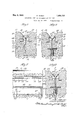
- Fig. 1 is a vertical sectional view'of a portion of a concrete pavement, iioor, sidewalk or the like, which is lequipped with an eX- pansion joint of the simplest type constructed according to the present invention
- Fig. 2 is a similar view of the expansion joint after the adjacent sections of the pavement have contracted, showing the parts in diierent position;
- Fig. 3 is a similar view of a modified form of construction, including a division plate for supporting the expansible member;
- Fig. 4 is a view in perspective of a por tion of the division plate of Fig. 3;
- Fig. 5 is a view similar to Fig. 3 of a modified form of construction, having a division plate with aligning formations and. an expansible member adapted to be supported upon the division plate;
- Fig. 6 is a similar sectional view of a modified form of construction, including a division plate with an aligning plate and special means of support for the division plate during the construction of the pavement;
- Fig. 7 is a vertical sectlonal view taken on the plane of the line 7-7.0f Fig. 8;
- Fig. 8 is a view similar to Fig. 6, showing the expansion joint after the pavement sections have contracted with the parts in a different position;
- Fig. 9 is a sectional view of a modified form of construction in which the pavement crack is protected above and below;
- Fig. 10 is a side elevation of the parting strip and supports shown in Fig. 9 apart from the pavement.
- Fig. 1, 10 and 11 indicate the adjacent portions of concrete sections of a pavement, and in this embodiment the secn tions may be provided with acrack 12 naturally formed as the result of stresses when the adjacent sections contract, or, formed by' means of a trowel or other toolwhenthe sections are laid.
- the expansible member 13 comprises a strip of non-corrosive sheet metal which is formed withan expansible central portion 14 and integral anchoring fianges 15 and 16 on each side of the expansible portion 14.
- the expansible portion ⁇ 14 preferably comprises a substantially V-shaped bend in the strip 13, extending longitudinally of the strip and preferably provided with a curve 17 lat the bottom of the V to facilitate bending without breaking of the metal.
- the upwardly extending diverging fianges 18 and 19 of the V-shaped member 14 are joined to downwardly extending fianges 20 and 21 adapted to extend into the adjacent sections 10 and 11 of concrete, and the downwardly extending flanges 20 and 21 are provided with anc oring formations 15 and 16 for securely anchoring the expansible member 13 in each of the concrete sections 10 and 11.
- the anchoring formations 15 and 16 may take any of a plurality of different forms, but in the preferred embodiment, the anchoring formations 15 and' 16 comprise horizontally extending ianges 15 and 16 with backwardly turned edges 22 and 23 for engaging in the concrete and preventing the withdrawal of the expansible member 13.
- the horizontally extending f'langes 15 and 16 provide a substantial area of support for the expansible mem- -pansible member 13 coverin t e upper porably rounded off to a surface substantially fiush with thel inner surface of the diverg- ⁇ ing flanges 18 and 19 to prevent injury to the corners of the sections by traffic, and to provide a finished appearance at the expansion joint.
- the concrete may extend upwardly between the flanges 20 and 21 of the expansible member 13, without interfering with the functions of the expansible member,
- the dirt or other foreign matter indicated at 26 will be prevented from entering the crack 12 and when the sections 10 and 11 expand again, the crack will be open to permit expansion of the pavement without producing compression stresses.
- the.v expansion joint illustrated in this figure includes an expansible member 13 of substantially the same form as that previously described, together with a division plate 27 for producing a definite line of division between the adjacent pavement sections 10 and 11, and for supporting the expansiblev member in place during the formation of the pavement.
- a short section of the division plate 27 is shown in 'to thelower surface of the V-shaped expan-l sible member 13.
- the tongues 29, 30 do not interfere with the operation ofthe expansible member 13 since the expansible member 13 is adapted to flex upward during contrac-- tion of the concrete, and it is contem lated that expansion cracks may be provi ed at other points in the concrete for permitting further expansion of the concrete sections.
- Such expansion cracks may be formed sub# i' stantially as shown in Fig. 2 with an extion of the crack.
- the division plate 31 illustrated in this embodiment comprises a strip of sheet metal which is formed with a longitudinally extending rib 32 of substan tial width having oblique side flanges 33 and 34.
- the division plate 31 forms a metal lined recess 36 in the pavement section 10 and a protuberance 35 extending along one edge of the pavement section '11, and adapted to engage within the recess 36 to maintain the alignment of the pavement sections 10 and 11, or to prevent settling of one section relative to the other.
- the expansible member 13 of this embodiment is of substantially the same form as that previously described,'ex ceptv the V-shaped expansible portion 14 is provided with an inwardly projecting, longitudinally extending integral rib 37 forming a groove 38 in the lower side of the expansible member 13 for receiving the upper edge of the division plate 31.
- the rib 37 of the expansible member 13 may slide upward on the division plate 31 when the pavement sections 10 and 11 contract under temperature changes.
- the expansible member 13 illustrated in this embodiment is Vsubstantially the same as that disclosed in v
- the division plate 39 of this modified form of expansion joint is preferably provided with a longitudinally extending rib 40 comprising side flanges 41 arid 42 of substantial width joined by the end flange 43.
- the longitudinally extending rib 40 forms a groove 44 which is adapted to receive an aligning member 45 comprising a metal plate slidably supported in the groove 44 and the plate 45 is of sufficient length to project out of the groove 44 into the adjacent concrete section 10.
- the division plate 39 is provided with the downwardly extending supporting lange46 and the ange 46 may be supported in a plurality of driven members such as stakes or pegs 47, having slots 48 to receive the division plate 39.
- rlhe division plate 39 thus forms a metal lined slot 44. the side walls of which are not tapered, so that the slot is in continuous slidable engagement with the aligning member or plate 45, and when the adjacent concrete sections 10 and 11 contract as shown in Fig. 8, the plate may slide in the groove 44 or the division plate 39 may slide,
- any of the expansion joints described herein may be used for either transverse joints in pavement or longitudinal joints, and the expansible member 13 is adapted to be used for maintaining the alignment of the ad'acent secf tions 10 and l1 under certain con itions.
- the present invention is applicable to joints in which the pavement sections are initially spaced from each other and therefore adapted to permit expansion of the sections, or joints in which the pavement sections are initially joined or in contact vso that the joint is intended to permit contraction of the sections. Since either of these types of joints will permit either expansion or contraction at certain temperatures, I employ the term expansion joint generically in the present specification and claims to include a structure performing either or both of these functions.
- an expansible joint for concrete pavement and the like which is adapted to prevent the filling up of expansion cracks or other cracks between adjacent sections of concrete, and the present expansion joint includes a sheet metal expansible member of relatively simple construction so that it may be economically manufactured.
- One of the important features of the present invention is the elimination of the parts of the prior complicated structures and the performance of their function'by a simplified structure which is sturdy and economical, without substantially increasing the cost.
- the aligning member 45 preferablv comprises a steel plate having substantially parallel upper and lower surfaces so that the plate may/ slidably engage the adjacent walls of the recess formed'in one or both ofthe concrete sections'lO and 11. Where the aligning member is tapered, the space between the aligning plate or projectionand its complementary recess, increasesin width as the sec- ,tions contract, and consequently the tapered aligning members do not perform the function of alignment and support as the crack between the sections widens.
- the aligning member is provided with substantially parallel. guiding surfaces such as those of the steel plate 45, the aligning member slidably engages in the concrete sections at all times, and positively prevents l any settling or vertical movement of one se:- tion relative to the other. lt is, of course, possible to provide aligning members 45 which have other shapes than the simple flat plate illustrated, provided such aligning v members have substantially parallel guiding surfaces, but the. .simple flat plate has additional advantages in that it may be most eco,-
- the crack 12 is protected by an expansible member 14 carried by the pavement sections 10 and 11 adjacent the top of the millent, and by a second expansible mem er 14 carried by the pavement sections adjacent the bottom ofthe pavement, thereby positively preventing foreign matter from entering the crack from either direction.
- expansible members may be used on either or both top or bottom of the pavement.
- the expansible members 14 may be provided with downwardly and inwardly turned anchoring flanges 50 forming a groove 51 which is adapted to receive a. horizontally extending flange 52 carried bv the parting strip 53.
- the parting strip 53 has a central portion similar to the parting strip of Figs. 6 to 8. beine formed with a longitudinally extending rib 4() forming a groove 42 adapted to receive the aligning member 43.
- the lower edge of lthe parting strip is provided with a similar horizontally extending flange 52 for engaging the expansible member 14 and in some embodiments of the invention, the flanges 52 may be spot welded, riveted or otherwise permanently secured to the adjacent flanges of the expansible inembers 14.
- the combined parting strip, aligning member. and expansible members may then be supported in place by a pluralitv of supporting members 54 comprising sticks or' pins similar to the sticks 47. but having slots 55 of a shane and a size sufficient to receive the parting strip and aligning member and support them upon the shoulders .56.
- a pavement or the like comprising a pair of sections having adjacent edges, and means for connecting said sections and preventing filling of a crack between said edges, comprising a flexible sheet metal member having a substantially V-shaped bend extending lon-y,
- pavement or the like comprising a pair of sections having adjacent edges, and means for connecting said sections and preventing filling ofA a crack between said edges, comprising a flexible sheet metal member having asiubstantially V-shaped bend extending longitudinally of said crack, and integral anchoring flanges extending into said pavement sections and formed on each side of sai d V-shaped bend, and a division plate comprising a sheet metal member having oppositely extending tongues formed along its upper edge to provide a support for said flexible metal member.
- a pavement or the like comprising a pair of sections havingadjacent edges, and means for connecting said sections and preventing filling of a crack between said edges, comprising a flexible sheet metal member having a substantially V-shaped bend extending longitudinally of said crack, and integral anchoring flanges extending into said pavement sections and formed on each side of said V-shaped bend, a division plate comprising a s'hkeet metal member having oppositely extending tongues formed along its upper edge to provide a support for said ⁇ flexible ,metal member, and a plurality of driven members having slots for receiving said division plate to support said division plate.
- a pavement or the like comprising a pair of sections having adjacent edges, and means for connecting said sections and preventing filling of a crack between said edges, comprising a flexible sheet metal member having a substantially V-shaped bend extending longitudinally of said crack, and integral anchoring flanges extending into said pavement sections and formed on each side of said V-shaped bend, a division plate comprising a sheet m-etal member having oppositely extending tongues formed along its upper edge to provide a support for said flexible metal member, said division plate having a longitudinally extending rib forming a slot substantially parallel to the pavement and means for aligning said sections, slidably mounted in said slot.
- An expansion joint assembly for concrete pavements or the like comprising a ilexible sheet metal member having a V- shaped groove formed longitudinally of said member, downwardly extending flanges on pair of sections with adjacent spaced edges Y said edges, an vexpansl le member located'adjacent one of the faces of said sections to close said crack at substantially the face and prevent ingress of foreign material to said crack, said expansible member comprising an integral sheet metal member, formed with a central longitudinally extending, laterally expansible portion, and with laterally projecting anchoring iiange's, extending into the body of said sections and secured therein, and a division plate for producing the expansion Crack between said sections a predetermined point in substantial alignment with .the expansible portion of said member, said division plate having a plurality of oppositely.
- a pavement or the like comprising a pair of sections with adjacent spaced edges forming an open expansion crack between said edges, an expansible member located adjacent one of the faces of said sections to close said crack at substantially the face and prevent ingress of foreign material to said crack, said expansible member comprising an integral sheet metal member, formed with a central longitudinally extending, laterally ex- ⁇ pansible portion, and with laterally projecting anchoring iianges, extending into the body7 of said sections and secured therein, and a division plate for producing the expansion crack between said sections a predetermined point in substantial alignment with the expansible portion of said member, said division plate comprising a fiat sheet metal member having slits in its upper edge and having the iianges between said slits bent alternately in opposite directions to form a supporting surface for said expansible member.
Landscapes
- Engineering & Computer Science (AREA)
- Architecture (AREA)
- Civil Engineering (AREA)
- Structural Engineering (AREA)
- Road Paving Structures (AREA)
Description
May 3, 1932- c. OLDER l,856,722
Www/M.
May 3, 1932. c. OLDER 1,856,722
EXPANSION JOINT FOR PAVEMENTS AND THE LIKE Filed May 24, 1929' 3 Sheets-Sheet 2 A @MWWMYM May 3, 1932 c. OLDER ,856,722
EXPANSION JOINT FOR PAVEMENTS AND THE LIKE Filed May 24, 1929 3 Sheets-Sheet 3 fa O Y 50 Patented May 3, 1932 CLIFFORD emana, or wrnnnfrfrn rnralvors EXPANSION JUINT FOR PAVEMENTS ND THE lll: i;
Application :tiled May 24, 1929. Serial. No. 365,661.
The present invention relates to concrete floors, pavements, sidewalks and the like, and is particularly concerned with expansion joints for such concrete structures.
The concrete pavementsof the prior art are ordinarily constructed in a plurality of sections with cracks between the sections, and substantially larger expansion cracks located at regular intervals for the purpose of permitting the longitudinal expansion of the pavement under changes of temperature of the pavement. lVhen the separate sections of the pavement expand, there is a gradual sliding of the sections toward theexpansion crack or joint, but when the sections subsequently contract, they do not tend to return to their former position, with the result that the relatively wide expansion crack soon disappears and is divided among the plurality of cracks formed between the adjacent sections of the pavement, and it is practically impossible to prevent this action of the pavement sections in closing up the expansion joint.
The open expansion joints and cracks between adjacent sections soon become filled with dust, soil, iioor sweepings or sand particles, and as this material is generally incompressible it follows that when expansion again takes place, the joints cannot close between the adjacent sections and the whole series of sections is pushed still furtherto- Award the expansion joint until eventually all of the joints, including the expansion joint, become filled with hard packed unyielding material. The urpose of the expansion joint is then de cated and further expansion of the concrete sets up compression stresses as great. as would be the case had no expansion joint been provided in the firstplace.
One of the objects'of the present invention is the elimination oi the foregoing diiiiculties and others, by the provision of an improved expansion joint of relatively simple and economicalfcnstruction, whichis adapted to permit relative movement between adjacent sections of the pavement, and to prevent the`filling of the cracksbetween the sections with dirtor other foreigr naterial.
Another object of the invention is the provision of an improved expansion joint asse1nbly, including a simplied form of expansible member having a substantially V-shaped expansible portion and having anchoring for insuring the formation of separate sections of pavement, and aligning means carried by said division member for maintaining the separate sections of pavement in the same'plane, hile permitting expansion or contraction of the separate sections under changes of temperature.
Other objects and advantages of the invention will be apparent from the following description and from the accompanying drawings, in which similar characters of reference indicate simar parts throughout the several views.
Referring to the drawings, of which there are two sheets;
Fig. 1 is a vertical sectional view'of a portion of a concrete pavement, iioor, sidewalk or the like, which is lequipped with an eX- pansion joint of the simplest type constructed according to the present invention;
Fig. 2 is a similar view of the expansion joint after the adjacent sections of the pavement have contracted, showing the parts in diierent position;
Fig. 3 is a similar view of a modified form of construction, including a division plate for supporting the expansible member;
Fig. 4 is a view in perspective of a por tion of the division plate of Fig. 3;
Fig. 5 is a view similar to Fig. 3 of a modified form of construction, having a division plate with aligning formations and. an expansible member adapted to be supported upon the division plate;
Fig. 6 is a similar sectional view of a modified form of construction, including a division plate with an aligning plate and special means of support for the division plate during the construction of the pavement;
Fig. 7 is a vertical sectlonal view taken on the plane of the line 7-7.0f Fig. 8;
Fig. 8 is a view similar to Fig. 6, showing the expansion joint after the pavement sections have contracted with the parts in a different position;
Fig. 9 is a sectional view of a modified form of construction in which the pavement crack is protected above and below;
Fig. 10 is a side elevation of the parting strip and supports shown in Fig. 9 apart from the pavement.
While the embodiment chosen to illustrate the invention is a concrete pavement, it should be understood that the present invention is applicable to practically all forms of pavement or other monolithic construction inV which it is desirable to provide an expansion joint between members which are cast or molded in place, for the purpose of preventing the yfilling of the cracks with foreign material. v
Referring to Fig. 1, 10 and 11 indicate the adjacent portions of concrete sections of a pavement, and in this embodiment the secn tions may be provided with acrack 12 naturally formed as the result of stresses when the adjacent sections contract, or, formed by' means of a trowel or other toolwhenthe sections are laid. The expansible member 13 comprises a strip of non-corrosive sheet metal which is formed withan expansible central portion 14 and integral anchoring fianges 15 and 16 on each side of the expansible portion 14.
In order to provide an expansible member of relatively low cost and economical construction, the expansible portion` 14 preferably comprises a substantially V-shaped bend in the strip 13, extending longitudinally of the strip and preferably provided with a curve 17 lat the bottom of the V to facilitate bending without breaking of the metal. The upwardly extending diverging fianges 18 and 19 of the V-shaped member 14 are joined to downwardly extending fianges 20 and 21 adapted to extend into the adjacent sections 10 and 11 of concrete, and the downwardly extending flanges 20 and 21 are provided with anc oring formations 15 and 16 for securely anchoring the expansible member 13 in each of the concrete sections 10 and 11.
It will be evident that the anchoring formations 15 and 16 may take any of a plurality of different forms, but in the preferred embodiment, the anchoring formations 15 and' 16 comprise horizontally extending ianges 15 and 16 with backwardly turned edges 22 and 23 for engaging in the concrete and preventing the withdrawal of the expansible member 13. -The horizontally extending f'langes 15 and 16 provide a substantial area of support for the expansible mem- -pansible member 13 coverin t e upper porably rounded off to a surface substantially fiush with thel inner surface of the diverg- `ing flanges 18 and 19 to prevent injury to the corners of the sections by traffic, and to provide a finished appearance at the expansion joint. The concrete may extend upwardly between the flanges 20 and 21 of the expansible member 13, without interfering with the functions of the expansible member,
thereby providing vadditional support for the expansible member during the construction of the pavement.
The operation of the expansible joint is as follows. a
vWhen the concrete has set and a change of temperature causes contraction of the adjacent sections 10 and 11, the crack 12 between these sections will bewidened as shown in Fig. 2, and the V-shaped expansible member 14 will be moved upward to the position shown in Fig. 2, flexing at the bend 17 and at the juncture between the anges 18 and 20 and fianges 19 and 21, respectively.
The dirt or other foreign matter indicated at 26 will be prevented from entering the crack 12 and when the sections 10 and 11 expand again, the crack will be open to permit expansion of the pavement without producing compression stresses.
Referring to Fig. 3, the.v expansion joint illustrated in this figure includes an expansible member 13 of substantially the same form as that previously described, together with a division plate 27 for producing a definite line of division between the adjacent pavement sections 10 and 11, and for supporting the expansiblev member in place during the formation of the pavement. A short section of the division plate 27 is shown in 'to thelower surface of the V-shaped expan-l sible member 13. The tongues 29, 30 do not interfere with the operation ofthe expansible member 13 since the expansible member 13 is adapted to flex upward during contrac-- tion of the concrete, and it is contem lated that expansion cracks may be provi ed at other points in the concrete for permitting further expansion of the concrete sections.
Such expansion cracks may be formed sub# i' stantially as shown in Fig. 2 with an extion of the crack.
Referring to Fig. 5, the division plate 31 illustrated in this embodiment comprises a strip of sheet metal which is formed with a longitudinally extending rib 32 of substan tial width having oblique side flanges 33 and 34. The division plate 31 forms a metal lined recess 36 in the pavement section 10 and a protuberance 35 extending along one edge of the pavement section '11, and adapted to engage within the recess 36 to maintain the alignment of the pavement sections 10 and 11, or to prevent settling of one section relative to the other. The expansible member 13 of this embodiment is of substantially the same form as that previously described,'ex ceptv the V-shaped expansible portion 14 is provided with an inwardly projecting, longitudinally extending integral rib 37 forming a groove 38 in the lower side of the expansible member 13 for receiving the upper edge of the division plate 31. The rib 37 of the expansible member 13 may slide upward on the division plate 31 when the pavement sections 10 and 11 contract under temperature changes.
Referring to Figs. 6 to 8, the expansible member 13 illustrated in this embodiment is Vsubstantially the same as that disclosed in v The division plate 39 of this modified form of expansion joint is preferably provided with a longitudinally extending rib 40 comprising side flanges 41 arid 42 of substantial width joined by the end flange 43. The longitudinally extending rib 40 forms a groove 44 which is adapted to receive an aligning member 45 comprising a metal plate slidably supported in the groove 44 and the plate 45 is of sufficient length to project out of the groove 44 into the adjacent concrete section 10.
The division plate 39 is provided with the downwardly extending supporting lange46 and the ange 46 may be supported in a plurality of driven members such as stakes or pegs 47, having slots 48 to receive the division plate 39. rlhe division plate 39 thus forms a metal lined slot 44. the side walls of which are not tapered, so that the slot is in continuous slidable engagement with the aligning member or plate 45, and when the adjacent concrete sections 10 and 11 contract as shown in Fig. 8, the plate may slide in the groove 44 or the division plate 39 may slide,
in its groove in the section 11.
It is, of course, understood that any of the expansion joints described herein may be used for either transverse joints in pavement or longitudinal joints, and the expansible member 13 is adapted to be used for maintaining the alignment of the ad'acent secf tions 10 and l1 under certain con itions.
The present invention is applicable to joints in which the pavement sections are initially spaced from each other and therefore adapted to permit expansion of the sections, or joints in which the pavement sections are initially joined or in contact vso that the joint is intended to permit contraction of the sections. Since either of these types of joints will permit either expansion or contraction at certain temperatures, I employ the term expansion joint generically in the present specification and claims to include a structure performing either or both of these functions.
It will thus be observed that I have invented an expansible joint for concrete pavement and the like, which is adapted to prevent the filling up of expansion cracks or other cracks between adjacent sections of concrete, and the present expansion joint includes a sheet metal expansible member of relatively simple construction so that it may be economically manufactured.
One of the important features of the present invention is the elimination of the parts of the prior complicated structures and the performance of their function'by a simplified structure which is sturdy and economical, without substantially increasing the cost.
Referring to Figs. 6, 7 and 8, the division plate-illustrated in these modified forms is peculiarly adapted to effect a more perfect alignment of the concrete sections than is possible where Ithe interlocking portions of the concrete sections 10 and 11 are tapered v as. shown at 33 in Fig. 5.
The aligning member 45 preferablv comprises a steel plate having substantially parallel upper and lower surfaces so that the plate may/ slidably engage the adjacent walls of the recess formed'in one or both ofthe concrete sections'lO and 11. Where the aligning member is tapered, the space between the aligning plate or projectionand its complementary recess, increasesin width as the sec- ,tions contract, and consequently the tapered aligning members do not perform the function of alignment and support as the crack between the sections widens.
-Where the aligning member is provided with substantially parallel. guiding surfaces such as those of the steel plate 45, the aligning member slidably engages in the concrete sections at all times, and positively prevents l any settling or vertical movement of one se:- tion relative to the other. lt is, of course, possible to provide aligning members 45 which have other shapes than the simple flat plate illustrated, provided such aligning v members have substantially parallel guiding surfaces, but the. .simple flat plate has additional advantages in that it may be most eco,-
nomically constructed from ordinary steel stock.
Referring to Figs. 9 and 10, in this modied joint construction, the crack 12 is protected by an expansible member 14 carried by the pavement sections 10 and 11 adjacent the top of the avement, and by a second expansible mem er 14 carried by the pavement sections adjacent the bottom ofthe pavement, thereby positively preventing foreign matter from entering the crack from either direction.
It should be understood that in each of the` foregoing embodiments, expansible members may be used on either or both top or bottom of the pavement.
In the present embodiment, the expansible members 14 may be provided with downwardly and inwardly turned anchoring flanges 50 forming a groove 51 which is adapted to receive a. horizontally extending flange 52 carried bv the parting strip 53. The parting strip 53 has a central portion similar to the parting strip of Figs. 6 to 8. beine formed with a longitudinally extending rib 4() forming a groove 42 adapted to receive the aligning member 43.
The lower edge of lthe parting strip is provided with a similar horizontally extending flange 52 for engaging the expansible member 14 and in some embodiments of the invention, the flanges 52 may be spot welded, riveted or otherwise permanently secured to the adjacent flanges of the expansible inembers 14. U
The combined parting strip, aligning member. and expansible members may then be supported in place by a pluralitv of supporting members 54 comprising sticks or' pins similar to the sticks 47. but having slots 55 of a shane and a size sufficient to receive the parting strip and aligning member and support them upon the shoulders .56.
While I have illustrated a preferred embodiment of my invention. many modifications may be made without departing from the spirit of the invention, and I do not wish to be limited to the precise details of construction set forth. but desire to avail myself of all changes within the scope of the appended claims. v
Having thus described my invention.I what I claim is new and desire to secure by Letters Patent of the United States, is:
1. A pavement or the like comprising a pair of sections having adjacent edges, and means for connecting said sections and preventing filling of a crack between said edges, comprising a flexible sheet metal member having a substantially V-shaped bend extending lon-y,
gitudinally of said craclg'andintegral anchoring flanges extending into said pavement sections and formed on each side of said V- shaped bend, said payement sections having their adjacent upper corners formed with surfaces substantially flush with the upper surface of said metal member.
2. pavement or the like comprising a pair of sections having adjacent edges, and means for connecting said sections and preventing filling ofA a crack between said edges, comprising a flexible sheet metal member having asiubstantially V-shaped bend extending longitudinally of said crack, and integral anchoring flanges extending into said pavement sections and formed on each side of sai d V-shaped bend, and a division plate comprising a sheet metal member having oppositely extending tongues formed along its upper edge to provide a support for said flexible metal member.
fi. A pavement or the like comprising a pair of sections havingadjacent edges, and means for connecting said sections and preventing filling of a crack between said edges, comprising a flexible sheet metal member having a substantially V-shaped bend extending longitudinally of said crack, and integral anchoring flanges extending into said pavement sections and formed on each side of said V-shaped bend, a division plate comprising a s'hkeet metal member having oppositely extending tongues formed along its upper edge to provide a support for said `flexible ,metal member, and a plurality of driven members having slots for receiving said division plate to support said division plate.
4. A pavement or the like comprising a pair of sections having adjacent edges, and means for connecting said sections and preventing filling of a crack between said edges, comprising a flexible sheet metal member having a substantially V-shaped bend extending longitudinally of said crack, and integral anchoring flanges extending into said pavement sections and formed on each side of said V-shaped bend, a division plate comprising a sheet m-etal member having oppositely extending tongues formed along its upper edge to provide a support for said flexible metal member, said division plate having a longitudinally extending rib forming a slot substantially parallel to the pavement and means for aligning said sections, slidably mounted in said slot.
5. An expansion joint assembly for concrete pavements or the like comprising a ilexible sheet metal member having a V- shaped groove formed longitudinally of said member, downwardly extending flanges on pair of sections with adjacent spaced edges Y said edges, an vexpansl le member located'adjacent one of the faces of said sections to close said crack at substantially the face and prevent ingress of foreign material to said crack, said expansible member comprising an integral sheet metal member, formed with a central longitudinally extending, laterally expansible portion, and with laterally projecting anchoring iiange's, extending into the body of said sections and secured therein, and a division plate for producing the expansion Crack between said sections a predetermined point in substantial alignment with .the expansible portion of said member, said division plate having a plurality of oppositely.
bent anges at its upper edge for engaging on opposite sides of the expan'sibleportion of said expansible member.
7. A pavement or the like comprising a pair of sections with adjacent spaced edges forming an open expansion crack between said edges, an expansible member located adjacent one of the faces of said sections to close said crack at substantially the face and prevent ingress of foreign material to said crack, said expansible member comprising an integral sheet metal member, formed with a central longitudinally extending, laterally ex-` pansible portion, and with laterally projecting anchoring iianges, extending into the body7 of said sections and secured therein, and a division plate for producing the expansion crack between said sections a predetermined point in substantial alignment with the expansible portion of said member, said division plate comprising a fiat sheet metal member having slits in its upper edge and having the iianges between said slits bent alternately in opposite directions to form a supporting surface for said expansible member. j
1n witness whereof, I hereunto subscribe my name this 11th day of May, 1929.
CLIFFORD LDER.
Priority Applications (2)
| Application Number | Priority Date | Filing Date | Title |
|---|---|---|---|
| US365661A US1856722A (en) | 1929-05-24 | 1929-05-24 | Expansion joint for pavements and the like |
| US608644A US1953308A (en) | 1929-05-24 | 1932-05-02 | Expansion joint for pavement and the like |
Applications Claiming Priority (1)
| Application Number | Priority Date | Filing Date | Title |
|---|---|---|---|
| US365661A US1856722A (en) | 1929-05-24 | 1929-05-24 | Expansion joint for pavements and the like |
Publications (1)
| Publication Number | Publication Date |
|---|---|
| US1856722A true US1856722A (en) | 1932-05-03 |
Family
ID=23439798
Family Applications (1)
| Application Number | Title | Priority Date | Filing Date |
|---|---|---|---|
| US365661A Expired - Lifetime US1856722A (en) | 1929-05-24 | 1929-05-24 | Expansion joint for pavements and the like |
Country Status (1)
| Country | Link |
|---|---|
| US (1) | US1856722A (en) |
Cited By (7)
| Publication number | Priority date | Publication date | Assignee | Title |
|---|---|---|---|---|
| US2444372A (en) * | 1945-07-23 | 1948-06-29 | Robert R Robertson | Expansion joint |
| US2759403A (en) * | 1952-10-17 | 1956-08-21 | William H Kelley | Contraction type load transmission joint |
| US20050166531A1 (en) * | 2005-02-09 | 2005-08-04 | Mcdonald Stephen F. | Method of forming concrete and an apparatus for transferring loads between concrete slabs |
| US20060177267A1 (en) * | 2005-02-09 | 2006-08-10 | Carroll Michael E | Method of forming concrete and an apparatus for transferring loads between concrete slabs |
| US20060180950A1 (en) * | 2005-02-09 | 2006-08-17 | Jordan Richard D | Apparatus for and method of forming concrete and transferring loads between concrete slabs |
| US20060185316A1 (en) * | 2005-02-09 | 2006-08-24 | Jordan Richard D | Apparatus for and method of forming concrete and transferring loads between concrete slabs |
| US20070196170A1 (en) * | 2006-02-09 | 2007-08-23 | Mcdonald Stephen F | Apparatus for forming concrete and transferring loads between concrete slabs |
-
1929
- 1929-05-24 US US365661A patent/US1856722A/en not_active Expired - Lifetime
Cited By (10)
| Publication number | Priority date | Publication date | Assignee | Title |
|---|---|---|---|---|
| US2444372A (en) * | 1945-07-23 | 1948-06-29 | Robert R Robertson | Expansion joint |
| US2759403A (en) * | 1952-10-17 | 1956-08-21 | William H Kelley | Contraction type load transmission joint |
| US20050166531A1 (en) * | 2005-02-09 | 2005-08-04 | Mcdonald Stephen F. | Method of forming concrete and an apparatus for transferring loads between concrete slabs |
| US20060177267A1 (en) * | 2005-02-09 | 2006-08-10 | Carroll Michael E | Method of forming concrete and an apparatus for transferring loads between concrete slabs |
| US20060180950A1 (en) * | 2005-02-09 | 2006-08-17 | Jordan Richard D | Apparatus for and method of forming concrete and transferring loads between concrete slabs |
| US20060185316A1 (en) * | 2005-02-09 | 2006-08-24 | Jordan Richard D | Apparatus for and method of forming concrete and transferring loads between concrete slabs |
| US20070204558A1 (en) * | 2005-02-09 | 2007-09-06 | Carroll Michael E | Apparatus for Forming Concrete and Transferring Loads Between Concrete Slabs |
| US20070261361A1 (en) * | 2005-02-09 | 2007-11-15 | Mcdonald Stephen F | Apparatus for Forming Concrete |
| US8454265B2 (en) | 2005-02-09 | 2013-06-04 | Ez Form, Inc. | Apparatus for transferring loads between concrete slabs |
| US20070196170A1 (en) * | 2006-02-09 | 2007-08-23 | Mcdonald Stephen F | Apparatus for forming concrete and transferring loads between concrete slabs |
Similar Documents
| Publication | Publication Date | Title |
|---|---|---|
| US2197960A (en) | Cribbing | |
| US2308677A (en) | Joint device for paving construction | |
| US1856722A (en) | Expansion joint for pavements and the like | |
| US3358568A (en) | Elastomer seal strips for moving joints | |
| US4012024A (en) | Key-joint forming divider strip with upstanding screed adapted for use with concrete slabs | |
| US3497172A (en) | Concrete form and joint forming member therefor | |
| US2093697A (en) | Expansion joint | |
| US2149291A (en) | High pressure cased contraction and expansion joint | |
| US2280455A (en) | Road joint | |
| US3595141A (en) | Pavement and bridge joint seals | |
| US2212680A (en) | Load transfer device | |
| US2043571A (en) | Expansion joint | |
| US2208000A (en) | Joint for concrete slabs | |
| US1956809A (en) | Load transmission joint for roads | |
| US2323848A (en) | Pavement | |
| US2321067A (en) | Preformed strip for forming expansion joints | |
| US881700A (en) | Reinforced concrete sidewalk. | |
| US2227614A (en) | Expansion joint | |
| US3413900A (en) | Groove filler | |
| US2108393A (en) | Dowel means for roadway expansion joints | |
| USRE20378E (en) | Expansion joint | |
| US1241405A (en) | Expansion-joint for concrete sections. | |
| US1780588A (en) | Concrete road construction | |
| US2062654A (en) | Parting strip for roadways or the like | |
| US2452462A (en) | Concrete expansion joint |