US185671A - Improvement in plaiting-machines - Google Patents
Improvement in plaiting-machines Download PDFInfo
- Publication number
- US185671A US185671A US185671DA US185671A US 185671 A US185671 A US 185671A US 185671D A US185671D A US 185671DA US 185671 A US185671 A US 185671A
- Authority
- US
- United States
- Prior art keywords
- plaiting
- crank
- bed
- pawl
- blade
- Prior art date
- Legal status (The legal status is an assumption and is not a legal conclusion. Google has not performed a legal analysis and makes no representation as to the accuracy of the status listed.)
- Expired - Lifetime
Links
- 239000004744 fabric Substances 0.000 description 4
- 230000033001 locomotion Effects 0.000 description 4
- 230000000284 resting effect Effects 0.000 description 3
- 238000010276 construction Methods 0.000 description 1
- 230000000694 effects Effects 0.000 description 1
- 235000015250 liver sausages Nutrition 0.000 description 1
- 230000001105 regulatory effect Effects 0.000 description 1
Images
Classifications
-
- D—TEXTILES; PAPER
- D06—TREATMENT OF TEXTILES OR THE LIKE; LAUNDERING; FLEXIBLE MATERIALS NOT OTHERWISE PROVIDED FOR
- D06J—PLEATING, KILTING OR GOFFERING TEXTILE FABRICS OR WEARING APPAREL
- D06J1/00—Pleating, kilting or goffering textile fabrics or wearing apparel
- D06J1/02—Pleating, kilting or goffering textile fabrics or wearing apparel continuously and transversely to the direction of feed
- D06J1/06—Pleating, kilting or goffering textile fabrics or wearing apparel continuously and transversely to the direction of feed by reciprocating blades
Definitions
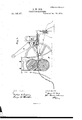
- Figure 1 is a side eleva- 4tlon of my improved machine.
- Fig. 2 is a plan of the same.
- Fig. 3 is a detached perspective view of the adjustable crank.
- Fig. 41 s a vertical mid-section of a modified form of a machine provided with my improvements.
- A is a stationary bed, to which are secured the side frames B B.
- C is a traveling bed, arranged to rest on the bed A. This bed is provided with a ratchet, a, on one edge, and the other edge may be graduated, as at b.
- D is a reciprocating cross-head, provided with jaws c c, ar ranged to embrace guides d d, secured to the side frames.
- E is a vertically-slotted frame, secured to the cross-head, in which plays the sliding block e, Fig. 3, of the adjustable crank F. This latter is tixed to a shaft, f, which has a long bearing at g in the side frame, which shaft bears on its outer end an operatlng-crank, Gr.
- a turn of the operating-crank G Will cause the cross-head D to travel back and forth on lts guides, its travel being regulated by means of the adjustable crank F, which has just been described.
- a bar bearing a serrated plaitingblade, H, arranged to rest upon the travelmg bed C, being held down by means of a suitable spring or springs, j 7', as shown.
- a rack, lc which engages a toothed segment, I.
- This segment turns on a stud or journal projecting from the side frame, and has an arm, l, which may be slotted, and to which is pivoted a pawl, J, the latter engaging the ratchet a on the traveling bed.
- L is a pressure-plate, slightly curved upward at the end, and entirely disconnected from the machine except in its functions, which will be explained further on.
- the function of the presser-plate is to flatten the folds of the plaits and break the creases, as well as to take each successive plait from the blade as made.
- the traveling bed C may be of any convenient length, and when pushed forward to its full length by the pawl, the latter can be lifted and the bed pushed back to the position it was in at starting without dis-arranging the goods being operated upon.
- the plaits are made Wide or narrow.
- the connection ofthe pawl J with the slotted arm l of the segment I so as to give more or less move ment to the pawl, the plaits may be made to overlap or to he separated by a space.
- An opening. q, in the blade H permits access to the cloth beneath, and by means of a button, r, the edge of the blade may be lifted at any time.
- roller or har o should be heavy enough to throw a moderate tension on the strip ot' passing goods, but not enough to impede the operation of the plaiting-blade.
- Fig. 4 I have shown the application of my adjustable crank to a plaiting-machine having rollers N N to receive and Hatten the plaits. These rollers may have a continuous rotary motion imparted by gears, as shown, or be driven intermittently by means of a pawl and ratchet.
- the adjustable crank for moving the cross-head consisting of the crank proper, F, having a dovetailed slot or groove in its face, the slide h, arranged to play in said groove, the sliding block e, and the set-screw i, all arranged substantially as set forth.
Landscapes
- Engineering & Computer Science (AREA)
- Textile Engineering (AREA)
- Treatment Of Fiber Materials (AREA)
Description
2 Sheets-Sheet 1.
J. W'. COX.
PLAITING-MACHINE. No.185,671 Patented Deo.26,1876.
l ||1.| mlmlrmxllmmmmmlpl/ 2 Sheets-Sheet 2.
J. w. cox.
PLAITING-MACHINE.
Pate
No..185,671. nm Dec. 25,1876.
A"UlvrTEn STATES PATENT CEErcE.
JAMES W. COX, OF PATERSON, NEW JERSEY.
' IMPROVEMENT IN PLAITING-MACHINES.
Specification forming part of Letters Patent No. 185,671, dated December 26, 1876; application filed September 18, 1876.
To all whom t 'may concern:
Be it known that I, J AMES W. Cox, of Paterson, in the county of Passaic and State of New Jersey, have invented certain Improvements in Plaiting-Machines, of which the following is a specification:
My improvements are especially adapted to machines intended for houshold use, and to be operated by hand 5 and the novel features and combinations will be fully described hereinafter.
In the drawings, Figure 1 is a side eleva- 4tlon of my improved machine. Fig. 2 is a plan of the same. Fig. 3 is a detached perspective view of the adjustable crank. Fig. 41s a vertical mid-section of a modified form of a machine provided with my improvements.
Referring to Figs. l and 2, Ais a stationary bed, to which are secured the side frames B B. C is a traveling bed, arranged to rest on the bed A. This bed is provided with a ratchet, a, on one edge, and the other edge may be graduated, as at b. D is a reciprocating cross-head, provided with jaws c c, ar ranged to embrace guides d d, secured to the side frames. E is a vertically-slotted frame, secured to the cross-head, in which plays the sliding block e, Fig. 3, of the adjustable crank F. This latter is tixed to a shaft, f, which has a long bearing at g in the side frame, which shaft bears on its outer end an operatlng-crank, Gr.
It will be observed (see Fig. 3) that the sliding block e is ixed toa slide, h, which plays in a dovetail slot, or its equivalent, in the face of the crank F. This device enables the operator to shorten or lengthen the throw of the crank at will by adjusting the slide h, which .may be xed in the desired position by means of the set-screw t'.
A turn of the operating-crank G Will cause the cross-head D to travel back and forth on lts guides, its travel being regulated by means of the adjustable crank F, which has just been described.
To the front edge of the cross-head is hinged a bar, bearing a serrated plaitingblade, H, arranged to rest upon the travelmg bed C, being held down by means of a suitable spring or springs, j 7', as shown.
0n the under side of the cross-head D, or on one of the jaws of the same, adjacent to the side frame B, is a rack, lc, which engages a toothed segment, I. This segment turns on a stud or journal projecting from the side frame, and has an arm, l, which may be slotted, and to which is pivoted a pawl, J, the latter engaging the ratchet a on the traveling bed.
As the cross-head D moves back and forth, the segment l is caused to oscillate. The pawlJ is advanced and retracted, and the bed G is moved forward intermittently. L is a pressure-plate, slightly curved upward at the end, and entirely disconnected from the machine except in its functions, which will be explained further on.
Across the back of the machine is fixed a rounded cross-bar, m, bearing two adjustable guides, n n. On this cross-bar rests loosely a roller or bar, o, its ends playing in vertical grooves in the frame.
Having thus set forth the mechanical construction of the machine, l will now describe its mode of operation.
The crank F having been adjusted to the proper throw for the desired width of plait, the strip of cloth p is passed between the properly-adjusted guides n n under the roller o, and thence forward under the serrated edge of the plaiting-blade H, the bed O being, at starting, pushed back toward the right in the figures as far as it can be without disengaging the pawl. Now place the. pressureplate L on the end of the stripp, substantially as in the figures, resting one hand upon it, and then turn the crank G with the other hand, in either direction.
lf the blade H is at the forward end of its stroke, the first effect of the movement will beto draw it back over the strip p, which is clasped between the plate L and the bed C. As the backward movement of the blade El is taking place, the pawl J advances and pushes forward the bed C, carrying with it the cloth p, the plate L, and the hand of the operator resting thereon. The plaitngblade now in turn advances and the pawl retracts, leaving the bed G stationary for the time. The serrated edge ofthe blade, as it starts to advance, bites into the cloth in the usual manner, and
proceeds to push forward enough for the plait. At this moment the. plait L is slipped along b v the hand resting on it far enough to catch the fold of the plait .being pushed forward by the blade and nip it, so that the receding blade may not carry it back and thus undo its work. The graduations at b will assist the operator in moving the plate L just far enough to be most e'ective, and not too far.
The function of the presser-plate is to flatten the folds of the plaits and break the creases, as well as to take each successive plait from the blade as made.
The traveling bed C may be of any convenient length, and when pushed forward to its full length by the pawl, the latter can be lifted and the bed pushed back to the position it was in at starting without dis-arranging the goods being operated upon.
By adjusting the crank F long or short, the plaits are made Wide or narrow. By adjusting the connection ofthe pawl J with the slotted arm l of the segment I so as to give more or less move ment to the pawl, the plaits may be made to overlap or to he separated by a space. An opening. q, in the blade H permits access to the cloth beneath, and by means of a button, r, the edge of the blade may be lifted at any time.
The roller or har o should be heavy enough to throw a moderate tension on the strip ot' passing goods, but not enough to impede the operation of the plaiting-blade.
In Fig. 4 I have shown the application of my adjustable crank to a plaiting-machine having rollers N N to receive and Hatten the plaits. These rollers may have a continuous rotary motion imparted by gears, as shown, or be driven intermittently by means of a pawl and ratchet.
I am aware that in plaiting-machines the use of an adj nstable sliding block to' vary the throw of the operatingcrank is not new, and such I do not claim.
I claim- 1. In a plaitingmachine, the adjustable crank for moving the cross-head, consisting of the crank proper, F, having a dovetailed slot or groove in its face, the slide h, arranged to play in said groove, the sliding block e, and the set-screw i, all arranged substantially as set forth.
2. The combination of the segment I, having a slotted arm, l, with the pawl J and rack k, when all arranged substantially as set forth.
3. The combination, in a plaiting-machine, of the traveling bed C, having a ratchet, a, the pawl J, the segment I, having an arm, l, the rack k, and the reciprocating cross-head D, when all arranged substantially as set forth.-
4. The combination of the traveling bed C, having a ratchet, a, the pawl J, segment I, and rack lc, cross-head D, plaiting-blade H, and springs j j, or their equivalents, when all a1'- ranged to operate asand for the purposes set forth.
5. The combination of the traveling bedO,
having a ratchet, a, the presser-plate L, pawl J, segment I, and rack k, cross-head D, blade H, sprin gs j j, slotted frame E, crank F, shaft f, and crank G, when lall arranged substantially as herein set forth.
In witness whereof I have hereunto signed my name in the presence'of two subscribing witnesses.
JAMES W.' COX.
Witnesses:
HENRY CONNETT, ARTHUR C. FRASER.
Publications (1)
| Publication Number | Publication Date |
|---|---|
| US185671A true US185671A (en) | 1876-12-26 |
Family
ID=2255077
Family Applications (1)
| Application Number | Title | Priority Date | Filing Date |
|---|---|---|---|
| US185671D Expired - Lifetime US185671A (en) | Improvement in plaiting-machines |
Country Status (1)
| Country | Link |
|---|---|
| US (1) | US185671A (en) |
-
0
- US US185671D patent/US185671A/en not_active Expired - Lifetime
Similar Documents
| Publication | Publication Date | Title |
|---|---|---|
| US185671A (en) | Improvement in plaiting-machines | |
| US399987A (en) | Paper-folding machine | |
| US641333A (en) | Punching-machine for metal strips. | |
| US8372A (en) | Milton d | |
| US624014A (en) | The norris peters cd | |
| US704449A (en) | Projecting apparatus. | |
| US727304A (en) | Machine for folding fabrics. | |
| US492116A (en) | Cloth-folding machine | |
| US141405A (en) | Improvement in paper-folding machines | |
| US626490A (en) | emmerich | |
| US469502A (en) | greene | |
| US1021050A (en) | Printing-press. | |
| US659171A (en) | Plaiting-machine. | |
| US459374A (en) | Mechanism for feeding strips of stock material | |
| US408913A (en) | farmer | |
| US573552A (en) | Machine for inking printing-plates | |
| US309878A (en) | Theophil basmus | |
| US1119857A (en) | Sheet-feeding device. | |
| US1120983A (en) | Jogger for paper-folding machines. | |
| US640520A (en) | Raising-gig for woolen fabrics. | |
| US1260158A (en) | Stamping-machine. | |
| US736031A (en) | Machinery for folding paper or other fabrics. | |
| US690638A (en) | Sheet-delivery mechanism for printing-machines. | |
| US1428025A (en) | Back-bar transfer mechanism for smut-sheeting machines | |
| US712788A (en) | Fabric folding and trimming machine. |