US1856719A - Toy moving picture machine - Google Patents
Toy moving picture machine Download PDFInfo
- Publication number
- US1856719A US1856719A US544153A US54415331A US1856719A US 1856719 A US1856719 A US 1856719A US 544153 A US544153 A US 544153A US 54415331 A US54415331 A US 54415331A US 1856719 A US1856719 A US 1856719A
- Authority
- US
- United States
- Prior art keywords
- casing
- cover
- rollers
- toy
- moving picture
- Prior art date
- Legal status (The legal status is an assumption and is not a legal conclusion. Google has not performed a legal analysis and makes no representation as to the accuracy of the status listed.)
- Expired - Lifetime
Links
- 239000000463 material Substances 0.000 description 7
- 238000010276 construction Methods 0.000 description 3
- 239000002184 metal Substances 0.000 description 3
- 229920002160 Celluloid Polymers 0.000 description 2
- 238000005452 bending Methods 0.000 description 2
- 238000004519 manufacturing process Methods 0.000 description 2
- ATJFFYVFTNAWJD-UHFFFAOYSA-N Tin Chemical compound [Sn] ATJFFYVFTNAWJD-UHFFFAOYSA-N 0.000 description 1
Images
Classifications
-
- A—HUMAN NECESSITIES
- A63—SPORTS; GAMES; AMUSEMENTS
- A63H—TOYS, e.g. TOPS, DOLLS, HOOPS OR BUILDING BLOCKS
- A63H33/00—Other toys
- A63H33/22—Optical, colour, or shadow toys
-
- A—HUMAN NECESSITIES
- A63—SPORTS; GAMES; AMUSEMENTS
- A63H—TOYS, e.g. TOPS, DOLLS, HOOPS OR BUILDING BLOCKS
- A63H33/00—Other toys
- A63H33/30—Imitations of miscellaneous apparatus not otherwise provided for, e.g. telephones, weighing-machines, cash-registers
Definitions
- My invention relates to a class of toy picin one piece and shown developed as cut out ture machines which provides for the indiand stamped from a sheet of metal. rect viewing of the pictures carried by a film Fig. 7 is one of the two rollers, (which are I or strip. I duplicates) and its handle for operating 6
- the object of this invention is to provide a same.
- FIGs. 8 and 9 are side and end views of the practical by showing pictures clearly and of metal clip for attaching the film strip to a such size as to be satisfactory to view while so roller.
- 1 is the rectangular casing to be marketable in five and ten cent sizes open on the front, said opening closed by the for children and with extra strips of pictures cover 2.
- the casing 1 is stamped out of sinfor one cent each. gle piece of material as shown in Fig. 5 for With the foregoing and other objects in bending at right angles along the dotted lines view which will appear as the description 3 to form the rectangular shape as shown in 15 proceeds, the invention consists of certain F1gs. 1, 3 and 4:.
- the cover 2 is stamped out features of novelty in the construction, comof a single piece of materlal as shown in Fig.
- FIG. 1 picture machine showing the handles for op- The sides 10 and 11, the top 12 and the hotcrating same. tom of casing 1 can be fastened at the cor- Fig 2 how a front el vation of the maners, but are preferably left free, as the overhi lapping cover 2 holds the sides and top and 1 3 i a ti l l ti f th the bottom rests on a table in line with the chinshown in Fig 1 amil on a line 3 f extended horizontal portion of the cover 2 Fi 2 and showin a dot and dash line of when in si it from the ceniir of the picture on the 15 r Slots m Side and 16 correspondmg 40 fi Strip to the mirror toward the y of holes 1n side 11 to support and form Journals or bearin 's for the rollers 17.
- rollers 17 gfi g Whlch would be above the have a la rge portion on one end forming a b t 1 th 7 2 i 1
- Fig. 4 is a front elevation of the machine 055 18 0 Over ap e edge of er Wlen in place and a reduced portion or groove 19 4-) with the cover and IIllII'OI removed to show next to Said boss 18 to form a bearing and the h P hold said roller 17 in place and prevent end the caslhg of the mahhlhe Whlch 15 motion. From the groove 19 the roller ta- 111 one P1606 and Shown developed as huh out pers to the opposite end.
- a handle 20 is inand stamped from a sheet of metal.
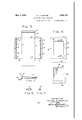
- FIG. 6 is the cover of the machine which is 17 to turn it.
- Each end of film strip 7 is fastened on to a roller 17 by means of a clip 21.
- Clip 21 is cut out on one side and has the same taper from end to end as roller 17, over which it is slipped endwise to bind the film strip 7 to said roller 17 as shown.
- Cover 2 is cut out to leave a si ht opening 22 which is covered by a transparent piece of material 23, as celluloid, to expose the pictures on the film strip 7.
- the sight op ning 22 being large and nearly as wide as the strip 7, the transparency 23 keeps the strip 7 smooth and prevents it from slipping into and binding in said opening 22.
- the celluloid 23 is fastened in the cover 2 by means of fingers 27 cut and bent from said cover 2.
- the mirror holding portion of cover 2 is slotted in two places as 25 and pressed out at 26. Reflecting material, as a bright piece of tin, is inserted in slots 25 to a pressed out stop 27 and forms a mirror 6. One edge of cover 2 forms a cap to hold the rollers 17 in the slots 15 when said cover 2 is on casing 1.
- the cover 2 is easily removed by springing in side 11 of casing 1 with the fingers away from cover 2.
- a new film strip is then substituted for the old by lifting the handle end of rollers 17 and withdrawing said rollers 17 from the holes 16 and clipping on a new film with clips 21.
- the film strip 7 is first in position wound on the lower roller as shown in Fig. 3 and rolled on to the upper roller by turning said upper roller in the direction of the arrow shown in Fig. 1,
- the lower handle is turned in the direction of the arrow for said lower roller in Fig. 1.
- a toy picture machine including a rectangular casing open on the front, an upper and a lower tapered roller journalled in said casing by means of holes in one side of said casing and slots in the opposite side of said casing, a film strip fastened at its ends to said tapered rollers, tapered clips to fasten said strip to said tapered rollers, a cover for the front opening of said casing to hold said rollers in said slots and having a sight opening for said film strip, a transparency for covering said sight opening and a mirror external to and in front of said casing, said mirror mounted in a portion of said cover extending away from the bottom of said cover.
- a toy picture machine including a rectangular casing having a back, two sides, top and bottom formed of a single piece of material, beading on the sides and top as stops for a cover, a cover formed of a single piece of material for the open front of said casing and having a sight opening therethrough, a film strip in said casing, two rollers in said casing, one above and one below said sight opening for holding and exposing said film strip through said sight opening, said rollers journalled in the sides of said casing by means of holes in one side and slots in the opposite side, a mirror and a support for said mirror formed from said cover and extending away from and in front of said cover.
- a toy picture machine including a rectangular casing formed of a single piece of material, the sides, top and bottom attached to and bent at right angles thereto, a cover formed of a single piece of material for the front of said casing and having a sight opening therethrough, a film strip in said casing to be exposed through said cover sight opening, an
- a toy picture machine incl uding 1 rectangular casing open on the front, an upper and a lower roller opposite the sight opening,
- rollers grooved on one end for bearing in slots in one side of said casing. and tapering to the opposite end for hearing in holes in the opposite side of said casing, a film strii in said casing, tapered clips to fasten sai film stri to said rollers, a cover for the front of said casing and having a top and sides overlapping said casing, detents on the sides of said cover and corresponding detents on the sides of said casing, a sight opening through said cover to expose said film strip, a transparency covering said sight opening, said cover extendin from the bottom thereof away from said casing and in an upward direction at an angle and a mirror mounted in said upward cover extension and opposite the center of said sight opening.
Landscapes
- Toys (AREA)
Description
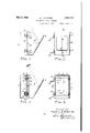
y 3, 1932- M. J. M INTYRE TOY MOVING PICTURE MACHINE 2 Sheets Sfieet 1 Filed June 13, 1931 FIG. 4.
INVENTOR M ICHAEL J. MQINTYRE y 1932- M. J. MCINTYRE 1,856,719
TOY MOVING PICTURE MACHINE Filed June 15, 1931 2 Sheets-Sheet 2 L. /I6 i 24 I I /I3 0: /I4
27 g 25 WWII],
FIG. 2
1:16.63- FIG. 9.
. INVENTOR Mucmxn. c]. M INTYRE BY -Q TORNEY Patented May 3, 1932 UNITED STATES PATENT OFFICE MICHAEL J. MCINTYBE, OF EDEN, NEW YORK TOY MOVING PICTURE MACHINE Application filed June 13, 1931. Serial No. 544,153.
My invention relates to a class of toy picin one piece and shown developed as cut out ture machines which provides for the indiand stamped from a sheet of metal. rect viewing of the pictures carried by a film Fig. 7 is one of the two rollers, (which are I or strip. I duplicates) and its handle for operating 6 The object of this invention is to provide a same.
moving picture toy which will be efficient and Figs. 8 and 9 are side and end views of the practical by showing pictures clearly and of metal clip for attaching the film strip to a such size as to be satisfactory to view while so roller.
-; simple and inexpensive in construction as In the figures, 1 is the rectangular casing to be marketable in five and ten cent sizes open on the front, said opening closed by the for children and with extra strips of pictures cover 2. The casing 1 is stamped out of sinfor one cent each. gle piece of material as shown in Fig. 5 for With the foregoing and other objects in bending at right angles along the dotted lines view which will appear as the description 3 to form the rectangular shape as shown in 15 proceeds, the invention consists of certain F1gs. 1, 3 and 4:. The cover 2 is stamped out features of novelty in the construction, comof a single piece of materlal as shown in Fig. bination and arrangement of parts by which 6 for bending at right angles along the dotthe said objects are attained, the invention ted llnes to form a cover for casing 1, and being more particularly pointed out in the for bendmg at an obtuse angle on dotted 20 1 m line 5 to take the shape shown in Figs. 1 and It is understood that various changes may 3 for holding a mirror at the proper angle be made in the construction and arrangement and away from said cas ng 1 so the observer of parts without departing from the spirit or can see the picture reflected from the film sacrificing any of the advantages of the instrip 7 as lndlcated by the dot and dash line #5 vention as set forth in the appended claims. 8. On casing 1 a head 9 is formed (Fig. 5)
Referring to the drawings accompanying on the sides 10 and 11 and the top 12 to and forming a part of this specification, stiffen them and as a stop for the cover 2 wherein like symbols refer to like or correwhen acting in COIlJllIlCtlOn with the detents sponding parts throughout the several or pressed out portions 13 of said casing 1 30 views: and the corresponding detents or pressed out Figure 1 is a side elevation of my moving portions 1 1 of said cover 2.
picture machine showing the handles for op- The sides 10 and 11, the top 12 and the hotcrating same. tom of casing 1 can be fastened at the cor- Fig 2 how a front el vation of the maners, but are preferably left free, as the overhi lapping cover 2 holds the sides and top and 1 3 i a ti l l ti f th the bottom rests on a table in line with the chinshown in Fig 1 amil on a line 3 f extended horizontal portion of the cover 2 Fi 2 and showin a dot and dash line of when in si it from the ceniir of the picture on the 15 r Slots m Side and 16 correspondmg 40 fi Strip to the mirror toward the y of holes 1n side 11 to support and form Journals or bearin 's for the rollers 17. The rollers 17 gfi g Whlch would be above the have a la rge portion on one end forming a b t 1 th 7 2 i 1 Fig. 4 is a front elevation of the machine 055 18 0 Over ap e edge of er Wlen in place and a reduced portion or groove 19 4-) with the cover and IIllII'OI removed to show next to Said boss 18 to form a bearing and the h P hold said roller 17 in place and prevent end the caslhg of the mahhlhe Whlch 15 motion. From the groove 19 the roller ta- 111 one P1606 and Shown developed as huh out pers to the opposite end. A handle 20 is inand stamped from a sheet of metal. serted and fastened into the boss end of roller Fig. 6 is the cover of the machine which is 17 to turn it. Each end of film strip 7 is fastened on to a roller 17 by means of a clip 21. Clip 21 is cut out on one side and has the same taper from end to end as roller 17, over which it is slipped endwise to bind the film strip 7 to said roller 17 as shown.
The mirror holding portion of cover 2 is slotted in two places as 25 and pressed out at 26. Reflecting material, as a bright piece of tin, is inserted in slots 25 to a pressed out stop 27 and forms a mirror 6. One edge of cover 2 forms a cap to hold the rollers 17 in the slots 15 when said cover 2 is on casing 1.
The cover 2 is easily removed by springing in side 11 of casing 1 with the fingers away from cover 2. A new film strip is then substituted for the old by lifting the handle end of rollers 17 and withdrawing said rollers 17 from the holes 16 and clipping on a new film with clips 21.
In the operation of the machine, the film strip 7 is first in position wound on the lower roller as shown in Fig. 3 and rolled on to the upper roller by turning said upper roller in the direction of the arrow shown in Fig. 1, To return the strip 7 on to the lower roller, the lower handle is turned in the direction of the arrow for said lower roller in Fig. 1.
Having thus described my invention, I claim as new and desire to secure by Letters Patent:
1. A toy picture machine including a rectangular casing open on the front, an upper and a lower tapered roller journalled in said casing by means of holes in one side of said casing and slots in the opposite side of said casing, a film strip fastened at its ends to said tapered rollers, tapered clips to fasten said strip to said tapered rollers, a cover for the front opening of said casing to hold said rollers in said slots and having a sight opening for said film strip, a transparency for covering said sight opening and a mirror external to and in front of said casing, said mirror mounted in a portion of said cover extending away from the bottom of said cover.
2. As a product of manufacture, a toy picture machine including a rectangular casing having a back, two sides, top and bottom formed of a single piece of material, beading on the sides and top as stops for a cover, a cover formed of a single piece of material for the open front of said casing and having a sight opening therethrough, a film strip in said casing, two rollers in said casing, one above and one below said sight opening for holding and exposing said film strip through said sight opening, said rollers journalled in the sides of said casing by means of holes in one side and slots in the opposite side, a mirror and a support for said mirror formed from said cover and extending away from and in front of said cover.
3. As a product of manufacture, a toy picture machine including a rectangular casing formed of a single piece of material, the sides, top and bottom attached to and bent at right angles thereto, a cover formed of a single piece of material for the front of said casing and having a sight opening therethrough, a film strip in said casing to be exposed through said cover sight opening, an
upper and a lower roller with handles for holding and moving said film across said sight opening, each of said rollers journalled in said casing on one side by means of slots, said cover having sides to overlap said casing, attach thereto and hold said rollers in said slots, and a bottom portion extending horizontally away from said casing and terminating in an upwardly extendin portion in front of said sight opening and a mirror attached to said upwardly extending portion and opposite said sight openin 4. A toy picture machine incl uding :1 rectangular casing open on the front, an upper and a lower roller opposite the sight opening,
said rollers grooved on one end for bearing in slots in one side of said casing. and tapering to the opposite end for hearing in holes in the opposite side of said casing, a film strii in said casing, tapered clips to fasten sai film stri to said rollers, a cover for the front of said casing and having a top and sides overlapping said casing, detents on the sides of said cover and corresponding detents on the sides of said casing, a sight opening through said cover to expose said film strip, a transparency covering said sight opening, said cover extendin from the bottom thereof away from said casing and in an upward direction at an angle and a mirror mounted in said upward cover extension and opposite the center of said sight opening.
In testimony whereof I afiix In si nature.
MICHAEL J. M01 1* RE.
Priority Applications (1)
| Application Number | Priority Date | Filing Date | Title |
|---|---|---|---|
| US544153A US1856719A (en) | 1931-06-13 | 1931-06-13 | Toy moving picture machine |
Applications Claiming Priority (1)
| Application Number | Priority Date | Filing Date | Title |
|---|---|---|---|
| US544153A US1856719A (en) | 1931-06-13 | 1931-06-13 | Toy moving picture machine |
Publications (1)
| Publication Number | Publication Date |
|---|---|
| US1856719A true US1856719A (en) | 1932-05-03 |
Family
ID=24170965
Family Applications (1)
| Application Number | Title | Priority Date | Filing Date |
|---|---|---|---|
| US544153A Expired - Lifetime US1856719A (en) | 1931-06-13 | 1931-06-13 | Toy moving picture machine |
Country Status (1)
| Country | Link |
|---|---|
| US (1) | US1856719A (en) |
Cited By (1)
| Publication number | Priority date | Publication date | Assignee | Title |
|---|---|---|---|---|
| USD872808S1 (en) * | 2017-12-15 | 2020-01-14 | NJN Enterprises | Book prop |
-
1931
- 1931-06-13 US US544153A patent/US1856719A/en not_active Expired - Lifetime
Cited By (1)
| Publication number | Priority date | Publication date | Assignee | Title |
|---|---|---|---|---|
| USD872808S1 (en) * | 2017-12-15 | 2020-01-14 | NJN Enterprises | Book prop |
Similar Documents
| Publication | Publication Date | Title |
|---|---|---|
| US2850294A (en) | Picture album | |
| US2160724A (en) | Display device | |
| US2112583A (en) | Ornamental display device | |
| US1980453A (en) | Ornamental display device | |
| US1992487A (en) | Combined book-end and picture frame | |
| US2093160A (en) | Sample holder and easel therefor | |
| US1856719A (en) | Toy moving picture machine | |
| US2334483A (en) | Folding stereoscope | |
| US1914068A (en) | Picture stand | |
| US1964879A (en) | Picture display device | |
| US1615324A (en) | Strap-watch display device | |
| US1729480A (en) | Album | |
| US2227898A (en) | Display device | |
| US2122804A (en) | Motion picture viewer | |
| US1999133A (en) | Film exhibitor | |
| US2165122A (en) | Cabinet | |
| US2177914A (en) | Sample holder | |
| US2120456A (en) | Ornamental device | |
| US2607263A (en) | Animated picture viewer and pictures in book form | |
| US2764161A (en) | Label holder for ledger book | |
| US1463326A (en) | Display sign | |
| US949328A (en) | Display-frame for cards. | |
| US1752952A (en) | Display device | |
| US2807199A (en) | Multiple film strip contacting printing device | |
| US1252918A (en) | Picture-frame. |