US1856718A - Elevator door operating mechanism - Google Patents
Elevator door operating mechanism Download PDFInfo
- Publication number
- US1856718A US1856718A US218290A US21829027A US1856718A US 1856718 A US1856718 A US 1856718A US 218290 A US218290 A US 218290A US 21829027 A US21829027 A US 21829027A US 1856718 A US1856718 A US 1856718A
- Authority
- US
- United States
- Prior art keywords
- door
- car
- driving element
- movement
- lever
- Prior art date
- Legal status (The legal status is an assumption and is not a legal conclusion. Google has not performed a legal analysis and makes no representation as to the accuracy of the status listed.)
- Expired - Lifetime
Links
Images


Classifications
-
- B—PERFORMING OPERATIONS; TRANSPORTING
- B66—HOISTING; LIFTING; HAULING
- B66B—ELEVATORS; ESCALATORS OR MOVING WALKWAYS
- B66B13/00—Doors, gates, or other apparatus controlling access to, or exit from, cages or lift well landings
- B66B13/02—Door or gate operation
- B66B13/06—Door or gate operation of sliding doors
- B66B13/08—Door or gate operation of sliding doors guided for horizontal movement
Definitions
- This invention relates to improvements in apparatus adapted for use in the opening and closing of elevator doors.
- It is an object of the invention to provide an improved elevator door operating apparatus comprising door openin and closing mechanism at various landings of an elevator shaft and a single motive device on the car by which the mechanisms at the landings may be operated, the mechanism at each landing being preferably of the toggle type and including means tending to close the door when open, as well as a directly connected cushioning device to gradually bring the door to rest, said cushioning device being preferably effective at the end of the opening movement of the door as well as at'the end of the closing movement.
- Another object of the invention is to produce an improved elevator door operating apparatus of the character described, such as will permit the doors at the various floors of the elevator shaft to be more speedily opened and closed with a minimum amount of jar and noise and with a minimum amount of wear and tear, due to the elimination of all unnecessary backlash or lost motion between the parts of the mechanism, and particularly between the cushionin device and the parts of the apparatus directly connected with the doors.
- the invention also includes among its important features a novel type of motive device on the car, having means whereby its driving element may be yieldingly held in a normal position by means which may be overcome during the initial part of the move* ment of the driving element when the motive device is energized to elfect a door opening operation of one of the mechanisms at a landing.
- a further object of the invention is to provi de a door operating apparatus of the character described, having a. disabling mechanism connected with the motive device on the car by which the car operating mechanism may be rendered impotent on the initial movement of the motive device when energized to effect a door opening operation of a mechanism at a landing, and whereby the car operating mechanism may be restored to its normal effective condition at the end of the return motion of the motive device to its normal position.
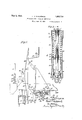
- Figure 1 is a view in elevation, as seen from within the elevator shaft, of a door, specificaliy disclosed as a double door, and the door operating mechanism therefor, the same being representative of the doors and operating mechanisms which should be duplicated at each landing of the shaft, the doors being indicated as being closed.
- Fig. 2 is a similar view of a like door and its door operating mechanism, the doors being indicated as having been opened.
- Fig. 3 is a longitudinal sectional view of a combined door closing and cushioning device included as a partof the door operating mechanism illustrated in Figs. 1 and 2.
- Fig. 4 is a view in elevation of a portion of an elevator car and a motive device carried thereby, whereby the mechanisms illustrated in Figs. 1 and 2 at the various landings of the shaft may be operated.
- the car is indicated as having been brought to a level with one of the landings, thereby establishing a cooperative relation between the motive device on the car and the door operating mechanism at the landing.
- Fig. 5 is a view similar to Fig. 4, the parts of the mechanism being represented as hav- 7 controller may be rendered impotent and re structure of the elevator shaft.
- Figs. 1 and 2 a type of door operating mechanism adapted for use as a part of the present invention, applied to a door (herein disclosed as a double door) comprising door sections 20,20, which may be mounted for sliding movement to open and closed positions with respect to a doorway in the elevator shaft by means or" hangers (not disclosed) of any appropriate character. These doors may be mounted in an overlapping relation so as to occupy sub stantially the space of a single door section when open. 1
- the door sections 20, 20 may be provided with an opening and closing mechanism of any appropriate character, herein disclosed as one of a compound toggle type, adapted for the operation of said double door sections.
- This mechanism may comprise a lever 21 pivotally connected at 22 to a bracket or other suitable support 23, which may be secured to any appropriate part of the fixed
- the lever 21 may be pivoted, as at 24, to one end of a lever 25, said lever 25 being pivoted intermediate its ends to the door section 20, as at 26.
- the lever 25 may be pivoted at or near its opposite end, as at 27, to one end of a connecting bar 28 having its other end pivotally connected, as at 29, to the door section 20.
- one or" its elements may be provided with a portion 30 adapted to serve as a handle by which the toggle may be broken when it is desired to operate the mechanism by hand.
- a downward pull on the handle 30 will cause'the ends of the lever 25 andbar 28, which are connected at 27, to move downwardly, and will cause the ends of the levers 21 and 25, which are connected at 24, to move upwardly, whereby the door sections will be caused to move toward the cated in Fig. 2.
- toggle element 21 may be extended and provided with-a slotted portion adapted to receive the projecting element 31 and bring the parts to rest when the elements of the toggle are in alignment, as indicated in Fig. 1.
- the present invention includes apparatus comprising a single motive device located on and controllable from the elevator car, whereby door operating mechanisms of the above-described character at various landings of the shaft may be operated without resort to the use of the handle 30.
- the lever 21 may be provided with an arm 38,-to which may be pivotally connected, as at 34, one end of a connecting rod 85, the other end of which (see Fig. 4) may be piv otally connected, as at 36, to a connecting block 37, which, in turn, may be pivotally connected, as at 38, to one arm of a lever 39 pivotally connected, as at 40, to a bracket or other suitable support 41 fixedly secured to any appropriate part of the permanent structure of the elevator shaft.
- a roller 43 adapted to receive the thrustof a driving element of the motive device on the car, hereinafter to be described, when advanced to efiect a door opening operation of the mechanism on the landing.
- the lever 21 may be provided with a third arm 44, which may be pivotally connected, as at 45, with a connecting rod 46 of a door closing and cushioning device 47, said device, in turn, being pivotally connected, as at 48, to a bracket or other suitable support 49, which may be fixedly secured to any appropriate part of the shaft structure.
- a preferred form of door closing and cushioning device is illustrated in detail in Fig. 3, in which the two elements are combined and enclosed within a single cylinder 50 having a closed cap 51 at one end provided with an extension 52 to form a part of the piv otal connection 48, and a cap 53 at the opposite end having an opening 54 therein forming a guideway for the connecting rod 46.
- a spring 55 may be confined between the cap 53 of the cylinder 50 and a spider 56, which may surround the connecting rod 46, and held against axial displacement by means of a collar or other suitable obstructing element 57.
- theconnecting rod 46 is provided with a piston 58, which may be secured to its free end by means of a nut 59 ;or any other appropriate fastening device.
- the cylinder may :be mounted a secondary cylinder 60, having walls concentric with but separated from the walls of the cylinder 50.
- the cylinder 60 may be threaded into and closed at one end by a part of the cap 51, and may be closed at its opposite end by a cylinder head 61.
- the piston 58 should be of such diameter as to provide a mere, free working clearance between its outer surface and the inner surface of the cylinder 60.
- the cylinders 50and 60 be filled with any appropriate liquid, preferably one of 'a non-corrosive character and one having a relatively low freezing point.
- a graduated by-pass F about the piston may be provided in any suitable manner, as by means of graduated openings 62 in the walls of the cylinder 60, through which liquid may pass in either direction and be permitted to circulate during the movement of the piston.
- one opening 62 will be so disposed as to be immediately opened on the initial movement of the piston from its normal position, and the other openings will he graduated in size so that the means of communication through the wall of the cylinder 60 will be rapidly increased as the piston moves away from the end of the cylinder. ()n the return of the piston, the larger opening in the cylinder wall will first be closed, after which the openings of smaller and smaller diameter will be successively closed, thus variably reducing the means of communication through the cylinder wall as the piston approaches the end of the cylinder.
- a checking device of the above-described character may be provided with graduated openings in the cylinder wall at either end of the cylinder 60 so as to check the movement of the door and gradually bring it to rest at the end of either a door opening or a door closing operation.
- openings will be provided at both ends of the cylinder 60 as indicated in Fig. 3, in which the second set of openings are-designated 63.
- the end of the cylinder 60 opposite that provided with graduated openings should be left open.
- the piston may, if :desired, be provided with a packing ring 64, of any suitable character andthe length of the cylinder 60 should be such as to lPTO-V-lClG for the .requisite degree 0f movement of the piston to permit the toggle mechanism to move the doors from closed to open position, :and vice versa.
- the escape of liquid from the cylinder ;50 where the connecting rod 46 enters the cap or head 53 may be prevented in any suitable manner, as by packing 65, which maybe confined within a stulhng box by .a gland 6.5.
- the adjustment of the spring may be effected in any appropriate manner, .as by rotation of the head or cap 53, which has :a .thneadecl connection proaches either :end of the cylinder applies a gradually increasing checking resistance adapted to bring the doors to rest with a minimum degree of jar and noise.
- This smooth and quiet operation of thedoor door operating mechanism is facilitated by use of the toggle connection illustrated as a 3 art of the preferred form of the invention, in that it provides for a gradually retarded door movement compared with the movement of the toggle mechanism :as the door elements approach their closed positions.
- the toggle may also be so adjusted with respect to the doors as to gradually bring them to rest before the door element 20 comes into contact with the jam-b :of the door, thereby avoiding an y shock .at the end of the closing operation.
- the single vmotive device on the car by which the door operating mechanisms at the various landings may be operated is illustrated in its preferred form in Figs. l and 5.
- This motive device may comprise a driving element 66, which may be so mounted any appropriate means that it may be advanced against the roller 43 and thereby rock the lever 39 to a sufficient extent to effect the desired opening operation of the toggle 'mech anism.
- One form of mounting for the driving element 66, herein illustrated, comprises a pair of arms 67, 67, each pivoted one end as at '68, 69, to the driving element, and each pivoted at its opposite end as at 70, 71, to a bracket 72, or other suitable support, which may be fixed :to any appropriate part of the elevator car 73.
- the arm I67 preferably forms one part of a lever 74, having another arm pivotally connected, as at 76, to a connectingrod 77, which, in turn, may be pivotally connected, as at 78, to one end of a piston rod 79 secured at its other end to a piston 80 mounted for reciprocation within a cylinder 81.
- the motive device comprising the cylinder 81 and its piston 80 may be energized by the admission of air under pressure between the piston 80 and the cylinder head 82, thereby causing the piston to advance and effect a rocking of the lever 74, which will, in turn, impart an advance movement to the driving element 66.
- the admission of'air to the cylinder 81 may be controlled in any suitable manner, as by means of a two-way valve 83, which may be connected between the cylinder 81 and a flexible admission pipe 84 leading to any appropriate source of supply in the elevator shaft.
- The'two-way valve 83 may be provided with ports 85, 86, which may be so positioned as to connect the end of the cylinder with atmosphere through a port 87 in the valve casing, as indicated in Fig. 4, or which may be turned to another position by the .evcr 88, to cause the port 85 to connect the end of the cylinder with the admission pipe or tube 84.
- Another vent 87 may be provided in the forward cylinder head, whereby the air in the cylinder may be eX- hausted during the forward movement of the piston, and through which air may enter the cylinder as the piston is returned to its normal position.
- the control of the valve 83 may be effected by any appropriate means, a simple form of mechanism adapted for such purpose being indicated in Fig. 6.
- This mechanism comprises a hand-lever 89, which may be pivoted as at 90 to some suitable part of the elevator car 73.
- One end of the lever 89 may be pivotally connected, as at 91, to a connecting rod 92, which, in turn, may be pivotally connected with the free end 93 of the lever 88.
- the lever 89 may be provided with the usual sliding lock 94, mounted for endwise move ment in a guideway 95 carried by the lever 89 and adapted to be withdrawn from its locking engagement with a slotted portion 96 in a support 97 by means of an auxiliary lever 98 pivotally connected to the handle of the lever 89.
- a spring (not shown) may be provided, normally tending to move the locking element 94 into engagement with. the notch 96.
- the upper end of the lever 89 On releasing the lock 94, the upper end of the lever 89 may be moved to the left as viewed in Fig.
- a second notch 96 may be provided in the support 97 to be engaged by the locking element 94 when the lever has been moved to a position such as to energize the motive device.
- the door may be released by returning the lever 89 to the position indicated in full lines in Fig. 6, thereby connecting the piston 81 with atmosphere and rendering the motor passage, after which the spring 55 (Fig. 3) of the door operating mechanism may cause the doors and connected door operating mechanism tobe returned to their normal positions, during which closing operation the roller 43 on the lever 39 will partially restore the driving element 66 to its normal position.
- this invention provides means whereby a further return move ment may be imparted to the driving element 60 so as to leave a clear space between the roller and the face of the driving element.
- a roller 107 On the lever 104 may be journaled a roller 107 adapted to serve as a follower with respect to a cam 108 secured to an extension of the shaft forming part of the pivotal connection of the lever 74.
- the cam 108 may have a depression 109 in its working face so positioned as to receive the follower 107 when the driving element is in its normal position clear of the roller 43, whereby the cam and its follower, which are constantly urged one towards the other by the spring 99, may serve as a holding means to yieldingly retain the driving element 66 in such normal position.
- the form of the working surface of the cam may be such that the motive element 80, 81, when energized, may overcome the holding effect of the cam and follower and cause the follower to be moved out of the depression and roll along the uniform surface 110 of the cam, during which movement the spring 99 will be held compressed but its effect upon the cam and follower will be passive, thereby opposing no material resistance to the further operation of the door operating mechanism by the motive device 80, 81. Due to the uniform curvature of the surface 110 of the cam, no material opposition will be set up by the spring 99 and associated parts to the return movement of the driving element by the spring 55 (Fig. 3) of the door operating mechanism.
- the depression 109 of the cam 108 is so positioned with respect to the follower that the latter will slightly enter the depression before the roller 43 has been fully returned to its normal position. The completion of the movement of the follower into the depression in the cam as a result of the expansion of the spring 99 will therefore effect a further movement of the driving element 66 through the cam and connecting elements, thus separating the driving element from the roller 43 and providing the desired working clearance.
- the driving element 66 shall be advanced only after the car has been brought to rest, or substantially at rest, at one of the landings in the elevator shaft.
- the element 66 is gradually flared upwardly and downwardly from its central portion in a direction away from the roller 43 so as to provide cam-like elements 111, 112, of gradua1 slope adapted to engage and 'ently move the roller, thereby effecting a door opening operation of the mechanism at a landing as the car approaches the same.
- the car operating mechanism may be rendered impotent by the motive device when it is energized to effect a door opening operation of the door at any landing, and may be restored to its normal effective condition after the doors have been closed.
- the disabling of the car operating mechanism is indicated as being effected by opening switches in the electric leads by which an electric controller in the car is connected with the controlling switches of the motor (not shown) by which the car is moved in the shaft.
- Fig. '7 is a conventional representation of an electric controller 113, comprising a conductive segment 114 which may be moved by an operating arm 115 and thereby caused to close either of two circuits, one of which normally conditions the operating mechanism of the car for ascent and the other of which conditions it for descent.
- the operating arm 115 By movement of the operating arm 115 in a clockwise direction the circuit may be closed at the controller from conductor 116 to conductor 11'? at the contacts 118, and unless this circuit is opened at another point by the disabling means, hereinafter to be described, the car will be caused to move in one direction by its operating mechanism.
- the arm 115 On movement of the arm 115 in a be connected with conductor 120 at the contacts 121, and unless the circuit is opened by the disabling means the car will be moved in the opposite direction.
- the disabling device whereby the controller 113 and other parts of the car operating mechanism may be rendered impotent by the motive device which operates the door opening and closing mechanisms, as herein disclosed, comprises a double pole switch 122, comprising connectors 123, 124, pivotally mounted w tin a housing 125, by which,
- conductor 117 when in closed position, conductor 117 may be connected with conductor 126, and by which conductor 120 may be connected with conductor 127.
- These connectors 123, 124 may be mutually connected by an insulated bar 128, having a pin-and-slot connection or other appropriate coupling with one arm of a lever 129, pivotally mounted within the housat 130, the other arm of said lever being pivotally connected, as at 131, to one end of a connecting rod 132, the other end of which may be pivotally connected, as at 133, with the end of the lever 104.
- the connecting elements of the disabling device When the parts of the motive device are in the positions indicated in Fig. 4, the connecting elements of the disabling device will bein their circuit-closing positions, as indicated in broken lines in Fig. 7, thus permitting the controller of the car operating mechanism to function in its normal manner and serve as a means whereby the car may be caused to move either up or down in the elevator shaft at will.
- the disabling device When the parts of the motive device are moved to the positions indicated in Fig. 5, the disabling device is moved to the position indicated in full lines in Fig. 7 thereby opening the leads 116, 117, 126, and 119, 120, 127, from the controller to the motor-controlling switches, and thus rendering the car operating mechanism impotent.
- the disabling mechanism will be rendered effective to open the controller circuits on the initial movement of the motive device 80, 81, to take up the clearance between the driving element 66 and the roller 43, thereby rendering the car operating mechanism impotent before any substantial opening of the door at the landing at which the car is stationed.
- the disabling mechanism will not close the controller circuits and thereby restore the car operating mechanism to its normal condition until the follower 107 is moved into the depression 109 in the cam 108, which takes place after the door has been substantially closed, the closing of the circuits by the disabling mechanism being effectedby the movement imparted to the driving element by the spring 99 as the follower is forced into the depression in the cam to complete the return movement of the driving element to a position clear of the roller 43.
- the representations of the motive device 80, 81 (Fig. 4), its controlling mechanism (Fig. 6), and the controller and disabling device (Fig. 7) are intended to be conventional only.
- the driving element 66 may be advanced by any appropriate motive device other than the fluid pressure motor illustrated in Fig. 5, and may be controlled by any suitable means including, if desired, a controlling means which shall be efiective only when the car has been brought to rest at one of the landings of the shaft.
- a controlling means which shall be efiective only when the car has been brought to rest at one of the landings of the shaft.
- Such specific controlling means for the motive device on the car constitutes no part of the invention herein disclosed and claimed, and is therefore neither illustrated nor described.
- the disabling device may be modified to conform with the particular type of car operating mechanism and controller which may be used as a part of the elevator plant to which the invention is applied.
- each door operating mechanism is directly connected with its door closing means and with its cushioning means, thereby eliminating lost motion and backlash between said directly connected elements, as a result-of which the doors may be rapidly operated with a minimum degree of noise.
- the operation of the disabling device during the initial and final movements of the driving element while free from contact with the roller 43 prevents the accidental or unintended opening of the door without bringing thecar to rest, and also prevents the acci dental or unintended movement of the car away from the landing until the door has been closed or nearly so.
- the invention lends itself readily to the usual emergency door opening and car releasing means.
- the doors may be readily opened from outside the shaft by the insertion of a thin rod or bar through a narrow slot 134:, which may be used as a lever to slightly depress the connecting arm 23 and pivoted end of the lever 25, thereby breaking the toggle and permitting the door to be opened.
- the emergency release of the car when the doors are open, may be efiected by withdrawing the driving element manu- (Figs. 4 and 5), one end of which may be connected to the driving element and the other end of which may be connected to a ring or hook enclosed within a housing (not shown) having a glass face which may be broken to rein der the ring or hook accessible.
- WVhat is claimed is:
- said di device consisting of a mechanism comprising a cam and follower and a spring to urge one of said parts towards the other, said cam and follower being so connected between said motor and the controlling mechanism of the car as to be subjected to relative movement dependent on the movement of the driving element, said cam having adepression into which said follower may be forced by said spring and from which it may be displaced by said motor, the relative movementthus produced between said cam and follower serving as the means whereby said disabling device may vary the condition of the car controlling mechanism, the form of said cam and the location of the depression therein being such that the disabling device may render said car controlling mechanism impotent as a result of the displacement of said follower from said depression on the initial advance movement of said driving element to effect a door opening operation of a mechanism at a landing, remain passive during the remainder of its advance movement and all but asmall portion of its return movement, and restore said car controlling mechanism to normal eifective condition at the end of the return movement of said driving element on the return of said follower into the
- the combination, with the doors atvarious landings of an elevator shaft and an elevator car, of door opening and closing mechanisms at said landings including means tending to close said doors when open, a driving element on said car so positioned as to be brought into cooperative relation with the respective door operating mechanisms on movement of said car to the various landings, a motor on said car having controlling means therefor by which it may be energized and ole-energized at will, said motor, when energized, serving as means whereby said driving element may be advanced and thereby caused to effect a door opening operation of the mechanism at any landing at which the car may have been brought to rest, the door closing means of said mechanism serving as means to impart a partia return movement to said driving element after the motor has been de-energized, and an auxiliary motive device having an operative connection with said driving element through which an additional return movement may be imparted thereto after the completion of the part of its return movement imparted by the door operating mechanism, whereby said driving element may be moved to a position affording a free working clearance between its working face and
- the invention of claim 6 having, as its auxiliary motive device, a cam and follower and a spring by which said cam and follower may be constantly urged one towards the other, said cam and follower being so connected between the spring and the driving element as to be subjected to relative movement dependent upon the movement of the latter, said cam having a depression into which the follower may be forced by the spring, thereby producing the relative motion necessary to impart the final return movement to the driving element, the form of said cam and the location of the depression therein being such as to cause said auxiliary motive device to be primed during the initial movement of said driving element by the motor to.
Landscapes
- Elevator Door Apparatuses (AREA)
Description
ELEVATOR DOOR OPERATING MECHANISM Filed Sept-8, 1927 5 Sheets-Sheet l By Attorneys,
JAM/W7 May 3, 1932. H. v. M CORMICK ELEVATOR DOOR OPERATING MECHANISM Filed Sept. 8, 1927 3 Sheets-Sheet INVENT0R= Lmmrm,
May 3, 1932. H. v. M CORMICK 1,856,718
ELEVA'I OR DOOR OPERATING MECHANISM Filed Sept. 8, 1927 3 Sheets-Sheet 3 un 13! 0 0 7.9 as ($1 ENVENTOR By Attorneys,
Patented May 3, 1932 r ore mamm' EAnonn v. MCCORMICK, or LONG BEACH, NEW Yonnassienon, BY MESNE assreiv-f MENTS, TO wnsrmenonsn ELECTRIC ELEVATOR COMPANY, or CHICAGO, ILLINOIS,
A CORFOBATIQN F ILLENQIS ELEVATOR 1300B OPERATING MECHANESM Application filed September a, 1927. Serial No. 218,290.
This invention relates to improvements in apparatus adapted for use in the opening and closing of elevator doors.
It is an object of the invention to provide an improved elevator door operating apparatus comprising door openin and closing mechanism at various landings of an elevator shaft and a single motive device on the car by which the mechanisms at the landings may be operated, the mechanism at each landing being preferably of the toggle type and including means tending to close the door when open, as well as a directly connected cushioning device to gradually bring the door to rest, said cushioning device being preferably effective at the end of the opening movement of the door as well as at'the end of the closing movement.
Another object of the invention is to produce an improved elevator door operating apparatus of the character described, such as will permit the doors at the various floors of the elevator shaft to be more speedily opened and closed with a minimum amount of jar and noise and with a minimum amount of wear and tear, due to the elimination of all unnecessary backlash or lost motion between the parts of the mechanism, and particularly between the cushionin device and the parts of the apparatus directly connected with the doors.
It is a further object of the invention to produce a door operating apparatus of the above-described character in which the opening and closing mechanisms at the various landings, preferably of the toggle type, shall be connected with the doors substantially mid way between their tops and bottoms, thereby eliminating a? tendency of the doors to clamp or bind with parts of the structure by and within which they are mounted during their opening and closing movements.
It is also an important feature of the in vention to provide means whereby the part of the mechanism on the car which cooperates with the door operating mechanisms atthe landings may be moved away from the opposed portions of the latter in order to provide a free working clearance and prevent accidental engagements of the parts during the travel of the car.
The invention also includes among its important features a novel type of motive device on the car, having means whereby its driving element may be yieldingly held in a normal position by means which may be overcome during the initial part of the move* ment of the driving element when the motive device is energized to elfect a door opening operation of one of the mechanisms at a landing.
A further object of the invention is to provi de a door operating apparatus of the character described, having a. disabling mechanism connected with the motive device on the car by which the car operating mechanism may be rendered impotent on the initial movement of the motive device when energized to effect a door opening operation of a mechanism at a landing, and whereby the car operating mechanism may be restored to its normal effective condition at the end of the return motion of the motive device to its normal position.
In the drawings illustrating the preferred form of the invention Figure 1 is a view in elevation, as seen from within the elevator shaft, of a door, specificaliy disclosed as a double door, and the door operating mechanism therefor, the same being representative of the doors and operating mechanisms which should be duplicated at each landing of the shaft, the doors being indicated as being closed.
Fig. 2 is a similar view of a like door and its door operating mechanism, the doors being indicated as having been opened.
Fig. 3 is a longitudinal sectional view of a combined door closing and cushioning device included as a partof the door operating mechanism illustrated in Figs. 1 and 2.
Fig. 4; is a view in elevation of a portion of an elevator car and a motive device carried thereby, whereby the mechanisms illustrated in Figs. 1 and 2 at the various landings of the shaft may be operated. Inthis figure, drawn to a larger scale than that-of 1 and 2, and represented as being viewed in a direction at right angles to that of the viewpoint of Figs. 1 and 2, the car is indicated as having been brought to a level with one of the landings, thereby establishing a cooperative relation between the motive device on the car and the door operating mechanism at the landing.
Fig. 5 is a view similar to Fig. 4, the parts of the mechanism being represented as hav- 7 controller may be rendered impotent and re structure of the elevator shaft.
stored to normal effective condition by the motive element of the door operating mechanism.
In Figs. 1 and 2 is disclosed a type of door operating mechanism adapted for use as a part of the present invention, applied to a door (herein disclosed as a double door) comprising door sections 20,20, which may be mounted for sliding movement to open and closed positions with respect to a doorway in the elevator shaft by means or" hangers (not disclosed) of any appropriate character. These doors may be mounted in an overlapping relation so as to occupy sub stantially the space of a single door section when open. 1
The door sections 20, 20 may be provided with an opening and closing mechanism of any appropriate character, herein disclosed as one of a compound toggle type, adapted for the operation of said double door sections. This mechanism may comprise a lever 21 pivotally connected at 22 to a bracket or other suitable support 23, which may be secured to any appropriate part of the fixed The lever 21 may be pivoted, as at 24, to one end of a lever 25, said lever 25 being pivoted intermediate its ends to the door section 20, as at 26. The lever 25 may be pivoted at or near its opposite end, as at 27, to one end of a connecting bar 28 having its other end pivotally connected, as at 29, to the door section 20. At some suitable part of the toggle mechanism one or" its elements may be provided with a portion 30 adapted to serve as a handle by which the toggle may be broken when it is desired to operate the mechanism by hand. A downward pull on the handle 30 will cause'the ends of the lever 25 andbar 28, which are connected at 27, to move downwardly, and will cause the ends of the levers 21 and 25, which are connected at 24, to move upwardly, whereby the door sections will be caused to move toward the cated in Fig. 2.
laterally from one of the toggle elements 25, p
and the connected toggle element 21 may be extended and provided with-a slotted portion adapted to receive the projecting element 31 and bring the parts to rest when the elements of the toggle are in alignment, as indicated in Fig. 1.
The present invention includes apparatus comprising a single motive device located on and controllable from the elevator car, whereby door operating mechanisms of the above-described character at various landings of the shaft may be operated without resort to the use of the handle 30. To this end, the lever 21 may be provided with an arm 38,-to which may be pivotally connected, as at 34, one end of a connecting rod 85, the other end of which (see Fig. 4) may be piv otally connected, as at 36, to a connecting block 37, which, in turn, may be pivotally connected, as at 38, to one arm of a lever 39 pivotally connected, as at 40, to a bracket or other suitable support 41 fixedly secured to any appropriate part of the permanent structure of the elevator shaft. In another arm of the lever 39 may be journaled, as at 42, a roller 43 adapted to receive the thrustof a driving element of the motive device on the car, hereinafter to be described, when advanced to efiect a door opening operation of the mechanism on the landing.
To provide for the closing of the door by the toggle mechanism,the lever 21 may be provided with a third arm 44, which may be pivotally connected, as at 45, with a connecting rod 46 of a door closing and cushioning device 47, said device, in turn, being pivotally connected, as at 48, to a bracket or other suitable support 49, which may be fixedly secured to any appropriate part of the shaft structure. A preferred form of door closing and cushioning device is illustrated in detail in Fig. 3, in which the two elements are combined and enclosed within a single cylinder 50 having a closed cap 51 at one end provided with an extension 52 to form a part of the piv otal connection 48, and a cap 53 at the opposite end having an opening 54 therein forming a guideway for the connecting rod 46.
As a means whereby the toggle mechanism may be operated to close the doors after they have been opened, a spring 55 may be confined between the cap 53 of the cylinder 50 and a spider 56, which may surround the connecting rod 46, and held against axial displacement by means of a collar or other suitable obstructing element 57.
An operation of the toggle mechanism to open the doors will cause the upper end of the connecting rod 46 (Fig. 1) to move -up wardly, as indicated in Fig. 2, thereby causing the spring-55 to be compressed. As soon as the-operating mechanism has been released by rendering the motive device :on the car (hereinafter to be described) passive, the expansion of the spring 55 :(Fig. 3)., acting through the connecting rod 46 and arm a l of the lever 21, will return the toggle mechanism to its normal door closing position.
As a preferred means of cushioning the movement of the doors and gradually bring them to rest, theconnecting rod 46 is provided with a piston 58, which may be secured to its free end by means of a nut 59 ;or any other appropriate fastening device.
lVithin the cylinder may :be mounted a secondary cylinder 60, having walls concentric with but separated from the walls of the cylinder 50. The cylinder 60 may be threaded into and closed at one end by a part of the cap 51, and may be closed at its opposite end by a cylinder head 61. The piston 58 should be of such diameter as to provide a mere, free working clearance between its outer surface and the inner surface of the cylinder 60.
The cylinders 50and 60 be filled with any appropriate liquid, preferably one of 'a non-corrosive character and one having a relatively low freezing point. In order to provide for a movement of the piston 58 within the cylinder 60 during the opening and closing of the doors, a graduated by-pass F about the piston may be provided in any suitable manner, as by means of graduated openings 62 in the walls of the cylinder 60, through which liquid may pass in either direction and be permitted to circulate during the movement of the piston. Preferably one opening 62 will be so disposed as to be immediately opened on the initial movement of the piston from its normal position, and the other openings will he graduated in size so that the means of communication through the wall of the cylinder 60 will be rapidly increased as the piston moves away from the end of the cylinder. ()n the return of the piston, the larger opening in the cylinder wall will first be closed, after which the openings of smaller and smaller diameter will be successively closed, thus variably reducing the means of communication through the cylinder wall as the piston approaches the end of the cylinder.
A checking device of the above-described character may be provided with graduated openings in the cylinder wall at either end of the cylinder 60 so as to check the movement of the door and gradually bring it to rest at the end of either a door opening or a door closing operation. Preferably such openings will be provided at both ends of the cylinder 60 as indicated in Fig. 3, in which the second set of openings are-designated 63.
Obviously if the check is to be effective at the ends of movements in one direction only, the end of the cylinder 60 opposite that provided with graduated openings should be left open. The piston may, if :desired, be provided with a packing ring 64, of any suitable character andthe length of the cylinder 60 should be such as to lPTO-V-lClG for the .requisite degree 0f movement of the piston to permit the toggle mechanism to move the doors from closed to open position, :and vice versa. The escape of liquid from the cylinder ;50 where the connecting rod 46 enters the cap or head 53 may be prevented in any suitable manner, as by packing 65, which maybe confined within a stulhng box by .a gland 6.5. The adjustment of the spring may be effected in any appropriate manner, .as by rotation of the head or cap 53, which has :a .thneadecl connection proaches either :end of the cylinder applies a gradually increasing checking resistance adapted to bring the doors to rest with a minimum degree of jar and noise. This smooth and quiet operation of thedoor door operating mechanism is facilitated by use of the toggle connection illustrated as a 3 art of the preferred form of the invention, in that it provides for a gradually retarded door movement compared with the movement of the toggle mechanism :as the door elements approach their closed positions. The toggle may also be so adjusted with respect to the doors as to gradually bring them to rest before the door element 20 comes into contact with the jam-b :of the door, thereby avoiding an y shock .at the end of the closing operation.
The single vmotive device on the car by which the door operating mechanisms at the various landings may be operated is illustrated in its preferred form in Figs. l and 5. This motive device may comprise a driving element 66, which may be so mounted any appropriate means that it may be advanced against the roller 43 and thereby rock the lever 39 to a sufficient extent to effect the desired opening operation of the toggle 'mech anism. "One form of mounting for the driving element 66, herein illustrated, comprises a pair of arms 67, 67, each pivoted one end as at '68, 69, to the driving element, and each pivoted at its opposite end as at 70, 71, to a bracket 72, or other suitable support, which may be fixed :to any appropriate part of the elevator car 73. The arm I67 preferably forms one part of a lever 74, having another arm pivotally connected, as at 76, to a connectingrod 77, which, in turn, may be pivotally connected, as at 78, to one end of a piston rod 79 secured at its other end to a piston 80 mounted for reciprocation within a cylinder 81. The motive device comprising the cylinder 81 and its piston 80 may be energized by the admission of air under pressure between the piston 80 and the cylinder head 82, thereby causing the piston to advance and effect a rocking of the lever 74, which will, in turn, impart an advance movement to the driving element 66.
The admission of'air to the cylinder 81 may be controlled in any suitable manner, as by means of a two-way valve 83, which may be connected between the cylinder 81 and a flexible admission pipe 84 leading to any appropriate source of supply in the elevator shaft. The'two-way valve 83 may be provided with ports 85, 86, which may be so positioned as to connect the end of the cylinder with atmosphere through a port 87 in the valve casing, as indicated in Fig. 4, or which may be turned to another position by the .evcr 88, to cause the port 85 to connect the end of the cylinder with the admission pipe or tube 84. Another vent 87 may be provided in the forward cylinder head, whereby the air in the cylinder may be eX- hausted during the forward movement of the piston, and through which air may enter the cylinder as the piston is returned to its normal position.
The control of the valve 83 may be effected by any appropriate means, a simple form of mechanism adapted for such purpose being indicated in Fig. 6. This mechanism comprises a hand-lever 89, which may be pivoted as at 90 to some suitable part of the elevator car 73. One end of the lever 89 may be pivotally connected, as at 91, to a connecting rod 92, which, in turn, may be pivotally connected with the free end 93 of the lever 88. The lever 89 may be provided with the usual sliding lock 94, mounted for endwise move ment in a guideway 95 carried by the lever 89 and adapted to be withdrawn from its locking engagement with a slotted portion 96 in a support 97 by means of an auxiliary lever 98 pivotally connected to the handle of the lever 89. A spring (not shown) may be provided, normally tending to move the locking element 94 into engagement with. the notch 96. On releasing the lock 94, the upper end of the lever 89 may be moved to the left as viewed in Fig. 6, thus causing the lever 88 to be moved to the position indicated in broken lines, whereby the motive device will be energized and caused to effect a door opening operation of an operating mechanism at any landing to which the car may have been moved. A second notch 96 may be provided in the support 97 to be engaged by the locking element 94 when the lever has been moved to a position such as to energize the motive device.
After the motive device has been operated to effect a door opening operation of the mechanism at a landing, the door may be released by returning the lever 89 to the position indicated in full lines in Fig. 6, thereby connecting the piston 81 with atmosphere and rendering the motor passage, after which the spring 55 (Fig. 3) of the door operating mechanism may cause the doors and connected door operating mechanism tobe returned to their normal positions, during which closing operation the roller 43 on the lever 39 will partially restore the driving element 66 to its normal position. provide a safe working clearance between the driving element 66 and the roller 43 during the movement of the car past the mechanisms at the landings, this invention provides means whereby a further return move ment may be imparted to the driving element 60 so as to leave a clear space between the roller and the face of the driving element. In the preferred form of the invention herein disclosed. the auxiliary motive means whereby this final return movement of the driving element may be effected comprises a spring 99 confined between a bracket 100 and a head 101 secured to a sliding bar 102, having a pivotal connection 103 with a lever 104, the lever being pivotally connected, as at 105, with a bracket 106 secured to the elevator car 73. On the lever 104 may be journaled a roller 107 adapted to serve as a follower with respect to a cam 108 secured to an extension of the shaft forming part of the pivotal connection of the lever 74. The cam 108 may have a depression 109 in its working face so positioned as to receive the follower 107 when the driving element is in its normal position clear of the roller 43, whereby the cam and its follower, which are constantly urged one towards the other by the spring 99, may serve as a holding means to yieldingly retain the driving element 66 in such normal position. The form of the working surface of the cam, however, may be such that the motive element 80, 81, when energized, may overcome the holding effect of the cam and follower and cause the follower to be moved out of the depression and roll along the uniform surface 110 of the cam, during which movement the spring 99 will be held compressed but its effect upon the cam and follower will be passive, thereby opposing no material resistance to the further operation of the door operating mechanism by the motive device 80, 81. Due to the uniform curvature of the surface 110 of the cam, no material opposition will be set up by the spring 99 and associated parts to the return movement of the driving element by the spring 55 (Fig. 3) of the door operating mechanism.
In order to In order that the spring 99 and connected parts may serve as a means whereby an additional return movement may be imparted to the driving element 66 after the door closing movement at the landing has been completed, the depression 109 of the cam 108 is so positioned with respect to the follower that the latter will slightly enter the depression before the roller 43 has been fully returned to its normal position. The completion of the movement of the follower into the depression in the cam as a result of the expansion of the spring 99 will therefore effect a further movement of the driving element 66 through the cam and connecting elements, thus separating the driving element from the roller 43 and providing the desired working clearance.
It is intended that the driving element 66 shall be advanced only after the car has been brought to rest, or substantially at rest, at one of the landings in the elevator shaft. However, in order to avoid possible accident should the driving element be advanced before the car has reached the landing, the element 66 is gradually flared upwardly and downwardly from its central portion in a direction away from the roller 43 so as to provide cam- like elements 111, 112, of gradua1 slope adapted to engage and 'ently move the roller, thereby effecting a door opening operation of the mechanism at a landing as the car approaches the same.
That part ofthe invention will now be described by which the car operating mechanism may be rendered impotent by the motive device when it is energized to effect a door opening operation of the door at any landing, and may be restored to its normal effective condition after the doors have been closed.
In the form of the invention herein disclosed, the disabling of the car operating mechanism is indicated as being effected by opening switches in the electric leads by which an electric controller in the car is connected with the controlling switches of the motor (not shown) by which the car is moved in the shaft.
Fig. '7 is a conventional representation of an electric controller 113, comprising a conductive segment 114 which may be moved by an operating arm 115 and thereby caused to close either of two circuits, one of which normally conditions the operating mechanism of the car for ascent and the other of which conditions it for descent. By movement of the operating arm 115 in a clockwise direction the circuit may be closed at the controller from conductor 116 to conductor 11'? at the contacts 118, and unless this circuit is opened at another point by the disabling means, hereinafter to be described, the car will be caused to move in one direction by its operating mechanism. On movement of the arm 115 in a be connected with conductor 120 at the contacts 121,, and unless the circuit is opened by the disabling means the car will be moved in the opposite direction.
, The disabling device whereby the controller 113 and other parts of the car operating mechanism may be rendered impotent by the motive device which operates the door opening and closing mechanisms, as herein disclosed, comprises a double pole switch 122, comprising connectors 123, 124, pivotally mounted w tin a housing 125, by which,
i when in closed position, conductor 117 may be connected with conductor 126, and by which conductor 120 may be connected with conductor 127. These connectors 123, 124 may be mutually connected by an insulated bar 128, having a pin-and-slot connection or other appropriate coupling with one arm of a lever 129, pivotally mounted within the housat 130, the other arm of said lever being pivotally connected, as at 131, to one end of a connecting rod 132, the other end of which may be pivotally connected, as at 133, with the end of the lever 104.
When the parts of the motive device are in the positions indicated in Fig. 4, the connecting elements of the disabling device will bein their circuit-closing positions, as indicated in broken lines in Fig. 7, thus permitting the controller of the car operating mechanism to function in its normal manner and serve as a means whereby the car may be caused to move either up or down in the elevator shaft at will. When the parts of the motive device are moved to the positions indicated in Fig. 5, the disabling device is moved to the position indicated in full lines in Fig. 7 thereby opening the leads 116, 117, 126, and 119, 120, 127, from the controller to the motor-controlling switches, and thus rendering the car operating mechanism impotent.
In the form of the invention herein disclosed in which the disabling mechanism is connected with the lever 104, the disabling mechanism will be rendered effective to open the controller circuits on the initial movement of the motive device 80, 81, to take up the clearance between the driving element 66 and the roller 43, thereby rendering the car operating mechanism impotent before any substantial opening of the door at the landing at which the car is stationed. Conversely, the disabling mechanism will not close the controller circuits and thereby restore the car operating mechanism to its normal condition until the follower 107 is moved into the depression 109 in the cam 108, which takes place after the door has been substantially closed, the closing of the circuits by the disabling mechanism being effectedby the movement imparted to the driving element by the spring 99 as the follower is forced into the depression in the cam to complete the return movement of the driving element to a position clear of the roller 43.
ally as by means of a chain 135 The representations of the motive device 80, 81 (Fig. 4), its controlling mechanism (Fig. 6), and the controller and disabling device (Fig. 7) are intended to be conventional only. The driving element 66 may be advanced by any appropriate motive device other than the fluid pressure motor illustrated in Fig. 5, and may be controlled by any suitable means including, if desired, a controlling means which shall be efiective only when the car has been brought to rest at one of the landings of the shaft. Such specific controlling means for the motive device on the car constitutes no part of the invention herein disclosed and claimed, and is therefore neither illustrated nor described. Likewise, the disabling device may be modified to conform with the particular type of car operating mechanism and controller which may be used as a part of the elevator plant to which the invention is applied.
It will be apparent that the invention provides for an efiicient operation of the doors by a single mechanism mounted on the car, yet each door operating mechanism is directly connected with its door closing means and with its cushioning means, thereby eliminating lost motion and backlash between said directly connected elements, as a result-of which the doors may be rapidly operated with a minimum degree of noise.
The operation of the disabling device during the initial and final movements of the driving element while free from contact with the roller 43 prevents the accidental or unintended opening of the door without bringing thecar to rest, and also prevents the acci dental or unintended movement of the car away from the landing until the door has been closed or nearly so.
The invention lends itself readily to the usual emergency door opening and car releasing means. For example, the doors may be readily opened from outside the shaft by the insertion of a thin rod or bar through a narrow slot 134:, which may be used as a lever to slightly depress the connecting arm 23 and pivoted end of the lever 25, thereby breaking the toggle and permitting the door to be opened. The emergency release of the car, when the doors are open, may be efiected by withdrawing the driving element manu- (Figs. 4 and 5), one end of which may be connected to the driving element and the other end of which may be connected to a ring or hook enclosed within a housing (not shown) having a glass face which may be broken to rein der the ring or hook accessible. The necessary changes indirection of intermediate portions of the chain to provide for the location of the housing at an approp 'iate point in the car may be effected by passing the chain over suitable pulleys, one of which is indicated at 136 (Figs. 4 and 5).
The invention is not intended to be limited to the specific form herein selected for purposes of illustration, but should be regarded as covering modifications and variations thereof within the scope of the appended claims.
WVhat is claimed is:
1. The combination, with the doors at various landings of an elevator shaft and an elevator car, of door opening and closing mechanisms at said landings including means tending to close said doors when open, a motor on said car having parts so positioned as to be brought successively into an immediate cooperative relation with each of the respective mechanisms on movement of said car to the various landings, and a motor controlling means whereby said motor, when thus brought into such cooperative relation with the mechanism at any landing, may be caused to effect a door opening operation thereof against the opposing effort of said closing means, and means operably responsive to the door closing operation of the door closing means for causing the motor connected parts to move to their normal position out of engagement with said door opening and closing mechanism.
2. The invention defined by claim 1, having double doors at each landing and door 5 opening and closing mechanisms therefor each comprising a compound toggle mechanism consisting of three pivotally-connected elements, one pivotally attached to a fixed support and one pivotally attached to each of said doors at points substantially midway between their tops and bottoms, the cushioning device of each mechanism being directly connected with its respective toggle mechanism.
3. The combination, with the doors at various landings of an elevator shaft and an elevator car, of door opening and closing mechanisms at said landings, a motor on said car having a driving element so positioned as to be brought successively into an immediate cooperative relation with each of the respective mechanisms on movement of said car to the various landings, a holding means normally tending to hold said driving element in a position such as to clear the mechanisms at said landings when passed by said car, and a motor controlling means whereby said motor may be caused to overcome the opposing effectof said holding meansand cause said driving element to effect a door opening operation of the mechanism at any landing at which the car may have been brought to rest.
4. The invention of claim 3 having, as the holding means for said driving element, a device comprising a spring and a cam and follower, said cam and follower being so connected between said spring and said driving element as to be subjected to relative movement on movement of the latter,said cam having a depression therein so positioned as to receive the follower when the driving element is in its normal position clear of the operating mechanisms at the landings, said spring serving as a means tending to yieldingly hold said follower in the depression in said cam, thereby opposing relative movement of said cam and follower, whereby the associated driving element is yieldingly held in its said normal position.
5. The combination, with the doors at various landings of an elevator shaft, an elevator car, and the controlling mechanism by which said car may be caused to be moved in said shaft, of door opening and closing mechanisms at said landings, a motor on said car having a driving element so positioned as to be brought into cooperative relation with the respective mechanisms on movement of said car to the various landings, motor controlling means whereby said motor, when thus brought into cooperative relation with the mechanism at any landing, may be caused to effect a door opening operation thereof, and a disabling device through which the operation of said motor to eti'ect a door opening operation will also render said car controlling mechanism impotent,
said di device consisting of a mechanism comprising a cam and follower and a spring to urge one of said parts towards the other, said cam and follower being so connected between said motor and the controlling mechanism of the car as to be subjected to relative movement dependent on the movement of the driving element, said cam having adepression into which said follower may be forced by said spring and from which it may be displaced by said motor, the relative movementthus produced between said cam and follower serving as the means whereby said disabling device may vary the condition of the car controlling mechanism, the form of said cam and the location of the depression therein being such that the disabling device may render said car controlling mechanism impotent as a result of the displacement of said follower from said depression on the initial advance movement of said driving element to effect a door opening operation of a mechanism at a landing, remain passive during the remainder of its advance movement and all but asmall portion of its return movement, and restore said car controlling mechanism to normal eifective condition at the end of the return movement of said driving element on the return of said follower into the depression in said cam.
6. The combination, with the doors atvarious landings of an elevator shaft and an elevator car, of door opening and closing mechanisms at said landings including means tending to close said doors when open, a driving element on said car so positioned as to be brought into cooperative relation with the respective door operating mechanisms on movement of said car to the various landings, a motor on said car having controlling means therefor by which it may be energized and ole-energized at will, said motor, when energized, serving as means whereby said driving element may be advanced and thereby caused to effect a door opening operation of the mechanism at any landing at which the car may have been brought to rest, the door closing means of said mechanism serving as means to impart a partia return movement to said driving element after the motor has been de-energized, and an auxiliary motive device having an operative connection with said driving element through which an additional return movement may be imparted thereto after the completion of the part of its return movement imparted by the door operating mechanism, whereby said driving element may be moved to a position affording a free working clearance between its working face and the opposed parts of the door operating mechanism at the landings.
7. The invention of claim 6 having, as its auxiliary motive device, a cam and follower and a spring by which said cam and follower may be constantly urged one towards the other, said cam and follower being so connected between the spring and the driving element as to be subjected to relative movement dependent upon the movement of the latter, said cam having a depression into which the follower may be forced by the spring, thereby producing the relative motion necessary to impart the final return movement to the driving element, the form of said cam and the location of the depression therein being such as to cause said auxiliary motive device to be primed during the initial movement of said driving element by the motor to. take up the clearance between its working face and the opposed portion of a door operating mechanism at a landing, to remain passive during the greater part of the advance movement of the driving element and the greater part of that portion of its return movement which is imparted by said door operating mechanism, and to be released from its passive condition just prior to the termination of such movement so as to be permitted to complete the return movement of said driving element by the movement of the follower into the depression of the cam.
In witness whereof, I have hereunto signed my name.
HAROLD V. MCCORMICK.
Priority Applications (1)
| Application Number | Priority Date | Filing Date | Title |
|---|---|---|---|
| US218290A US1856718A (en) | 1927-09-08 | 1927-09-08 | Elevator door operating mechanism |
Applications Claiming Priority (1)
| Application Number | Priority Date | Filing Date | Title |
|---|---|---|---|
| US218290A US1856718A (en) | 1927-09-08 | 1927-09-08 | Elevator door operating mechanism |
Publications (1)
| Publication Number | Publication Date |
|---|---|
| US1856718A true US1856718A (en) | 1932-05-03 |
Family
ID=22814515
Family Applications (1)
| Application Number | Title | Priority Date | Filing Date |
|---|---|---|---|
| US218290A Expired - Lifetime US1856718A (en) | 1927-09-08 | 1927-09-08 | Elevator door operating mechanism |
Country Status (1)
| Country | Link |
|---|---|
| US (1) | US1856718A (en) |
Cited By (1)
| Publication number | Priority date | Publication date | Assignee | Title |
|---|---|---|---|---|
| US2480480A (en) * | 1946-11-27 | 1949-08-30 | Merchants Despatch Transporati | Well trap for refrigerator cars |
-
1927
- 1927-09-08 US US218290A patent/US1856718A/en not_active Expired - Lifetime
Cited By (1)
| Publication number | Priority date | Publication date | Assignee | Title |
|---|---|---|---|---|
| US2480480A (en) * | 1946-11-27 | 1949-08-30 | Merchants Despatch Transporati | Well trap for refrigerator cars |
Similar Documents
| Publication | Publication Date | Title |
|---|---|---|
| US2687311A (en) | Device for regulating the vertical level of motor vehicles | |
| US1856718A (en) | Elevator door operating mechanism | |
| US2986123A (en) | Pneumatic window lift | |
| US2130764A (en) | Combined motor mechanism and control switch therefor | |
| US2127376A (en) | Closure operator | |
| US2606761A (en) | Hydraulic door actuator | |
| US2368722A (en) | Door operator | |
| US2272732A (en) | Door opening and door check releasing device | |
| US1978622A (en) | Automatic chock for vehicle lifts | |
| US1849417A (en) | Door operating mechanism | |
| US1951689A (en) | Speed checking and control mechanisms | |
| US2193860A (en) | Door opening and closing mechanism for elevators | |
| US2325775A (en) | Window operator | |
| US1285100A (en) | Door-operating apparatus. | |
| US1591545A (en) | Elevator | |
| US1339671A (en) | Power-operated mechanism for moving doors or the like | |
| US2182036A (en) | Elevator safety door lock | |
| US1922708A (en) | Electric door operator | |
| US2621925A (en) | Controlling device for doors | |
| US1332727A (en) | Power-operated sliding door | |
| US1669184A (en) | Elevator | |
| US753929A (en) | Railway-brake. | |
| US1526059A (en) | Elevator-gate control | |
| US1635265A (en) | Elevator | |
| US1353851A (en) | Safety mechanism for elevator-shaft doors |