US1856691A - Barber chair - Google Patents
Barber chair Download PDFInfo
- Publication number
- US1856691A US1856691A US340157A US34015729A US1856691A US 1856691 A US1856691 A US 1856691A US 340157 A US340157 A US 340157A US 34015729 A US34015729 A US 34015729A US 1856691 A US1856691 A US 1856691A
- Authority
- US
- United States
- Prior art keywords
- stem
- valve
- chair
- seat
- operating medium
- Prior art date
- Legal status (The legal status is an assumption and is not a legal conclusion. Google has not performed a legal analysis and makes no representation as to the accuracy of the status listed.)
- Expired - Lifetime
Links
Images


Classifications
-
- A—HUMAN NECESSITIES
- A47—FURNITURE; DOMESTIC ARTICLES OR APPLIANCES; COFFEE MILLS; SPICE MILLS; SUCTION CLEANERS IN GENERAL
- A47C—CHAIRS; SOFAS; BEDS
- A47C3/00—Chairs characterised by structural features; Chairs or stools with rotatable or vertically-adjustable seats
- A47C3/20—Chairs or stools with vertically-adjustable seats
- A47C3/30—Chairs or stools with vertically-adjustable seats with vertically-acting fluid cylinder
Definitions
- This invention relates to adjustable chairs of the kind that are used in barber shops, beauty parlors and similar establishments, and particularly, chairs of the type in ,whlch an hydraulic medium is used to raise or lower the seat of the chair.
- One object of my invention is to provide a chair system for barber shops, beauty parlors and similar establishments, that com- -l0 prises a plurality of chairs of the type in which the seat can be raised and lowered and the back can be adjusted relatively to the seat, a pressure supply line common to all of the chairs of the system filled with an hydraulic operating medium under pressure, and a valve mechanism associated with each chair for enabling the operator in charge of the chair to cause the hydraulic operating medium in the supply line to exert pressure 20 directly on devices which efiect the movement of the adjustable elements of the chair.
- Another object is to provide a chair system of the general kind mentioned, which is of such construction that the chairs can be .1 operated or adjusted without liability of producing an objectionable noise in the room in which they are located, and withoutli ability of the hydraulic operating medium escaping from the portions of the chair in which said operating medium is confined or through which it circulates.
- Another object is to provide a barbers chair or the like in which an hydraulic medium under pressure is .used to raise and lower the seat, to swing the back into and out of its reclined position, and to govern a locking device that normally holds the seat of the chair against rotary movement.
- Another object is to provide a barbers 40 chair or the like of the hydraulic type, that is equipped with a reliable valve mechanism of simple design for governing the circulation of the hydraulic operating medium, arranged inside of the stem of the chair in such a position that it does not interfere with or restrict the downward movement oiithe stem into the socket of the chair, thereby making it ossible to. proportion or design the stem an socket so that the seat is capable of a relatively great range of vertical movement, even though the socket is made short enough to permit the seat to assume a relatively low position.
- Another object is to provide a barbers chair or the like of the hydraulic type, that is equipped with a valve mechanism, and an operating means for said valve mechanism which is of novel desi n and such construction that the operator 1n charge of the chair merely has to move a governing member in opposite directions to raise and lower the seat, and merely has to turn a button or finger piece on said governing member in o posite directions to cause the hydraulic me ium to move the back of the chair into and out of its reclining position, or hold said back inan intermediate position, the said movements of the governing member also being used to control a locking device that holds the seat of the chair against rotary movement.
- Still another object of my invention is to provide a barbers chair or the like that is equipped with a stem locking device, and an hydraulic means for controllin said device.
- Other objects and desirable eatures of 75 my invention will be hereinafter pointed out.
- FIG. 1 of the drawings illustrates a chair system constructed in accordance with my invention.
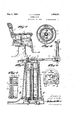
- Figure 2 is a side elevational view of my improved chair.
- Figure 3 is an enlarged vertical sectional view, through the pedestal of the chair, showing the piston or stem that carries the seat frame arranged in its lowermost position.
- Figure 5 is. a fragmentary vertical sectional view of the stem and socket, showing the pipe in the stem through which the hydraulic operating medium is conductedinto and out of the space between the lower end of the stem and the bottom of the socket in which the stem reciprocates.
- Figure 6 is a horizontal sectional view, taken on thg line 66 of Figure 3.
- Figure 7 is a top plan view of the stem and certain of the parts carried by same, partly broken away.
- t v p s Figure 8 is a vertical sectional view, taken 100.
- Fi re 10 is a horizontal sectional view, taken on the line 10-'10 of Figure 8.
- Figure 11 is a viewof the valve mechanism, comprisin a horizontal section and a vertical section, illustrating the valve mechanism set or adjusted so as to raise the seat.
- Figure 12 is, a similar view, showing the valve mechanism set or adjusted so as to lower the seat?
- Figure 13 is a view of the valve mechanism, comprising a horizontal section and a vertical section, illustrating the valve mechanism set or adjusted so as to move the back upwardly from its reclining position;
- Figure 14 is a view similar to Figure 13, showing the valve mechanism set or adjusted so as to swing the back downwardly from its normal upright position.
- chair and system I have herein illustrated my invention embodied in a barbers chair or similar chair of the kind that is equipped with a verticall adjustable seat A, a back B that can e swung upwardly and downwardly relatively to the seat so as to arrange the back either in an upright position, shown in Figure 2, or in an inclined position, commonly referred to as the reclining position of the back, a swinging apron C arranged at the front edge of the seat, and arms D combined with the apron and the back in such a' way that the apron will swing in a direction opposite to the direction of movement of the back duringfhe operation of adjusting or moving the ack relatively to the seat.
- the seat, back and apron are carried by a seat frame E, which is connected to the upper end of a vertically-movable piston or stem F that reciprocates in a vertically-disposed cylinder or socket G that is sustained and surrounded by a pedestal H which rests upon the floor of the room in which the chair is located, the stem F being provided at its upper end with a horizontally-disposed flange 1, as shown in Figure 7, to which the seat frame is attached.
- the upward movement of the seat frame E and the parts carried by same is effected by admitting a non-compressible liquid under pressure, such as oil, into the space between the lower end of the stem F and the bottom of the socket G,
- the non-compressible liquid under pressure to act directly upon a piston I that is reciprocatingly mounted in a horizontallyconsisting and adapted to exert suflicient frictional pressure on the side wall of the socket G to revent the stem from turning or rotating 1n the socket.
- Said locking device K is normally maintained in an active or o rative condition by the force or pressure w ich the hydraulic operating medium exerts on a vertically-movable piston L that reciprocates in a cylinder M, as shown in Figure 8, said piston L being provided with a depending piston rod 4 whose lower end acts upon a lever 5 that is adapted to be moved by the piston L in a direction to render the locking device K operative and which is adapted to be moved in the o posite direction, so as to release the stem loc ing device K, by a spring 6 that exerts pressure on said lever 5 in a direction tending to move the outer end or free end of said lever upwardly.
- my improved chair is that it is particularly adapted for use in a chair system for barber shops, beauty parlors and the like, that comprises a plurality of chairs, and a supply line N common to all of the chairs of the system filled with an hydraulic medium under pressure that is adapted to be admitted by valve mechanisms under control of the operators in charge of the chairs, to the cylinders associated with the seat frames, with the backs and with the causing the hydraulic medium to act directly on the pistons that are used to effect the movement or change the position of the adjustable elements of the chairs.
- any suitable means can be used for maintaining the hydraulic operating medium under pressure and for causing said operating medium to circulate from the respective chairs of the system back to the source of supply from which said operating medium is drawn to operate the chairs.
- a pressure pump will be used to maintain a non-compressible liquid, such as oil, in the supply line N under pressure
- any suitable means such as a gravity return system or a suction device, can be used to cause the operating medium to circulate from the chairs back to the device which puts said operating medium under pressure and causes it to remain in readiness to actuate the pistons of any chair when the operator in charge of the chair manipulates the valve mechanism of said chair that controls the operating Figure 1 the pressure su pl from a tank 0 partially fiiled line N leads with oil, and
- the system comprises a return line N, common to all of the chairs of the system, that leads to a tank 0', shown in Figure 1, whose lower end is connected by means of a pipe 10 with the inlet of the pressure pump 8, thereby causing oil to be withdrawn from the tank 0' and pumped into the tank 0 when the pump 8 is in operation.
- the pipe 10 is provided with a check valve 10 arranged so that V the oil can fiow only in one direction through said pipe, i.
- Any suitable means can be used to maintain a certain approximate pressure in the supply tank 0, one means that is suitable for this purpose consisting of a by-pass 11 connected to the lower end portions of the tanks 0 and O and provided with a pressure relief valve 12 set or adjusted so that when a certain approximate pressure is created in the tank 0, said valve will open and thus permit the oil to circulate from the tank 0 through the bypass 11 into the tank 0'.
- the system may comprise a suction pump 13 oper* ated by the motor 9, and having its intake 14 connected with the upper end portion of the tank 0', so as to produce or create a partial vacuum in the tank 0 that insures the hydraulic operating medium returning from the chairs back to the tank 0 from which the pressure pump 8 draws its source of supply of liquid.
- the system be so constructed and arranged that the cylinders of the chairs of the system may be placed in direct communication with the pressure supply line N when the valve mechanisms of the chairs are manipulated to adjust or operate the chairs, thereby causing the pressure that exists in the supply line N to be exerted directly on the pistons associated with the cylinders of the chairs, through the, agency of columns of nonecompressible liquid.
- Each chair of the system is equipped with a valve mechanism that is preferably'mounted at the upper endvof the stem F inside of same, so that it will not add materially to the overall length of the stem, and thus re-. strict the range of vertical movement of the ing P and provi ed with an internal passageway or port 15 and two external passageways or ports 16 and 17, as shown more clearl in Figure 11. IV-hen said valve is turned into the position shown in Figure 11 the internal passageway 15 oflsame will establish communication between a vertically-disposed in-,
- the stem F being preferably made hollow so that it will serve as a sump. or discharge reservoir for the hydraulic operating medium after said operating medium has performed its function.
- the external passageway 17 of the valve R establishes communication between the cylinder M in the valve casing and a discharge port 21 that terminates in the periphery or exterior of the valve casing.
- the inletduct 18 in the valve casing is in direct communication at all times with an extensible conduit T, shown in Figure 3 and hereinafter more fully described, that leads from the pressure supply line N and extends upwardly through the stem, said extensible conduit T and the inlet duct 18 in the valve casing being normally filled with liquid that is maintained under the same pressure 'as the liquid in the supply line N.
- an extensible conduit T shown in Figure 3 and hereinafter more fully described
- the valve R is so constructed that the external passagewa 17 in same moves into registration with t e discharge port 21 in the valve casing and with a passageway 22 in the upper end ortion of the side wall of the cylinder M be ore the internal passageway 15 of the valve R moves into registration with the inlet duct 18 and the passageway 19 in the valve casing, thereby ermitting the operating medium to escape rom the cylinder M and release the stem locking device K before the stem starts to move upwardly.
- the external passageway 16 in the periphery of said valve establishes communication between the discharge port 21 in the valve casing and the'passageway 22, previously described, in the upper end portion of the side wall of the cylinder M, thereby relieving the pressure on the piston L and permitting the stem locking device K to assume an inactive or inoperative position.
- the external port 16 is of similar construction to the external port 17, previously described, in that it is so proportioned and designed that when the valve R is moved to its lowering position, the pressure on the piston L associated with the stem locking device will be relieved, thereby rendering the stem locking device inoperative before the internal passageway 15 of the valve R reaches such a .position as to permit the liquid that sustains the stemto escape from the space between the lower end of the stem and the bottom of the socket or cylinder in which said stem opthe operating medium which has been admitted to the space between thelower end of the stem and the bottom of the socket G, will become trapped in said space, thereby causing the stem to come to rest and remain at the level at which it stood when the internal passageway 15 of the valve R moved out of registration with the passageway 19 in the valve casing.
- valve R if the valve R is moved from its lowering position shown in Figure 12, into its neutral position, the escape of the operating medium from the space between the end of the stem and the bottom of the socket through the pipe 20 will be cut oil, with the result that the stem will come to rest at the level at which it stood when the internal passageway 15 of the valve moved out of registration with the passageway 19 in the valve casing.
- Movement of the valve B into its neutral position causes the stem locking device K to become operative automatically, due to-the fact that the external passageway 17 of the valve R moves into registration with the inlet duct 18 in the valve casing and the passageway 22 in the upper end of the cylinder M, and thus permits the operating medium to enter said cylinder, as indicated by the arrows in Figure 8 and exert pressure on the piston L in a direction to force it downwardly in opposition to thespring 6.
- valve mechanism in such a way that the valve R which controls the raising and lowering of the seat of the chair, also controls the stem locking device K and causes said stem locking device to be released automatically when said valve is manipulated to efieet a change in the position of the seat, and to be rendered operative automatically when said valve is restored to its neutral position, it is not absolutely essential that the valve mechanism be constructed in this way.
- the stem locking device be governed by an hydraulic mediumwhich is controlled by a valve means, preferably a valve means designed so that the stem locking device will be released just before the stem starts to move to change the position of the seat, and will be rendered operative just after the stem comes to rest after it has been actuated to effect a change in the position of the seat.
- a valve means preferably a valve means designed so that the stem locking device will be released just before the stem starts to move to change the position of the seat, and will be rendered operative just after the stem comes to rest after it has been actuated to effect a change in the position of the seat.
- a valvemechanism comprises a single valve
- valve R that governs the raising and lowering of the seat and also governsthe device that normally holds the seat against rotar movement, and it insures the seat of the c air being held securely against rotary movement at all times, except when the seat is being raised or lowered or revolved, by a locking device that is governed by the nydraulic medium that is used to raise and 7 lower the seat.
- the valve S is also preferably of the plug type and is oscillatingly mounted in the valve casing P, asshown in Figures 11 to 14, inclusive. Said valve S is provided with two external passageways 24 and 25 arranged at opposite sides of the valve.
- the passageway 24 will establish communication between the inlet duct 18 in the valve casing and a passageway 26 in the valve casing that is connected with a pipe 27 which leads to the outer end of the cylinder J, thereby causing the operating medium to pass from the source of supply, to wit, the extensible conduit T, into the outer end of the cylinder J, as indicated by the arrows shown in Figure 14 and exert pressure on the piston I in a direction to move said piston inward 1y, with the result that the apron G of the chair will swing upwardly and the back will swing downwardly towards or into its reclining position.
- the other external passageway 25 in the valve establishes communication between a discharge port 28 in the valve casing. that terminates in the underside of said casing and a passageway 28 in the valve casing that communicates with a pipe 29 which is at tached to the inner end of the cylinder J, thereby causing the operating medium in said cylinder that is located in front of the piston I to be positively expelled throughthe pipe 29, as indicated by the arrows in Figure 14, and discharged'through the port 28 into the sump formed by the hollow stem of the chair.
- the valve casing P is preferably construct ed from a casting positioned inside of the upper end portion of the stem F, as shown in Figure 3, and supported by an inwardlyprojecting flange or rib 30 on the stem, as shown in Figure 3.
- the extensible conduit T previously referred to, that is used to conduct the-operating medium from the supply pipe N to the inlet duct 18 in the valve casing P mayKbe any suitable type or kind of conduit that will provide for the vertical movement of thestem upwardly and downwardly. In the form of my invention herein illustrated said extensible conduit.
- T is composed of a movable section 'or tube 31 that projects downwardly from the valve casing, and a stationary section or tube 32 arranged in telescopic relation with said movable tube 31'and having its lower end in communication with a branch 33 leading from the pressure supply line N, the joint or space between said tubes 31 and 32 being closed by a packing 34 of any suitable kind that makes said joint tight.
- stationary overflow pipe 35 is attached to the bottom of the socket G and extends upwardly through a hole in the lower end of the stem F, said stem being provided with a packing 36 of any preferred kind, so as to maintain a tight joint between the stem and the stationary, vertically-disposed overflow pipe 35 on which it slides.
- a chamber 37 which communicates with the interior of said ipe, said chamber 37 being connected by a ranch 38 with the return pipe N of the circulating systemt
- This chamber 37 can be of any preferred construction, but it is herein illustrated as being formed by two horizontallydisposed plates 39 and 39 arran ed in superimposed relation at the lower end of the socket G and combined with the same in such a way that the late 39" forms the top wall of the chamber 3 and also serves as the bottom of the socket G, the pipe 35 being connected to said top plate 39 and thestationary tube 32 of the extensible conduit T being rigidly connected to the bottom late 39.
- the branch 38 on the return pipe is connected to a cored passageway in the bottom plate 39, as shown in Figure 6, and a discharge hole 40 is formed in said plate so as to establish communication between the chamber 37 and the cored passageway in the plate to which the branch 38 is connected.
- a chair ofthe construction above described is quiet in operation, due to the fact that the medium used to operate the chair is not permitted to exhaust to the atmosphere, and it is easy to keep clean and in a sanitary condition, due to the fact that the operating medium is confined in a closed circulating system from which it cannot escape and collect on exposed parts of the chair.
- the means that is used to actuate the valves of the valve mechanism consists of a horizontally-disposed operating shaft U arranged transversely of the seat frame E of the. chair, beneath the seat, a longitudinally-shiftable rod W in the shaft U, a handle X on the shaft U by which said shaft can be rocked in opposite directions, and a device Y in the handle X that is capable of being oscillatedin opposite directions, so as to reciprocate the rod W.
- the shaft U is journaled in bearings 41 on the valve casing P and is provided with a toothed member, preferably a beveled gear 42, that meshes with a beveled gear 43 attached to the upper end of the valve B.
- an elongated slot or opening 44 is formed in the shaft U, as shown in Figure 7, and the rod W is provided with an arm 45 that projects through said slot, said arm 45 being connected to the valve S in any suitable way, as, for example, by an upwardly-projectin arm 46 on the valve S that projects into a ifurcated portion of the arm 45, as shown in Figures 7 and 8;
- the device Y previously referred to, that is oscillatingly mounted in the handle X, is provided at its upper end with a knob or finger piece 47 that can be grasped to turn the device Y, and the lower end portion of said device is provided with a bifurcated arm 48, shown in Figure 7, that straddles or embraces a pin 49 on the rod W.
- valve operating means of the construction above described the operator in charge of the chair can effect the adjustment of all of the parts of the chair with one hand. For example, if it is desired to raise the seat, the operator merely rocks the arm X in one direction, thereby causing the valve R to be moved into such a position as to cause the operating medium to exert upward pressure on the stem F and cause said stem and the parts carried by same to move upwardly, it being of course understood that the movement of the valve R towards its raised position shown in Figure 11 causes the stem locking device K to be released before the operating medium exerts pressure on the stem in a direction to move it upwardly.
- the operator turns the button 47 in the opposite direction, thereby causing the o crating medium to exert pressure on the piston I in a direction to force said piston outwardly or towards the outer end of the cylinder J in which it moves.
- a chair system of the character above described is superior in many respects to the con-.
- ventional chair systems used in barber shops, beauty parlors and similar establishments, due to the fact that it comprises one source of power for operating all of the chairs of the system, to wit, an hydraulic medium under pressure, that is governed by valve mechanisms on the chairs, which are of such construction that no means or agency other than the hydraulic operating medium is required to actuate or move the adjustable elements of the chairs, such as the seats, backs and stem locking devices.
- Said hydraulic operating medium is confined in a closed circulating system and is always in readiness to act upon the pistons of each chair of the system, and another advantage of such a systemis that it is quiet in operation, and also clean and sanitary.
- a vertically-adjustable, hollow stem that serves as a sump'or discharge reservoir for thevhydraulic medium used to operate the chair, and an overflow pipe arran ed so that when the stem moves upwardly the operating medium in said sump will escape automatically from same through said overflow pipe.
- a vertically-disposed socket a hollow stem reciprocatingly mounted in said socket, that carries the seat frame of the chair, a valve mechanism at the upper end of the stem adapted to be actuated to 5 permit an hydraulic operating medium under pressure to be admitted to the space between the bottom of the socket and the-end of the stem for raising the stem and to .
- a vertically-disposed socket In a barbers chair or the like of the hydraulic type, a vertically-disposed socket, a hollow stem reciprocatingly mounted in said socket, that carries the seat frame of v the chair, a valve mechanism at theupper end of the stem arranged inside of same and adapted to be manipulated to cause an operating medium under pressure to be admitted to or exhausted from said socket to raise or lower the stem, said valve mechanism comprising a port or outlet through which the operating medium is discharged into the stem after said operating medium has performed its function, a pressure supply line that always remains in direct com munication with the inlet duct in said valve mechanism, and means for preventing the exhaust operating medium from rising above a certain level in the stem.
- a chair provided with a vertioally-adjustable seat, a back that can be moved relatively to said seat, a locking device for holding the seat against rotary movement, a cylinder and piston associated with each of said. elements for effecting the movement of same, a valve mechanism for controlling the admission and discharge of an hydraulic operatmg medium under pressure to and from said cylinders, and an operating means for said valve mechanism comprising one member that is adapted to be moved in opposite directions to raise and lower the seat and con-- trol said locking device, and a different memher that is adapted to be moved in opposite directions to shift the back into and out of its reclining position.
- a chair provided with a vertically-ad
- justable seat a back that can be moved relatively to the seat
- a locking device for holding the seat against rotary movement
- cylinders provided with istons for effecting the movement of said e ements
- a valve mechaw nism for controlling the admission and discharge of an hydraulic operating medium under pressure to and from said cylinders, comprising one valve that is adapted to be manipulated to release the locking device and thereafter cause the seat to move, and another valve that is adapted to be manipulated to cause the back to move.
- a barbers chair or the like provided with a vertically-adjustable seat, a back that can be moved relatively to the seat, a locking device for holding the seat against rotary movement, separate cylinders associated with said seat, back and lockin device and provided with pistons for moving said elements, a I valve mechanism for admitting an hydraulic medium under pressure to and from said cylinders, an operating means for said valve mechanism comprising a controlling member that is adapted to be swung inone direction from a neutral position to release the locking device and raise the seat, or swung in the opposite direction from its neutral position to release the locking device and lower the seat, and a part carried by said controlling member that is adapted to be shifted in opposite directions to move the back into and out of its reclining position.
- a barbers chair or the like of the hydraulic type a seat that is adapted to be raised, lowered and rotated, a controlling means for the hydraulic operating medium that moves with the seat, and conduits through which the hydraulic medium is supplied to and conducted away from said controlling means, composed of elements arrgnged in telescopic and rotating relations 1p.
- a stem that carries the seat frame of the chair reciprocatingly mounted in a vertically-disposed socket, a valve mechanism arranged at the upper end of said stem and provided with valves for controlling an hydraulic operating medium under pressure that is used to raise and lower the seat and move the back relatively to the seat, and an operating means for said valve mechanism comprising a rock shaft that actuates one of the valves, and a reciprocating rod in said shaft that actuates adii Schlt valve of the valve mechanism.
Landscapes
- Chairs For Special Purposes, Such As Reclining Chairs (AREA)
- Chairs Characterized By Structure (AREA)
Description
L. A. CARTER BARBER CHAIR May 3, 1932.
Filed Feb. 15, 1929 I4 Sheets-Sheet r M y 3, 1932- A. CARTER 1,856,691
BARBER CHAIR Filed Feb. 15, 1929 4 Sheets-Sheet 2 I III HHIHH' A 55 ATTP/VEKS L. A. CARTER May 3, 1932.
BARBER CHAIR -4 Sheets-Sheet 3 Filed Feb. 15, 1929 A. CARTER May 3, 1932.
BARBER CHAIR 4 Sheets-Sheet '4 Filed Feb. 15, 1929 Z7 l/w /YTOE L/one/ (4. Ear/en HTTWF /YEI j Patented May 3, 1932 UNITED STATES PATENT OFFICE LIONEL A. CARTER, OI WEBSTER GROVES, MISSOURI, ASSIGNOR 'IO KOKEN COM- PANIES, OF ST. LOUIS, MISSOURI, A CORPORATION OF DELAWARE BARBER CHAIR Application filed February 15, 1929. Serial No. 840,157.
This invention relates to adjustable chairs of the kind that are used in barber shops, beauty parlors and similar establishments, and particularly, chairs of the type in ,whlch an hydraulic medium is used to raise or lower the seat of the chair.
One object of my invention is to provide a chair system for barber shops, beauty parlors and similar establishments, that com- -l0 prises a plurality of chairs of the type in which the seat can be raised and lowered and the back can be adjusted relatively to the seat, a pressure supply line common to all of the chairs of the system filled with an hydraulic operating medium under pressure, and a valve mechanism associated with each chair for enabling the operator in charge of the chair to cause the hydraulic operating medium in the supply line to exert pressure 20 directly on devices which efiect the movement of the adjustable elements of the chair.
Another object is to provide a chair system of the general kind mentioned, which is of such construction that the chairs can be .1 operated or adjusted without liability of producing an objectionable noise in the room in which they are located, and withoutli ability of the hydraulic operating medium escaping from the portions of the chair in which said operating medium is confined or through which it circulates.
Another object is to provide a barbers chair or the like in which an hydraulic medium under pressure is .used to raise and lower the seat, to swing the back into and out of its reclined position, and to govern a locking device that normally holds the seat of the chair against rotary movement.
Another object is to provide a barbers 40 chair or the like of the hydraulic type, that is equipped with a reliable valve mechanism of simple design for governing the circulation of the hydraulic operating medium, arranged inside of the stem of the chair in such a position that it does not interfere with or restrict the downward movement oiithe stem into the socket of the chair, thereby making it ossible to. proportion or design the stem an socket so that the seat is capable of a relatively great range of vertical movement, even though the socket is made short enough to permit the seat to assume a relatively low position.
Another object is to provide a barbers chair or the like of the hydraulic type, that is equipped with a valve mechanism, and an operating means for said valve mechanism which is of novel desi n and such construction that the operator 1n charge of the chair merely has to move a governing member in opposite directions to raise and lower the seat, and merely has to turn a button or finger piece on said governing member in o posite directions to cause the hydraulic me ium to move the back of the chair into and out of its reclining position, or hold said back inan intermediate position, the said movements of the governing member also being used to control a locking device that holds the seat of the chair against rotary movement.
And still another object of my invention is to provide a barbers chair or the like that is equipped with a stem locking device, and an hydraulic means for controllin said device. Other objects and desirable eatures of 75 my invention will be hereinafter pointed out.
Figure 1 of the drawings illustrates a chair system constructed in accordance with my invention.
Figure 2 is a side elevational view of my improved chair.
Figure 3 is an enlarged vertical sectional view, through the pedestal of the chair, showing the piston or stem that carries the seat frame arranged in its lowermost position.
-Figure 4: is a horizontal sectional view,
taken on the line 4-4 of Figure 3.
Figure 5 is. a fragmentary vertical sectional view of the stem and socket, showing the pipe in the stem through which the hydraulic operating medium is conductedinto and out of the space between the lower end of the stem and the bottom of the socket in which the stem reciprocates.
Figure 6 is a horizontal sectional view, taken on thg line 66 of Figure 3.
Figure 7 is a top plan view of the stem and certain of the parts carried by same, partly broken away. t v p s Figure 8 is a vertical sectional view, taken 100.
on the line 8-8 of Figure 7, looking in. the direction indicated by the arrows. I
-Fi re 9 is a horizontal sectional view,
taken on the line 9'-9 of Figure 8.
Figure 11 is a viewof the valve mechanism, comprisin a horizontal section and a vertical section, illustrating the valve mechanism set or adjusted so as to raise the seat.
Figure 12 is, a similar view, showing the valve mechanism set or adjusted so as to lower the seat? Figure 13 is a view of the valve mechanism, comprising a horizontal section and a vertical section, illustrating the valve mechanism set or adjusted so as to move the back upwardly from its reclining position; and
Figure 14 is a view similar to Figure 13, showing the valve mechanism set or adjusted so as to swing the back downwardly from its normal upright position.
General description of chair and system I have herein illustrated my invention embodied in a barbers chair or similar chair of the kind that is equipped with a verticall adjustable seat A, a back B that can e swung upwardly and downwardly relatively to the seat so as to arrange the back either in an upright position, shown in Figure 2, or in an inclined position, commonly referred to as the reclining position of the back, a swinging apron C arranged at the front edge of the seat, and arms D combined with the apron and the back in such a' way that the apron will swing in a direction opposite to the direction of movement of the back duringfhe operation of adjusting or moving the ack relatively to the seat. The seat, back and apron are carried by a seat frame E, which is connected to the upper end of a vertically-movable piston or stem F that reciprocates in a vertically-disposed cylinder or socket G that is sustained and surrounded by a pedestal H which rests upon the floor of the room in which the chair is located, the stem F being provided at its upper end with a horizontally-disposed flange 1, as shown in Figure 7, to which the seat frame is attached. The upward movement of the seat frame E and the parts carried by same is effected by admitting a non-compressible liquid under pressure, such as oil, into the space between the lower end of the stem F and the bottom of the socket G,
and thedownward movement of said seat frame is efiected by permitting said liquid to escape from said space. The movement of the back relatively to the seat, into and out of 'its reclined position, is effected by causing the hydraulic operating medium,
to wit, the non-compressible liquid under pressure, to act directly upon a piston I that is reciprocatingly mounted in a horizontallyconsisting and adapted to exert suflicient frictional pressure on the side wall of the socket G to revent the stem from turning or rotating 1n the socket. Said locking device K is normally maintained in an active or o rative condition by the force or pressure w ich the hydraulic operating medium exerts on a vertically-movable piston L that reciprocates in a cylinder M, as shown in Figure 8, said piston L being provided with a depending piston rod 4 whose lower end acts upon a lever 5 that is adapted to be moved by the piston L in a direction to render the locking device K operative and which is adapted to be moved in the o posite direction, so as to release the stem loc ing device K, by a spring 6 that exerts pressure on said lever 5 in a direction tending to move the outer end or free end of said lever upwardly.
One advantage of my improved chair is that it is particularly adapted for use in a chair system for barber shops, beauty parlors and the like, that comprises a plurality of chairs, and a supply line N common to all of the chairs of the system filled with an hydraulic medium under pressure that is adapted to be admitted by valve mechanisms under control of the operators in charge of the chairs, to the cylinders associated with the seat frames, with the backs and with the causing the hydraulic medium to act directly on the pistons that are used to effect the movement or change the position of the adjustable elements of the chairs. In such a chair system any suitable means can be used for maintaining the hydraulic operating medium under pressure and for causing said operating medium to circulate from the respective chairs of the system back to the source of supply from which said operating medium is drawn to operate the chairs. Usually, a pressure pump will be used to maintain a non-compressible liquid, such as oil, in the supply line N under pressure, and any suitable means, such as a gravity return system or a suction device, can be used to cause the operating medium to circulate from the chairs back to the device which puts said operating medium under pressure and causes it to remain in readiness to actuate the pistons of any chair when the operator in charge of the chair manipulates the valve mechanism of said chair that controls the operating Figure 1 the pressure su pl from a tank 0 partially fiiled line N leads with oil, and
rovided at its up r end with an inlet pipe vertical adjustments of the seat frame and ?that leads fromt e dischargeside of a presalso, to control the stem locking device K.
Seat controlling mechanism Each chair of the system is equipped with a valve mechanism that is preferably'mounted at the upper endvof the stem F inside of same, so that it will not add materially to the overall length of the stem, and thus re-. strict the range of vertical movement of the ing P and provi ed with an internal passageway or port 15 and two external passageways or ports 16 and 17, as shown more clearl in Figure 11. IV-hen said valve is turned into the position shown in Figure 11 the internal passageway 15 oflsame will establish communication between a vertically-disposed in-,
let duct 18 in the valve casing, located at approximately the center of said casing, and a passageway 19 in the valve casing Whose outer end communicates with a pipe 20 arranged vertically inside of the stem F, with its lower end terminating in the bottom end Wall of the stem, as shown in Figure 5, the stem F being preferably made hollow so that it will serve as a sump. or discharge reservoir for the hydraulic operating medium after said operating medium has performed its function. At such times the external passageway 17 of the valve R establishes communication between the cylinder M in the valve casing and a discharge port 21 that terminates in the periphery or exterior of the valve casing. The inletduct 18 in the valve casing is in direct communication at all times with an extensible conduit T, shown in Figure 3 and hereinafter more fully described, that leads from the pressure supply line N and extends upwardly through the stem, said extensible conduit T and the inlet duct 18 in the valve casing being normally filled with liquid that is maintained under the same pressure 'as the liquid in the supply line N. In this position of the valve R, i. e., the position shown in Figure 11, the hydraulic operating medium will pass through the internal passageway 15 in the valve R, thence downwardly through the pipe 20 into the space between'the lower end of the stem F and the bottom of the socket G, as indicated by the arrows, and exert pressure, on the stem in a direction to raise said stem and the parts of the chair carried by same. During the upward movement of the in ,position, shown in Figure 11. Preferab y, the valve R is so constructed that the external passagewa 17 in same moves into registration with t e discharge port 21 in the valve casing and with a passageway 22 in the upper end ortion of the side wall of the cylinder M be ore the internal passageway 15 of the valve R moves into registration with the inlet duct 18 and the passageway 19 in the valve casing, thereby ermitting the operating medium to escape rom the cylinder M and release the stem locking device K before the stem starts to move upwardly. 'The liquid operating medium that escapes from the cylinder M discharges through the port 21 in the valve casing, downwardly into the hollow interior of the stem F that constitutes'the sump or discharge reservoir for the operating medium, the said liquid being positively expelled from the cylinder M by the upward movement produced on the piston L by the expansion of the spring 6 which constantly exerts upward pressure on the outer end or free end of the actuating lever 5 of the stem locking device.
When the valve R is moved into its other position, shown in Figure 12, which position I will refer to as its lowering position, the internal passageway 15 of said valve will establish communication between the passageway 19 in the value casing and a separate discharge port 23 whose outer end terminates in the exterior of the valve casing, thereby causing the liquid in the space between the lower end of the stem F and the bottom of the socket G to flow up"- wardly through the pipe 20, thence through the internal passageway 15 of the valve R and finally discharge through the port 23 in the valve casing downwardly into the sum or internal space of the stem, as indicate by the arrows in Figure 12, the operating medium being positively forced out of or expelled from the space between the lower end of the stem and the bottom of the socket by the pressure which the weight of the stem and the load thereon exerts on said operating medium. In this position of the valve R, i. e., its lowering position, the external passageway 16 in the periphery of said valve establishes communication between the discharge port 21 in the valve casing and the'passageway 22, previously described, in the upper end portion of the side wall of the cylinder M, thereby relieving the pressure on the piston L and permitting the stem locking device K to assume an inactive or inoperative position. The external port 16 is of similar construction to the external port 17, previously described, in that it is so proportioned and designed that when the valve R is moved to its lowering position, the pressure on the piston L associated with the stem locking device will be relieved, thereby rendering the stem locking device inoperative before the internal passageway 15 of the valve R reaches such a .position as to permit the liquid that sustains the stemto escape from the space between the lower end of the stem and the bottom of the socket or cylinder in which said stem opthe operating medium which has been admitted to the space between thelower end of the stem and the bottom of the socket G, will become trapped in said space, thereby causing the stem to come to rest and remain at the level at which it stood when the internal passageway 15 of the valve R moved out of registration with the passageway 19 in the valve casing. Likewise, if the valve R is moved from its lowering position shown in Figure 12, into its neutral position, the escape of the operating medium from the space between the end of the stem and the bottom of the socket through the pipe 20 will be cut oil, with the result that the stem will come to rest at the level at which it stood when the internal passageway 15 of the valve moved out of registration with the passageway 19 in the valve casing. Movement of the valve B into its neutral position causes the stem locking device K to become operative automatically, due to-the fact that the external passageway 17 of the valve R moves into registration with the inlet duct 18 in the valve casing and the passageway 22 in the upper end of the cylinder M, and thus permits the operating medium to enter said cylinder, as indicated by the arrows in Figure 8 and exert pressure on the piston L in a direction to force it downwardly in opposition to thespring 6.
While I prefer to construct the valve mechanism in such a way that the valve R which controls the raising and lowering of the seat of the chair, also controls the stem locking device K and causes said stem locking device to be released automatically when said valve is manipulated to efieet a change in the position of the seat, and to be rendered operative automatically when said valve is restored to its neutral position, it is not absolutely essential that the valve mechanism be constructed in this way. The essential thing, so far as the stem locking device is concerned, is that it be governed by an hydraulic mediumwhich is controlled by a valve means, preferably a valve means designed so that the stem locking device will be released just before the stem starts to move to change the position of the seat, and will be rendered operative just after the stem comes to rest after it has been actuated to effect a change in the position of the seat. I prefer, however, to construct the valve mechanism in the manner above described, because such a valvemechanism comprises a single valve,
to wit, the valve R, that governs the raising and lowering of the seat and also governsthe device that normally holds the seat against rotar movement, and it insures the seat of the c air being held securely against rotary movement at all times, except when the seat is being raised or lowered or revolved, by a locking device that is governed by the nydraulic medium that is used to raise and 7 lower the seat.
Back controlling mechanism opposite directions from its neutral position will cause the back to be raised or lowered: The valve S is also preferably of the plug type and is oscillatingly mounted in the valve casing P, asshown in Figures 11 to 14, inclusive. Said valve S is provided with two external passageways 24 and 25 arranged at opposite sides of the valve. When said valve is moved into the position shown in Figure 14, the passageway 24 will establish communication between the inlet duct 18 in the valve casing and a passageway 26 in the valve casing that is connected with a pipe 27 which leads to the outer end of the cylinder J, thereby causing the operating medium to pass from the source of supply, to wit, the extensible conduit T, into the outer end of the cylinder J, as indicated by the arrows shown in Figure 14 and exert pressure on the piston I in a direction to move said piston inward 1y, with the result that the apron G of the chair will swing upwardly and the back will swing downwardly towards or into its reclining position. In this postion of the valve S the other external passageway 25 in the valve establishes communication between a discharge port 28 in the valve casing. that terminates in the underside of said casing and a passageway 28 in the valve casing that communicates with a pipe 29 which is at tached to the inner end of the cylinder J, thereby causing the operating medium in said cylinder that is located in front of the piston I to be positively expelled throughthe pipe 29, as indicated by the arrows in Figure 14, and discharged'through the port 28 into the sump formed by the hollow stem of the chair.
When the valve S is movedinto its other position, shown in Figure 13, the external passageway 25 in said valve establishes communication between the inlet duct 18 in the' valve casin and the pipe 29 attached to the inner end 0 vthe cylinder J, and the passageway 24 in said valve establishes communication between the discharge port 28 in' the valve-casing and the pipe 27 that is attached to the outer end of the cylinder J, thereby causing-the operating medium tobe admitted to the inner end of the cylinder J, with the result that the piston I will move outwardly and cause the back of the chair to be restored to or moved towards its upright position, the operating medium in the outer end portion of the cylinder J escaping fromsame through the pipe 27, and discharging into the sump.
When the valve S is moved from either of its positions above described into its neutral position, shown in Fi ures 11 and 12, communication is cut off etween the inletduct 18 in the valve casingand both ends of the cylinder J, and communication is also cut off between both ends of said cylinder and the discharge port 28 in the valve casing. Accordingly, the back of the chair will be held securely locked in the position-into which it has been moved by the same means or medium which is used to effect the adjustment of the back.
Ewtensz'ble conduit and overflow pipe The valve casing P is preferably construct ed from a casting positioned inside of the upper end portion of the stem F, as shown in Figure 3, and supported by an inwardlyprojecting flange or rib 30 on the stem, as shown in Figure 3. The extensible conduit T, previously referred to, that is used to conduct the-operating medium from the supply pipe N to the inlet duct 18 in the valve casing P mayKbe any suitable type or kind of conduit that will provide for the vertical movement of thestem upwardly and downwardly. In the form of my invention herein illustrated said extensible conduit. T is composed of a movable section 'or tube 31 that projects downwardly from the valve casing, and a stationary section or tube 32 arranged in telescopic relation with said movable tube 31'and having its lower end in communication with a branch 33 leading from the pressure supply line N, the joint or space between said tubes 31 and 32 being closed by a packing 34 of any suitable kind that makes said joint tight. In order that the operating medium which is discharged into the hollow stem F from the valve mechanism ,will be returned automatically to the source of supply, or
rather, to the return pipe N of the system, a
From the foregoing it will be seen that in my improved chair an hydraulic operating medium under pressure is always maintained in readiness to exert pressure on the pistons associated with the seat, back and stem locking device whenever the valve mechanism is manipulated to operate the chair, the act of opening a valve of said mechanism causing the pressure that exists in the supply line N to be exerted directly on the piston or other part controlled by said valve through the agency of substantially a solid column of noncompressible liquid. After performing its function said operating medium escapes from the cylinder to which it was admitted, back to the sump formed by the hollow stem of the chair, and thence from said sump back to the source of supply through the return line N, the sump being of such a character that the operating medium will drain out of same automatically when the operating medium in the sump reaches a certain level. In
addition to the desirable features or charac-' teristics above pointed out, a chair ofthe construction above described is quiet in operation, due to the fact that the medium used to operate the chair is not permitted to exhaust to the atmosphere, and it is easy to keep clean and in a sanitary condition, due to the fact that the operating medium is confined in a closed circulating system from which it cannot escape and collect on exposed parts of the chair.
Operating means for 'vahv-e mechanism The means that is used to actuate the valves of the valve mechanism consists of a horizontally-disposed operating shaft U arranged transversely of the seat frame E of the. chair, beneath the seat, a longitudinally-shiftable rod W in the shaft U, a handle X on the shaft U by which said shaft can be rocked in opposite directions, and a device Y in the handle X that is capable of being oscillatedin opposite directions, so as to reciprocate the rod W. The shaft U is journaled in bearings 41 on the valve casing P and is provided with a toothed member, preferably a beveled gear 42, that meshes with a beveled gear 43 attached to the upper end of the valve B. At a. point in proximity to the valve S an elongated slot or opening 44 is formed in the shaft U, as shown in Figure 7, and the rod W is provided with an arm 45 that projects through said slot, said arm 45 being connected to the valve S in any suitable way, as, for example, by an upwardly-projectin arm 46 on the valve S that projects into a ifurcated portion of the arm 45, as shown in Figures 7 and 8; The device Y, previously referred to, that is oscillatingly mounted in the handle X, is provided at its upper end with a knob or finger piece 47 that can be grasped to turn the device Y, and the lower end portion of said device is provided with a bifurcated arm 48, shown in Figure 7, that straddles or embraces a pin 49 on the rod W. With a valve operating means of the construction above described the operator in charge of the chair can effect the adjustment of all of the parts of the chair with one hand. For example, if it is desired to raise the seat, the operator merely rocks the arm X in one direction, thereby causing the valve R to be moved into such a position as to cause the operating medium to exert upward pressure on the stem F and cause said stem and the parts carried by same to move upwardly, it being of course understood that the movement of the valve R towards its raised position shown in Figure 11 causes the stem locking device K to be released before the operating medium exerts pressure on the stem in a direction to move it upwardly. When the handle is restored to its normal upright position, indicated in Figures 13 and 14, the stem comes to rest, and thereafter, the stem locking device K becomes operative, thus causing the seat frame to be maintained at the level at which it stopped, and held securely against rotary movement. If the seat of the chair is in an elevated position and it is desired to lower the seat,the operator simply has to swing the handle X in the opposite direction from neutral position, so as to permit the operating medium confined in the space between the lower end of the stem and the bottom of the socket to escape from said 47 at the upperend of the device Y] in one direction, so as to cause the 0 rating medium to move the piston I inwar ly, and after the back has reached the position desired by the operator, said button 47 can berestored toits neutral position-so as to trap the operating medium in the cylinder J on both sides of the piston I, and thus securely hold the back in its adjusted position. To restore the backto its normal upright position, the operator turns the button 47 in the opposite direction, thereby causing the o crating medium to exert pressure on the piston I in a direction to force said piston outwardly or towards the outer end of the cylinder J in which it moves.
A chair system of the character above described is superior in many respects to the con-.
ventional chair systems used in barber shops, beauty parlors and similar establishments, due to the fact that it comprises one source of power for operating all of the chairs of the system, to wit, an hydraulic medium under pressure, that is governed by valve mechanisms on the chairs, which are of such construction that no means or agency other than the hydraulic operating medium is required to actuate or move the adjustable elements of the chairs, such as the seats, backs and stem locking devices. Said hydraulic operating medium is confined in a closed circulating system and is always in readiness to act upon the pistons of each chair of the system, and another advantage of such a systemis that it is quiet in operation, and also clean and sanitary. By employing an hydraullc me dium confined in a pressure supply line common to a plurality of chairs, to operate said chairs, I overcome the necessity of equipping each chair with an individual pump or similar pressure producing device. Accordingly, I am able to reduce the cost of the chair equipment of barber shops and similar establishments. By arranging the valve mechanism of the chair on the inside of the stem, I am able to build a chair whose seat has a relatively great range of vertical movement, not-' tor in charge of the chair, to govern the ad justment, of all of the parts of the chair.
aving thus described my invention,what
I claim asnew and desire to secure by Letters Patent of the United States is:
1. In a barbers chair or the like, of the hydraulictype, a vertically-adjustable, hollow stem that serves as a sump'or discharge reservoir for thevhydraulic medium used to operate the chair, and an overflow pipe arran ed so that when the stem moves upwardly the operating medium in said sump will escape automatically from same through said overflow pipe.
' 2. In a barbers chair or the like of the hydraulic type, a vertically-disposed socket, a hollow stem reciprocatingly mounted in said socket, that carries the seat frame of the chair, a valve mechanism at the upper end of the stem adapted to be actuated to 5 permit an hydraulic operating medium under pressure to be admitted to the space between the bottom of the socket and the-end of the stem for raising the stem and to .be
discharged from said space into the interior of the stem for lowering the stem, an overflow pipe projecting upwardly from the bottom of the socket through a hole in the lower end a of the stem, and an extensible conduit lead ing from said valve mechanism to a pressure line through which the operating medium is supplied to the valve mechanism.
3. In a barbers chair or the like of the hydraulic type, a vertically-disposed socket, a hollow stem reciprocatingly mounted in said socket, that carries the seat frame of v the chair, a valve mechanism at theupper end of the stem arranged inside of same and adapted to be manipulated to cause an operating medium under pressure to be admitted to or exhausted from said socket to raise or lower the stem, said valve mechanism comprising a port or outlet through which the operating medium is discharged into the stem after said operating medium has performed its function, a pressure supply line that always remains in direct com munication with the inlet duct in said valve mechanism, and means for preventing the exhaust operating medium from rising above a certain level in the stem.
4. A chair provided with a vertioally-adjustable seat, a back that can be moved relatively to said seat, a locking device for holding the seat against rotary movement, a cylinder and piston associated with each of said. elements for effecting the movement of same, a valve mechanism for controlling the admission and discharge of an hydraulic operatmg medium under pressure to and from said cylinders, and an operating means for said valve mechanism comprising one member that is adapted to be moved in opposite directions to raise and lower the seat and con-- trol said locking device, and a different memher that is adapted to be moved in opposite directions to shift the back into and out of its reclining position.
5,. A chair provided with a vertically-ad;
justable seat, a back that can be moved relatively to the seat, a locking device for holding the seat against rotary movement, cylinders provided with istons for effecting the movement of said e ements, a valve mechaw nism for controlling the admission and discharge of an hydraulic operating medium under pressure to and from said cylinders, comprising one valve that is adapted to be manipulated to release the locking device and thereafter cause the seat to move, and another valve that is adapted to be manipulated to cause the back to move.
' 6. A barbers chair or the like provided with a vertically-adjustable seat, a back that can be moved relatively to the seat, a locking device for holding the seat against rotary movement, separate cylinders associated with said seat, back and lockin device and provided with pistons for moving said elements, a I valve mechanism for admitting an hydraulic medium under pressure to and from said cylinders, an operating means for said valve mechanism comprising a controlling member that is adapted to be swung inone direction from a neutral position to release the locking device and raise the seat, or swung in the opposite direction from its neutral position to release the locking device and lower the seat, and a part carried by said controlling member that is adapted to be shifted in opposite directions to move the back into and out of its reclining position.
7. In a barbers chair or the like of the hydraulic type, a seat that is adapted to be raised, lowered and rotated, a controlling means for the hydraulic operating medium that moves with the seat, and conduits through which the hydraulic medium is supplied to and conducted away from said controlling means, composed of elements arrgnged in telescopic and rotating relations 1p.
8. In a barbers chair or the like of the hydraulic type a stem that carries the seat frame of the chair reciprocatingly mounted in a vertically-disposed socket, a valve mechanism arranged at the upper end of said stem and provided with valves for controlling an hydraulic operating medium under pressure that is used to raise and lower the seat and move the back relatively to the seat, and an operating means for said valve mechanism comprising a rock shaft that actuates one of the valves, and a reciprocating rod in said shaft that actuates adiiierent valve of the valve mechanism. Y
LIONEL A. CARTER.
Priority Applications (1)
| Application Number | Priority Date | Filing Date | Title |
|---|---|---|---|
| US340157A US1856691A (en) | 1929-02-15 | 1929-02-15 | Barber chair |
Applications Claiming Priority (1)
| Application Number | Priority Date | Filing Date | Title |
|---|---|---|---|
| US340157A US1856691A (en) | 1929-02-15 | 1929-02-15 | Barber chair |
Publications (1)
| Publication Number | Publication Date |
|---|---|
| US1856691A true US1856691A (en) | 1932-05-03 |
Family
ID=23332130
Family Applications (1)
| Application Number | Title | Priority Date | Filing Date |
|---|---|---|---|
| US340157A Expired - Lifetime US1856691A (en) | 1929-02-15 | 1929-02-15 | Barber chair |
Country Status (1)
| Country | Link |
|---|---|
| US (1) | US1856691A (en) |
Cited By (4)
| Publication number | Priority date | Publication date | Assignee | Title |
|---|---|---|---|---|
| US2507601A (en) * | 1946-10-30 | 1950-05-16 | Adel Prec Products Corp | Hydraulic locking apparatus |
| US2672917A (en) * | 1950-05-19 | 1954-03-23 | American Optical Corp | Adjustable chair |
| US3288454A (en) * | 1964-08-26 | 1966-11-29 | Flexible Air Seat Corp | Heavy-duty vehicle seat |
| US4884841A (en) * | 1988-06-20 | 1989-12-05 | Holley Robert E | Seating assistance device |
-
1929
- 1929-02-15 US US340157A patent/US1856691A/en not_active Expired - Lifetime
Cited By (4)
| Publication number | Priority date | Publication date | Assignee | Title |
|---|---|---|---|---|
| US2507601A (en) * | 1946-10-30 | 1950-05-16 | Adel Prec Products Corp | Hydraulic locking apparatus |
| US2672917A (en) * | 1950-05-19 | 1954-03-23 | American Optical Corp | Adjustable chair |
| US3288454A (en) * | 1964-08-26 | 1966-11-29 | Flexible Air Seat Corp | Heavy-duty vehicle seat |
| US4884841A (en) * | 1988-06-20 | 1989-12-05 | Holley Robert E | Seating assistance device |
Similar Documents
| Publication | Publication Date | Title |
|---|---|---|
| US2653648A (en) | Electric-hydraulic beauty chair | |
| US2067136A (en) | Wall bed | |
| US2687536A (en) | Adjustable bed | |
| US3724003A (en) | Hydraulic adjusting apparatus for hospital beds or the like | |
| US2168649A (en) | Invalid bed accessory | |
| US2196511A (en) | Tower wagon | |
| US2214323A (en) | Toilet accessory | |
| GB947849A (en) | Improvements in or relating to seating structures | |
| US3368845A (en) | Hydraulic adjustment barber chair | |
| US2092266A (en) | Operating table | |
| US1856691A (en) | Barber chair | |
| US1754975A (en) | Nonreturn valve | |
| US2540133A (en) | Adjustable hospital bed | |
| US2794988A (en) | Folding water closet | |
| US1517774A (en) | Theater seating equipment | |
| US2146403A (en) | Bumper jack | |
| US1364882A (en) | Barber's chair | |
| US4475714A (en) | Piano lift | |
| US2659307A (en) | Compound pressure pump | |
| US2059130A (en) | Operating chair | |
| US2270233A (en) | Chair | |
| US1841673A (en) | Hydraulic lift truck | |
| US2050000A (en) | Lift truck | |
| US2132363A (en) | Hydraulically operated reclining chair | |
| US1899534A (en) | Automobile lift |