US1856689A - Door and latch construction - Google Patents
Door and latch construction Download PDFInfo
- Publication number
- US1856689A US1856689A US83908A US8390826A US1856689A US 1856689 A US1856689 A US 1856689A US 83908 A US83908 A US 83908A US 8390826 A US8390826 A US 8390826A US 1856689 A US1856689 A US 1856689A
- Authority
- US
- United States
- Prior art keywords
- latch
- door
- plate
- edge
- bolt
- Prior art date
- Legal status (The legal status is an assumption and is not a legal conclusion. Google has not performed a legal analysis and makes no representation as to the accuracy of the status listed.)
- Expired - Lifetime
Links
- 238000010276 construction Methods 0.000 title description 14
- 239000002184 metal Substances 0.000 description 10
- 239000005357 flat glass Substances 0.000 description 9
- 239000011521 glass Substances 0.000 description 2
- 238000005452 bending Methods 0.000 description 1
- 230000006835 compression Effects 0.000 description 1
- 238000007906 compression Methods 0.000 description 1
- 230000000694 effects Effects 0.000 description 1
- 238000005728 strengthening Methods 0.000 description 1
- 239000000126 substance Substances 0.000 description 1
- 210000002105 tongue Anatomy 0.000 description 1
Images

Classifications
-
- E—FIXED CONSTRUCTIONS
- E05—LOCKS; KEYS; WINDOW OR DOOR FITTINGS; SAFES
- E05B—LOCKS; ACCESSORIES THEREFOR; HANDCUFFS
- E05B85/00—Details of vehicle locks not provided for in groups E05B77/00 - E05B83/00
- E05B85/20—Bolts or detents
- E05B85/22—Rectilinearly moving bolts
-
- Y—GENERAL TAGGING OF NEW TECHNOLOGICAL DEVELOPMENTS; GENERAL TAGGING OF CROSS-SECTIONAL TECHNOLOGIES SPANNING OVER SEVERAL SECTIONS OF THE IPC; TECHNICAL SUBJECTS COVERED BY FORMER USPC CROSS-REFERENCE ART COLLECTIONS [XRACs] AND DIGESTS
- Y10—TECHNICAL SUBJECTS COVERED BY FORMER USPC
- Y10S—TECHNICAL SUBJECTS COVERED BY FORMER USPC CROSS-REFERENCE ART COLLECTIONS [XRACs] AND DIGESTS
- Y10S292/00—Closure fasteners
- Y10S292/67—Vehicle door latches free of sash or pane
-
- Y—GENERAL TAGGING OF NEW TECHNOLOGICAL DEVELOPMENTS; GENERAL TAGGING OF CROSS-SECTIONAL TECHNOLOGIES SPANNING OVER SEVERAL SECTIONS OF THE IPC; TECHNICAL SUBJECTS COVERED BY FORMER USPC CROSS-REFERENCE ART COLLECTIONS [XRACs] AND DIGESTS
- Y10—TECHNICAL SUBJECTS COVERED BY FORMER USPC
- Y10T—TECHNICAL SUBJECTS COVERED BY FORMER US CLASSIFICATION
- Y10T292/00—Closure fasteners
- Y10T292/08—Bolts
- Y10T292/096—Sliding
- Y10T292/0969—Spring projected
- Y10T292/097—Operating means
Definitions
- This invention relates to door and latch constructions, and particularly to the combination of a door and latch adaptable for use in connection with automobile bodies.
- the principal objectof the present invention is to provide a simplified latch construction for use with a sheet metal door in which a window glass is slidable up and down.
- Another object is to provide a latch as dee scribed which may be operated from either side of the door and still allow the side edges of the window glass to be extended to a minimum distance from the outside edges of the door, thereby allowing the use of window frame side members of minimum width whereby obstruction to vision from the inside of the vehicle is reduced.
- Another object is to provide a door latch in which the stem of the outside operating handle is placed beyond the usual forward edge of the latch, and to form the edge of the door which is to receive the latch with an outwardly projecting pocket for receiving the latch stem, whereby when the latch is assembled to the door the inside face of the door side edge presents no obstruction in its length by reason of such stem.
- Fig. 1 is a perspective view of an automobile body of the closed type having doors to which the present invention is applicable.
- Fig. 2 is a perspective View of a suitable embodiment of a door latch constructed in accordance with the present invention and which is applicable to doors such as shown in Fig. 1 when constructed in accordance with the present invention.
- Fig. 3 is a fragmentary perspective view 50 of therear left door of the automobile body Serial No. 83,908.
- FIG. 1 illustrating the manner in which it has been formed in accordance with the present invention.
- Fig.4 is a fragmentary perspective view corresponding to the view in Fig; 3 but showing the latch of Fig. 2 in assembled relation therewith, the handles for operatingjthe latch being shown in operative relation thereto.
- Fig. 5' is a view corresponding to the view of Fig. & but showing the window glass and window glass retaining and guiding channel in assembled relation thereto.
- Fig; 6 is a sectional view of Fig. 5 taken in a horizontal plane through the center of the outside latch handle stem.
- Fig. 7 is a sectional view of Fig. 5taken in a horizontal plane through the center of the latch bolt.
- Fig. 8 is a fragmentary perspective view of the door and its'co-operating pillar post
- Fig. 9 is a perspective view of the latch bolt, roll-back cam and outside operating handle, insideoperating lever, and locking dog and handle, all in operative relationship with each other, to more clearly show the re lation they normally bear to each other.
- Fig. 10- is a perspective'view'ofthelatch plate.
- Fig. 11 is'a plate cover.
- H p Fig. 12 is aview of the latch bolt projectmg spring.
- Fig. 13 is a perspective view of the locking dog spring.
- Fig. 14 is a perspective view of the inside operating handle return and anti-rattle spring.
- Fig. 15 is a perspective view taken from the latch plate side of the latch plate cover showing the relation of the locking dog and the locking'dog spring to each other'and to the latch plate cover.
- the door latch as shown in the several views, is built up on the latch plate 25 shown alone in perspective in Fig. 10.
- the plate perspective view of the latch 25 is provided with an outer or forward edge flange provided with a bolt receiving opening 27, and an inner or rear edge flange 28 provided with an opening 29 for receiving the guiding tail of the latch bolt. It is also provided with an extending portion 30, which projects out past the outer flange 26 which define the normally forward face of the latch, and is formed to present a bossed opening 31.
- Other openings and up-struck tongues are also provided for purposes which will be described later.
- the latch bolt 32 shown best in Fig. 9, comprises a. hardened head portion 33 secured to a stamped metal body 34 by rivets such as 35.
- the body 34 is provided with a downwardly extending portion 36 adjacent its outer or head end, an extending tail portion 37, and an inturned finger portion 38.
- the head 33 is received and guided in the opening 27 in the flange 26, and the tail portion 37 is received and guided in the opening 29 in the flange 28.
- a coil spring 39 shown alone in Fig. 12, encircles the tail portion 37 and is held under compression between the fiange 28 and finger 38, thus exerting a constant tendency to project the bolt 32 into locked position.
- cover plate 40 Adjacent the lower edge of the plate 25 is what I prefer to call the cover plate 40, which is secured in spaced relation to the plate 25 by means of inturned projections or fingers 41, 42 and 43 (see Figures 11 and 15) the ends of which pass into the openings 44, 45, and 46 in the lock plate 25 and are either welded in that position or else their ends may be bent over the opposite face of the plate 25, the similar shorter projections 47 and 48 abutting against the face of the plate 25 to aid in holding the cover 40 in proper spaced relation thereto, and for other purposes which will be described later.
- the cover plate 40 is provided with an extending end 49 having an opening 50 in alignment with the opening 31 of the plate 25, and between the plate 25 and cover 40 is positioned the roll-back cam 51 whose hub is rotatably received in the openings 31 and 50 and whose cam arm 52 normally abuts against the forward edge of the downwardly projecting portion 36 on the body portion 34 of the bolt 32.
- the inside operating lever 53 Positioned rearwardly of the roll-back cam 51 is the inside operating lever 53, the lower end of which is received between the cover 40 and plate 25 and is pivotally supported on the pin 54 which passes through and is secured to both the cover 40 and plate 25.
- the lever 53 extends upwardly from the pin 54 and normally lies immediately adjacent the forward edge of the finger 38 of the latch bolt 32.
- a spiral spring 55 (see Fig. 14) is also provided between the plate 25 and cover 40 rearwardly of the lever 53, its inner end being supported by and being prevented from turning by the two upstanding cars 56 (see Fig.
- the locking dog 59 is also positioned between the cover 40 and plate 25 which is the locking dog 59 on which is formed the shaft 60 which in turn is rotatably supported in the plate 25 and cover 40, the inner end of the shaft 60 projecting thru the back face of the latch where it is provided with a lever 61 for the purpose of turning the same.
- the locking dog 59 is provided with a normally upwardly extending arm 62, the upper end of which, when the dog 59 is rotated to move it forwardly, moves into abutting relationship with the under face of the projection 63 formed on the rear edge of the roll-back cam arm 52, and thus blocks the roll-back cam 51 against rotation.
- a strip spring 64 (see Fig.
- the dog 59 is provided with a projection 66 which, when the dog is in normal or unlocked position, rests against the lower side of the bend 65.
- the projection 66 is forced past the bend 65, the spring 64 giving to allow such movement, and comes to rest against the upper face of the bend 65, the spring 64, by this means, resiliently holding the dog 59 in either locked or unlocked position.
- the rela- I tive positions of the spring 64 and dog 59 when the dog is in unlocked position is clearly shown in Fig. 15.
- the lever 53 If the upper end of the lever 53 is moved rearwardly or to the right, it draws the bolt 32 after it by reason of the finger 38 engaging its rear edge, and upon release of the pressure on the lever the spring 39 causes the parts to resume their normal position as before. It will be noted that when either the handle 67,01 the lever 53 is employed to retract the bolt 32, the other member remains in its normal position. If it is desired to lock the handle 67 against movement, the free end of the lever 61 is moved upwardly, throwing the arm 62 on the locking dog 59 forwardly to a position under the projection 63 on the roll back cam arm 51 and thereby prevents movement of the arm 51 and handle 67. It will be noted that when the handle 67 is thus locked against movement, the door in which it is assembled may be slammed shut without damage to the mechanism as such locked condition of the handle 67 does not interfere .with the independent retraction of the bolt 32.
- the latch as described with the locking dog 59 is adaptable for use on all the doors of a closed vehicle except one, and in that one the dog 59 is omitted and a key operated locking device of any conventional construction, such as those embodied in the outside handle itself, operable from the outside of the door, is incorporated.
- one of the principal ob jects of the present invention is to provide such latch that may be employed with particular advantage in doors constructed by sheet metal and provided with slidable glass windows, the construction of the latch being such as to permit the window frame side members to be reduced to the minimum width thereby to afford a greater range of vision from within the vehicle body.
- the edge of the window glass be extended as near as possible to the edge of the door, and to provide means whereby the latch and its inside and outside operating mechanism will not obstruct the free up and down movement of the glass.
- the door shown in the accompanying drawings is constructed with this in View, and the particular construction for adapting it to receive the latch is a part of the present invention.
- the door comprises a sheet metal panel or face 71 to which a sheet metal edge member 72 is secured.
- This edge member constitutes the face plate for the lock.
- the member 72 is formed to provide a step 7 3 whereby to provide a rabbeted door edge, and is further provided with an outwardly extending edge 74 over which the marginal edge of the panel- 71 is bent and welded.
- the rear edge of the member 72 is bent inwardly parallel to the panel 71 to provide an attaching and strengthening flange 75 (see Fig. 7). Supported by the flange 75 and extending transversely across the rear face of the door is what is commonly known as the lock board 76.
- the latch assembly previously described is secured to the lock board 76, with the forward flange 26 of theplate 25 abutting against the inner face of the door edge member72, by rivets such as 77 the member 72 being provided with an opening 78 for receiving the end of the bolts 32.
- the y flange 26 constitutes the normally forward edge of the latch, and the extended roll-back cam portions 30 and 49 of the plate 25 and cover 40, respectively, project forwardly of the flange 26, the amount which this extends beyond the flange 26 being sufficient to bring the inner surface of the stem 68 of the handle 67 substantially in line with or forwardly of the forward face of the flange 26, the stem 68 is turned off round between its ends to aid this 1 from the inside of the member 72, in the mem ber 72 at a proper point to receive the extending portion 30 and 49 and the stem 68 of the handle 67.
- the pocket 7 8 as viewed from the outside face of the member72, of course presents a protuberance as indicated at 80 in Fig. 8.
- the pillar post 81 In order to accommodate this protuberance 80' the pillar post 81 must be provided with'a recess 82 as shown in Fig. 8, the post 81 in that figure being turned out of its true relation with the door to better illustrate the same.
- the pocket 79 in the member 72 in the drawings as shown as having been punched in the metal of the member 72 itself, but it will be evident that it may also be formed by merely cutting out an opening in the member 72 at that point and, if deemed advisable, cover it with a cap or othercover to present the same effect.
- the inner main face of the member 72 presents an unobstructed surface from top to bottom except right at the latch itself which is positioned to one side thereof, and because of its fiat or thin construction it leaves a substantial amount of room, as particularly well shown in Figures 6 and 7, for the passage of the window glass 83 between it and the panel 71.
- the window glass 83 is supported and guided by the channels 84 which are secured directly against the inner face of the main face portion of the member 72, and, as shown in Fig. 6, the stem 68 of the handle 67 is set far enough forward of the inner face of the main face portion of the member 7 2, in the pocket 79, to allow the channel 84 to clear the same.
- a latch comprising a plate provided with a bolt receiving and guiding flange at the forward edge thereof, a latch bolt slid ably received by said flan e, means operable from one'side of said latch for retracting said bolt, means operable from the other side of said latch for retracting said bolt, said last named means comprising a roll-back in dependently supported by an extension of said plate projecting forwardly of said flange, and a roll-back operating means positioned forwardly of said flange.
- a latch secure-d to said lock board provided with a forward ed e flan e in abuttin relation with said edge member, a stem operated roll-back supported forwardly of said flange, and means for housing said roll-back and stem forwardly of the normally rear face of said member whereby a window glass may be slidable up and down between said latch and said panel with its forward edge in substantially abutting relation with the rear face of said edge member.
- a latch mechanism comprising a horizontally movable belt, a plate for supporting said bolt, a swinging lever for retracting said bolt, a sheet metal housing secured to said plate and partially enclosing the latch mechanism, a rotatable spindle provided with a roll-back for retracting the latch bolt from the outside, a dogging device for dogging the outside roll-back, a spring device supported by said housing for maintaining the dogging device in its extreme operative or inoperative position.
- a sliding bolt spring means for normally maintaining the bolt in its protracted position means. for retracting the bolt from the inside, means for retracting the bolt from the outside, said last named means comprising a roll-back, a housing for said roll-back, said housing provided with integral inwardly bent fingers, a spring device received between said fingers and provided with a projection intermediate its ends, a dogging device for engaging the roll-back, said dogging device being snapped into its operative or inoperative position by the proj ecting portion of said sprin 5.
- a handle operable from the inside of said door for operating said bolt, and means to operate said bolt exteriorly of said door comprising a handle, a rotatable shaft within said pocket having its inner edge substantially flush with the inner face of said edge member connected at one end to said handle, and a roll-back mounted on said rotatable shaft adapted to engage said abutment.
- a latch having a forwardly positioned flange abutting against said edge member, said latch being provided with a projecting portion extending forwardly of said flange and supporting a roll-back, means for operating said roll-back, and means integral with the edge of said door for housing said forwardly projecting portion, roll-back and operating means therefor.
Landscapes
- Window Of Vehicle (AREA)
Description
y 3, 1932- P. E. BRENEMAN 1,856,689
DOOR AND LATCH CONSTRUCTION Filed Jan. 26, 1926 )3 sheets-sheet 1 F757 ill /I Fig INVENTOR Pfl UL E BEE/YE/V/I/V ATTORNEY May 3, 1932. P. E. BRENEMAN DOOR AND LATCH CONSTRUCTION 3 Sheets-Sheet 2 Filed Jan. 26 1926 INVENTOR PAUL E. B/EfZ/YEMAN BY i ATTORNEY y 1932. P. E. BRENEMAN 1,856,689
v DOOR AND LATCH CONSTRUCTION Filed Jan. 26, 1926 3 Sheets-Sheet S INVENTOR P604 5. B/EE/YE/V/I/Y 'ATTORNEY Patented May 3, 1932 UNETED STTE FATENT @FFEE Paul. E. BBENEMAN, or DETROIT, MICHIGAN, ASSIGNOR To THE STUDEBAKER conronntrion, or SOUTH BEND, INDIANA, A conPoRATIoN o'r'iviiw JERSEY DOOR AND LATCH CONSTRUCTION Application filed January 26,1926.
This invention relates to door and latch constructions, and particularly to the combination of a door and latch adaptable for use in connection with automobile bodies.
The principal objectof the present invention is to provide a simplified latch construction for use with a sheet metal door in which a window glass is slidable up and down.
Another object is to provide a latch as dee scribed which may be operated from either side of the door and still allow the side edges of the window glass to be extended to a minimum distance from the outside edges of the door, thereby allowing the use of window frame side members of minimum width whereby obstruction to vision from the inside of the vehicle is reduced. 7 I
Another object is to provide a door latch in which the stem of the outside operating handle is placed beyond the usual forward edge of the latch, and to form the edge of the door which is to receive the latch with an outwardly projecting pocket for receiving the latch stem, whereby when the latch is assembled to the door the inside face of the door side edge presents no obstruction in its length by reason of such stem. 7
The above being among the objects of the present invention, the same consists of certain features of construction and combination of parts to be hereinafter described with reference to the accompanying drawings, and then claimed, having the above and other objects in view.
In the accompanying drawings, which show a suitable embodiment of the present invention, and in which like numerals refer to like parts throughout the several different views.
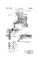
Fig. 1 is a perspective view of an automobile body of the closed type having doors to which the present invention is applicable.
Fig. 2 is a perspective View of a suitable embodiment of a door latch constructed in accordance with the present invention and which is applicable to doors such as shown in Fig. 1 when constructed in accordance with the present invention.
Fig. 3 is a fragmentary perspective view 50 of therear left door of the automobile body Serial No. 83,908.
shown in Fig. 1, illustrating the manner in which it has been formed in accordance with the present invention.
Fig.4 is a fragmentary perspective view corresponding to the view in Fig; 3 but showing the latch of Fig. 2 in assembled relation therewith, the handles for operatingjthe latch being shown in operative relation thereto.
Fig. 5' is a view corresponding to the view of Fig. & but showing the window glass and window glass retaining and guiding channel in assembled relation thereto.
Fig; 6 is a sectional view of Fig. 5 taken in a horizontal plane through the center of the outside latch handle stem.
Fig. 7 is a sectional view of Fig. 5taken in a horizontal plane through the center of the latch bolt. I
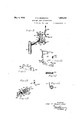
. Fig. 8 is a fragmentary perspective view of the door and its'co-operating pillar post,
the latter being turned out of its true relation with the door in order to bring out more clearly'the depression formed therein for receiving the outwardly projecting handle stem receiving-pocket on the door edge.
Fig. 9 is a perspective view of the latch bolt, roll-back cam and outside operating handle, insideoperating lever, and locking dog and handle, all in operative relationship with each other, to more clearly show the re lation they normally bear to each other.
Fig. 10- is a perspective'view'ofthelatch plate.
Fig. 11 is'a plate cover. H p Fig. 12 is aview of the latch bolt projectmg spring.
Fig. 13 is a perspective view of the locking dog spring.
Fig. 14 is a perspective view of the inside operating handle return and anti-rattle spring.
Fig. 15 is a perspective view taken from the latch plate side of the latch plate cover showing the relation of the locking dog and the locking'dog spring to each other'and to the latch plate cover.
The door latch, as shown in the several views, is built up on the latch plate 25 shown alone in perspective in Fig. 10. 'The plate perspective view of the latch 25 is provided with an outer or forward edge flange provided with a bolt receiving opening 27, and an inner or rear edge flange 28 provided with an opening 29 for receiving the guiding tail of the latch bolt. It is also provided with an extending portion 30, which projects out past the outer flange 26 which define the normally forward face of the latch, and is formed to present a bossed opening 31. Other openings and up-struck tongues are also provided for purposes which will be described later.
The latch bolt 32, shown best in Fig. 9, comprises a. hardened head portion 33 secured to a stamped metal body 34 by rivets such as 35. The body 34 is provided with a downwardly extending portion 36 adjacent its outer or head end, an extending tail portion 37, and an inturned finger portion 38. The head 33 is received and guided in the opening 27 in the flange 26, and the tail portion 37 is received and guided in the opening 29 in the flange 28. A coil spring 39, shown alone in Fig. 12, encircles the tail portion 37 and is held under compression between the fiange 28 and finger 38, thus exerting a constant tendency to project the bolt 32 into locked position.
Adjacent the lower edge of the plate 25 is what I prefer to call the cover plate 40, which is secured in spaced relation to the plate 25 by means of inturned projections or fingers 41, 42 and 43 (see Figures 11 and 15) the ends of which pass into the openings 44, 45, and 46 in the lock plate 25 and are either welded in that position or else their ends may be bent over the opposite face of the plate 25, the similar shorter projections 47 and 48 abutting against the face of the plate 25 to aid in holding the cover 40 in proper spaced relation thereto, and for other purposes which will be described later. The cover plate 40 is provided with an extending end 49 having an opening 50 in alignment with the opening 31 of the plate 25, and between the plate 25 and cover 40 is positioned the roll-back cam 51 whose hub is rotatably received in the openings 31 and 50 and whose cam arm 52 normally abuts against the forward edge of the downwardly projecting portion 36 on the body portion 34 of the bolt 32.
Positioned rearwardly of the roll-back cam 51 is the inside operating lever 53, the lower end of which is received between the cover 40 and plate 25 and is pivotally supported on the pin 54 which passes through and is secured to both the cover 40 and plate 25. The lever 53 extends upwardly from the pin 54 and normally lies immediately adjacent the forward edge of the finger 38 of the latch bolt 32. ,A spiral spring 55 (see Fig. 14) is also provided between the plate 25 and cover 40 rearwardly of the lever 53, its inner end being supported by and being prevented from turning by the two upstanding cars 56 (see Fig. 10) struck out from the plate 25, and its upwardly extending outer end 57 bears against the lever 53 and exerts a constant tendency thereon to swing it forwardly against the stop 58 formed by bending over a portion of the upper edge of the plate 25 to intercept the same.
Also positioned between the cover 40 and plate 25 is the locking dog 59 on which is formed the shaft 60 which in turn is rotatably supported in the plate 25 and cover 40, the inner end of the shaft 60 projecting thru the back face of the latch where it is provided with a lever 61 for the purpose of turning the same. The locking dog 59 is provided with a normally upwardly extending arm 62, the upper end of which, when the dog 59 is rotated to move it forwardly, moves into abutting relationship with the under face of the projection 63 formed on the rear edge of the roll-back cam arm 52, and thus blocks the roll-back cam 51 against rotation. A strip spring 64 (see Fig. 13) is positioned between the cover 40 and plate 25 with its upper end held between the fingers 41 and 47 and its lower end being held in a cut in the projection 48, and is provided with a protruding bend 65. The dog 59 is provided with a projection 66 which, when the dog is in normal or unlocked position, rests against the lower side of the bend 65. When the dog 59 is turned to locked position so that the arm 62 blocks the cam arm 52, the projection 66 is forced past the bend 65, the spring 64 giving to allow such movement, and comes to rest against the upper face of the bend 65, the spring 64, by this means, resiliently holding the dog 59 in either locked or unlocked position. The rela- I tive positions of the spring 64 and dog 59 when the dog is in unlocked position is clearly shown in Fig. 15.
An outside handle 67 provided with a stem 68, the squared end of which is received in the square opening 69 of the roll-back cam 51, is provided for operating the cam 51, and an ornamental handle such as 70 is provided for the upper end of the lever 53.
The operation of the latch, which may be more easily described by reference to Fig. 9 in which is shown only the operating parts thereof is as follows. When the outside handle 67 is turned in a clockwise direction, the roll-back cam 51 is rotated, swinging the up per end of the cam arm 52 rearwardly or to the right, and because it abuts against the downwardly extending portion 36 of the bolt 32 it causes the bolt 32 to be retracted. Vhen the pressure on the handle is released the spring 39 (see sheets one and two) causes the parts to return to normal or latched position. If the upper end of the lever 53 is moved rearwardly or to the right, it draws the bolt 32 after it by reason of the finger 38 engaging its rear edge, and upon release of the pressure on the lever the spring 39 causes the parts to resume their normal position as before. It will be noted that when either the handle 67,01 the lever 53 is employed to retract the bolt 32, the other member remains in its normal position. If it is desired to lock the handle 67 against movement, the free end of the lever 61 is moved upwardly, throwing the arm 62 on the locking dog 59 forwardly to a position under the projection 63 on the roll back cam arm 51 and thereby prevents movement of the arm 51 and handle 67. It will be noted that when the handle 67 is thus locked against movement, the door in which it is assembled may be slammed shut without damage to the mechanism as such locked condition of the handle 67 does not interfere .with the independent retraction of the bolt 32.
The latch as described with the locking dog 59 is adaptable for use on all the doors of a closed vehicle except one, and in that one the dog 59 is omitted and a key operated locking device of any conventional construction, such as those embodied in the outside handle itself, operable from the outside of the door, is incorporated.
As stated above, one of the principal ob jects of the present invention is to provide such latch that may be employed with particular advantage in doors constructed by sheet metal and provided with slidable glass windows, the construction of the latch being such as to permit the window frame side members to be reduced to the minimum width thereby to afford a greater range of vision from within the vehicle body. In order to realize this advantage it is necessary that the edge of the window glass be extended as near as possible to the edge of the door, and to provide means whereby the latch and its inside and outside operating mechanism will not obstruct the free up and down movement of the glass. Accordingly, the door shown in the accompanying drawings is constructed with this in View, and the particular construction for adapting it to receive the latch is a part of the present invention. As shown, the door comprises a sheet metal panel or face 71 to which a sheet metal edge member 72 is secured. This edge member constitutes the face plate for the lock. The member 72 is formed to provide a step 7 3 whereby to provide a rabbeted door edge, and is further provided with an outwardly extending edge 74 over which the marginal edge of the panel- 71 is bent and welded. The rear edge of the member 72 is bent inwardly parallel to the panel 71 to provide an attaching and strengthening flange 75 (see Fig. 7). Supported by the flange 75 and extending transversely across the rear face of the door is what is commonly known as the lock board 76. The latch assembly previously described is secured to the lock board 76, with the forward flange 26 of theplate 25 abutting against the inner face of the door edge member72, by rivets such as 77 the member 72 being provided with an opening 78 for receiving the end of the bolts 32. As previously noted, the y flange 26 constitutes the normally forward edge of the latch, and the extended roll- back cam portions 30 and 49 of the plate 25 and cover 40, respectively, project forwardly of the flange 26, the amount which this extends beyond the flange 26 being sufficient to bring the inner surface of the stem 68 of the handle 67 substantially in line with or forwardly of the forward face of the flange 26, the stem 68 is turned off round between its ends to aid this 1 from the inside of the member 72, in the mem ber 72 at a proper point to receive the extending portion 30 and 49 and the stem 68 of the handle 67. The pocket 7 8 as viewed from the outside face of the member72, of course presents a protuberance as indicated at 80 in Fig. 8. In order to accommodate this protuberance 80' the pillar post 81 must be provided with'a recess 82 as shown in Fig. 8, the post 81 in that figure being turned out of its true relation with the door to better illustrate the same. The pocket 79 in the member 72 in the drawings as shown as having been punched in the metal of the member 72 itself, but it will be evident that it may also be formed by merely cutting out an opening in the member 72 at that point and, if deemed advisable, cover it with a cap or othercover to present the same effect.
As assembled, then, the inner main face of the member 72 presents an unobstructed surface from top to bottom except right at the latch itself which is positioned to one side thereof, and because of its fiat or thin construction it leaves a substantial amount of room, as particularly well shown in Figures 6 and 7, for the passage of the window glass 83 between it and the panel 71. The window glass 83 is supported and guided by the channels 84 which are secured directly against the inner face of the main face portion of the member 72, and, as shown in Fig. 6, the stem 68 of the handle 67 is set far enough forward of the inner face of the main face portion of the member 7 2, in the pocket 79, to allow the channel 84 to clear the same.
' It will be apparent from the foregoing that a construction has been provided whereby the window glass may. be extended to the minimum distance from the outside edge of the.
door, and that'a door latch has been provided which allows such a construction and yet is operable from both sides of the door with equal ease and by an extremely simple con,- struction.-
Formal changes may be made in the specific embodiment of the invention described without departing from the spirit and substance of the broad invention, the scope of which is commensurate with the appended claims.
Having thus described the invention, what I claim is 1. ;A latch comprising a plate provided with a bolt receiving and guiding flange at the forward edge thereof, a latch bolt slid ably received by said flan e, means operable from one'side of said latch for retracting said bolt, means operable from the other side of said latch for retracting said bolt, said last named means comprising a roll-back in dependently supported by an extension of said plate projecting forwardly of said flange, and a roll-back operating means positioned forwardly of said flange.
2. In combination with a door having a face panel, a lock board, and a sheet metal edge member joining the same, a latch secure-d to said lock board provided with a forward ed e flan e in abuttin relation with said edge member, a stem operated roll-back supported forwardly of said flange, and means for housing said roll-back and stem forwardly of the normally rear face of said member whereby a window glass may be slidable up and down between said latch and said panel with its forward edge in substantially abutting relation with the rear face of said edge member.
3. A latch mechanism comprising a horizontally movable belt, a plate for supporting said bolt, a swinging lever for retracting said bolt, a sheet metal housing secured to said plate and partially enclosing the latch mechanism, a rotatable spindle provided with a roll-back for retracting the latch bolt from the outside, a dogging device for dogging the outside roll-back, a spring device supported by said housing for maintaining the dogging device in its extreme operative or inoperative position.
l. In a latch mechanism, a sliding bolt, spring means for normally maintaining the bolt in its protracted position means. for retracting the bolt from the inside, means for retracting the bolt from the outside, said last named means comprising a roll-back, a housing for said roll-back, said housing provided with integral inwardly bent fingers, a spring device received between said fingers and provided with a projection intermediate its ends, a dogging device for engaging the roll-back, said dogging device being snapped into its operative or inoperative position by the proj ecting portion of said sprin 5. In combination with a door provided with a sheet metal edge member having a pocket integrally formed therein, a lock board secured to said edge member, a latch plate mounted on said lock board, a latch bolt provided with an abutment and having an end extending through said edge member slidably mounted on said latch plate, a handle operable from the inside of said door for operating said bolt, and means to operate said bolt exteriorly of said door comprising a handle, a rotatable shaft within said pocket having its inner edge substantially flush with the inner face of said edge member connected at one end to said handle, and a roll-back mounted on said rotatable shaft adapted to engage said abutment.
6. In combination with a door having a sheet metal edge member, a latch having a forwardly positioned flange abutting against said edge member, said latch being provided with a projecting portion extending forwardly of said flange and supporting a roll-back, means for operating said roll-back, and means integral with the edge of said door for housing said forwardly projecting portion, roll-back and operating means therefor.
Signed by me at Detroit, Michigan, U. S. A, this 21st day of January, 1926.
PAUL E. BRENEMAN.
Priority Applications (1)
| Application Number | Priority Date | Filing Date | Title |
|---|---|---|---|
| US83908A US1856689A (en) | 1926-01-26 | 1926-01-26 | Door and latch construction |
Applications Claiming Priority (1)
| Application Number | Priority Date | Filing Date | Title |
|---|---|---|---|
| US83908A US1856689A (en) | 1926-01-26 | 1926-01-26 | Door and latch construction |
Publications (1)
| Publication Number | Publication Date |
|---|---|
| US1856689A true US1856689A (en) | 1932-05-03 |
Family
ID=22181429
Family Applications (1)
| Application Number | Title | Priority Date | Filing Date |
|---|---|---|---|
| US83908A Expired - Lifetime US1856689A (en) | 1926-01-26 | 1926-01-26 | Door and latch construction |
Country Status (1)
| Country | Link |
|---|---|
| US (1) | US1856689A (en) |
-
1926
- 1926-01-26 US US83908A patent/US1856689A/en not_active Expired - Lifetime
Similar Documents
| Publication | Publication Date | Title |
|---|---|---|
| US3767244A (en) | Locks | |
| US3220759A (en) | Latch assembly | |
| US2143965A (en) | Automobile door latch mechanism | |
| US5984384A (en) | Vehicle door latch device with self-cancelling mechanism | |
| US2259670A (en) | Automobile door latch mechanism | |
| US3129026A (en) | Rotary bolt door latch with direct acting detent | |
| US2435987A (en) | Automobile door latch mechanism | |
| US1856689A (en) | Door and latch construction | |
| US3955839A (en) | Door latch | |
| US2546703A (en) | Automobile door lock | |
| US2172169A (en) | Catch and lock mechanism for automobile trunk compartments | |
| US3101604A (en) | Panic-proof door lock | |
| US20130263517A1 (en) | Vehicle door manual lock assembly | |
| US2955865A (en) | Automobile door latch | |
| US2871049A (en) | Rotary gear bolt door latch | |
| US3216756A (en) | Window lock | |
| US4330145A (en) | Double-latch mechanism | |
| US2476332A (en) | Automobile door latch mechanism | |
| US2690347A (en) | Push-pull handle latch | |
| US3385623A (en) | Closure latch | |
| US2476333A (en) | Automobile door latch mechanism | |
| US2162673A (en) | Door latch | |
| US1994134A (en) | Doorlatch | |
| US2796276A (en) | Rotary bolt door latch | |
| US2852296A (en) | Rotary gear bolt door latch |