US1856683A - Truck body - Google Patents
Truck body Download PDFInfo
- Publication number
- US1856683A US1856683A US456163A US45616330A US1856683A US 1856683 A US1856683 A US 1856683A US 456163 A US456163 A US 456163A US 45616330 A US45616330 A US 45616330A US 1856683 A US1856683 A US 1856683A
- Authority
- US
- United States
- Prior art keywords
- posts
- brackets
- frame
- deck
- truck
- Prior art date
- Legal status (The legal status is an assumption and is not a legal conclusion. Google has not performed a legal analysis and makes no representation as to the accuracy of the status listed.)
- Expired - Lifetime
Links
- 238000010276 construction Methods 0.000 description 7
- 238000009408 flooring Methods 0.000 description 2
- 235000000396 iron Nutrition 0.000 description 2
- 239000002184 metal Substances 0.000 description 2
- 229910052751 metal Inorganic materials 0.000 description 2
- 230000000284 resting effect Effects 0.000 description 2
- 229910000746 Structural steel Inorganic materials 0.000 description 1
- 235000013361 beverage Nutrition 0.000 description 1
- 238000009877 rendering Methods 0.000 description 1
- 230000008439 repair process Effects 0.000 description 1
- 238000006467 substitution reaction Methods 0.000 description 1
Images
Classifications
-
- B—PERFORMING OPERATIONS; TRANSPORTING
- B60—VEHICLES IN GENERAL
- B60P—VEHICLES ADAPTED FOR LOAD TRANSPORTATION OR TO TRANSPORT, TO CARRY, OR TO COMPRISE SPECIAL LOADS OR OBJECTS
- B60P3/00—Vehicles adapted to transport, to carry or to comprise special loads or objects
- B60P3/055—Vehicles adapted to transport, to carry or to comprise special loads or objects for transporting bottles
Definitions
- My present invention relates to improvements in truck bodies or frames designed for the use of bottlers for transporting bottled beverages in cases. 7
- the invention aims to provide a simple, economical and durable construction, embodying a plurality of decks, which is of the knockdown character, whereby it will occupy relatively small space when disassembled, thereby effecting economy in freight shipment and otherwise merchandizing the equipment.
- the invention further aims to provide a construction convertible as to number of case supporting decks, whereby the capaclty of the truck may be readily enlarged according to increased demands of a growing business.
- Another object is to provide a construction in which the amount of clearance between decks may be readily changed as desired.
- Still another object is to provide a construction in which repairs can be effected with speed and economy, by reason of the use of readily removable and replaceable parts of a standard and interchangeable nature.
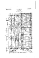
- Figure 1 is a side elevation partly in section.
- Fig. 2 is a section on line 22 of Fig. 1.
- Fig. 3 is a section on line 3-3 of Fig. 1.
- Fig. 4 is a section on line 4-4 of Fig. 1 partly broken away.
- Fig. 5 is a detail view illustrating the sleeves.
- body frame is designed for use upon the ordinary or any desired form of truck chassis, which, as it forms no part of the present invention, is not illustrated herein.
- the body frame selected as an example is 1930. Serial No. 456,163.
- My improved body as herein shown comprises a main frame composed of side sills 1 and cross sills 2. Where wheel pockets are desired, as in the construction shown, the side sills are interrupted at the center of the body to provide space for the wheels, the adjacent ends of the sills being connected by the wheel pocket frames as hereinafter described.
- angle irons 3 having horizontal webs bolted to the side and end frame members and vertical webs 3 extending entirely around the base except at the wheel pockets to serve as a retaining flange to prevent cases from slipping off the body.
- the body is provided with a flooring indicated at 4.
- the wheel pockets are indicated at 5 and are formed of sheet metal having the lower ends of their arched portions secured to the inner ends of the sills 1. Overlying the said arched portions of the wheel pockets are correspondingly curved metal bars 6 having horizontally extending end portions bolted to the sills 1 and overlying webs 3 of the angle irons 3.
- brackets 7 having angle bar portions 7* bolted or otherwise suitably secured to the sills 1 and overlying horizontal webs "3 and also similarly secured to the vertical webs 3 and having also vertical internally threaded openings, to receive vertical posts 8, Y
- additional posts may be provided varying in number in accordance with the length of the body.
- one set of intermediate postsand in order that th'ese may be located midway between the ends of the deck frame is composed of side bars 10 and end bars 10 of angle iron having vertical and inwardly directed horizontal webs, said bars being secured together at the corners by bracket members 11 having angular wings bolted to the ends of said bars and having vertical openings to receive the rods.
- bracket members 11 bolted or otherwise fastened to their outer faces and having vertical passages for the intermediate posts, the central portions of said side frame being supported by short sleeves 9*.
- Said deck frame l10"- is designed to carry a slatted flooring or rack 12 (preferably made in sections) which rests upon the horizontal flanges of the bars 10, within the vertical webs or flanges thereof whereby lateral movement is prevented.
- deck frame may be provided with additional slat supporting means in the shape of frame bar 10.
- the posts are made of such length that, after the first deck frame 1010 is in place, a second setof sleeves 9 is slipped onto the posts and a second deck frame l0 similar to that previously described, is then applied to the posts. If no other decks are desired and this (10*) constitutes the topmost deck, this is secured in place by nuts 12 and achorn lock nuts 13 threaded on the upper ends of the posts.
- the body may be provided with end panels 14 bolted to the vertical flanges of the end bars, and a sign board 15 supported by brackets 16 from the-upper ends of said panel members.
- a truck body of the character described comprising a bed frame, brackets secured to the corners and sides of said bed frame, corner and side posts removably secured at their lower ends to said brackets, lower and upper deck frames having corner and side brackets provided with vertical openings receiving said posts to removably connect the deck frames to said posts, sleeves removably positioned on said posts between the bed frame and lower deck frame brackets and between the lower and upper deck frame brackets in contact with said brackets, and means removably engaged with the upper ends of said posts and contacting with the upper deck frame brackets to hold both deck frames and the sleeves against accidental upward movement on the posts.
- a truck body of the character described comprising a bed frame, brackets secured to the corners and sides of said bed frame, corner "and side posts having their lower ends removably engaged in said brackets, sleeves shorter than said posts and removably positioned thereon with their lower ends resting on said brackets, a deck frame comprising side and end bars, corner brackets connecting said bars, side brackets secured to said side bars, said deck frame brackets having vertical openings receiving said posts to removably connect said deck frame to said posts, said deck frame brackets resting on the upper ends of said sleeves, and means removably secured to said posts and contacting with the upper sides of said deck frame brackets to hold said deck frame and sleeves against accidental upward movement on said posts.
Landscapes
- Engineering & Computer Science (AREA)
- Health & Medical Sciences (AREA)
- Public Health (AREA)
- Transportation (AREA)
- Mechanical Engineering (AREA)
- Floor Finish (AREA)
Description
May 3, 1932.
E. S. ZIEGLER TRUCK BODY Filed May 27, 1930 03 m g} INVENTOR Ed wnfl 221129219 Patented May 3, 1932 STATES UNETE EDWIN S. ZIEGLER, F YORK, PENNSYLVANIA, ASSIGNOR TO YORK-HOOVER BODY COR- .PORATION, OF YORK, PENNSYLVANIA, A CORPORATION OF PENNSYLVANIA TRUCK BODY Application filed May 27,
My present invention relates to improvements in truck bodies or frames designed for the use of bottlers for transporting bottled beverages in cases. 7
The invention aims to provide a simple, economical and durable construction, embodying a plurality of decks, which is of the knockdown character, whereby it will occupy relatively small space when disassembled, thereby effecting economy in freight shipment and otherwise merchandizing the equipment.
The invention further aims to provide a construction convertible as to number of case supporting decks, whereby the capaclty of the truck may be readily enlarged according to increased demands of a growing business.
Another object is to provide a construction in which the amount of clearance between decks may be readily changed as desired. v
Still another object is to provide a construction in which repairs can be effected with speed and economy, by reason of the use of readily removable and replaceable parts of a standard and interchangeable nature.
With these and other objects in view the invention includes the novel features of construction and arrangement and combination of parts hereinafter described, my invention being defined by the claims appended hereto.
An embodiment of the invention is illustrated in the accompanying drawings in which Figure 1 is a side elevation partly in section.
Fig. 2 is a section on line 22 of Fig. 1.
Fig. 3 is a section on line 3-3 of Fig. 1.
Fig. 4 is a section on line 4-4 of Fig. 1 partly broken away.
Fig. 5 is a detail view illustrating the sleeves.
Preliminary to a detailed description of my improved construction I may state that the body frame is designed for use upon the ordinary or any desired form of truck chassis, which, as it forms no part of the present invention, is not illustrated herein. The body frame selected as an example is 1930. Serial No. 456,163.
adapted for use on a truck having relatively high rear wheels, and hence the body is shown with wheel pockets which, of course would be omitted where the truck was of a low wheeled character not rendering these necessary.
My improved body as herein shown comprises a main frame composed of side sills 1 and cross sills 2. Where wheel pockets are desired, as in the construction shown, the side sills are interrupted at the center of the body to provide space for the wheels, the adjacent ends of the sills being connected by the wheel pocket frames as hereinafter described.
To the upper surfaces of the sills are secured angle irons 3 having horizontal webs bolted to the side and end frame members and vertical webs 3 extending entirely around the base except at the wheel pockets to serve as a retaining flange to prevent cases from slipping off the body.
Within the retaining flanges the body is provided with a flooring indicated at 4. The wheel pockets are indicated at 5 and are formed of sheet metal having the lower ends of their arched portions secured to the inner ends of the sills 1. Overlying the said arched portions of the wheel pockets are correspondingly curved metal bars 6 having horizontally extending end portions bolted to the sills 1 and overlying webs 3 of the angle irons 3. I
Art the corners of the body or bed frame are located brackets 7 having angle bar portions 7* bolted or otherwise suitably secured to the sills 1 and overlying horizontal webs "3 and also similarly secured to the vertical webs 3 and having also vertical internally threaded openings, to receive vertical posts 8, Y
the lower ends of which posts are correspondingly threaded and screwed into the threaded openings 7 said posts serving to support upper decks in the manner hereinafter described.
Where the body is of such length as to require it, additional posts may be provided varying in number in accordance with the length of the body. In the form shown in the drawings I have shown one set of intermediate postsand in order that th'ese may be located midway between the ends of the deck frame is composed of side bars 10 and end bars 10 of angle iron having vertical and inwardly directed horizontal webs, said bars being secured together at the corners by bracket members 11 having angular wings bolted to the ends of said bars and having vertical openings to receive the rods.
Midway of the side bars 10 they are provided with bracket members 11 bolted or otherwise fastened to their outer faces and having vertical passages for the intermediate posts, the central portions of said side frame being supported by short sleeves 9*.
Said deck frame l10"- is designed to carry a slatted flooring or rack 12 (preferably made in sections) which rests upon the horizontal flanges of the bars 10, within the vertical webs or flanges thereof whereby lateral movement is prevented.
If desired the deck frame may be provided with additional slat supporting means in the shape of frame bar 10.
Where more than one upper deck is desired the posts are made of such length that, after the first deck frame 1010 is in place, a second setof sleeves 9 is slipped onto the posts and a second deck frame l0 similar to that previously described, is then applied to the posts. If no other decks are desired and this (10*) constitutes the topmost deck, this is secured in place by nuts 12 and achorn lock nuts 13 threaded on the upper ends of the posts. I
If desired the body may be provided with end panels 14 bolted to the vertical flanges of the end bars, and a sign board 15 supported by brackets 16 from the-upper ends of said panel members.
It will be apparent that if a bottler has a plant of small capacity he may provide himself with a truck body having only one deck, for example.
Should subsequent business conditions require, he can enlarge the capacity of the truck by substituting longer posts and using therewithadditional struts and deck or decks.
It will also be obvious that as the parts are all detachable and standardized damage 1 can easily be repaired by mere substitution of parts which are easily p-rocurable.
Having thus described my invention what I claim is:
1. A truck body of the character described comprising a bed frame, brackets secured to the corners and sides of said bed frame, corner and side posts removably secured at their lower ends to said brackets, lower and upper deck frames having corner and side brackets provided with vertical openings receiving said posts to removably connect the deck frames to said posts, sleeves removably positioned on said posts between the bed frame and lower deck frame brackets and between the lower and upper deck frame brackets in contact with said brackets, and means removably engaged with the upper ends of said posts and contacting with the upper deck frame brackets to hold both deck frames and the sleeves against accidental upward movement on the posts.
2. A truck body of the character described comprising a bed frame, brackets secured to the corners and sides of said bed frame, corner "and side posts having their lower ends removably engaged in said brackets, sleeves shorter than said posts and removably positioned thereon with their lower ends resting on said brackets, a deck frame comprising side and end bars, corner brackets connecting said bars, side brackets secured to said side bars, said deck frame brackets having vertical openings receiving said posts to removably connect said deck frame to said posts, said deck frame brackets resting on the upper ends of said sleeves, and means removably secured to said posts and contacting with the upper sides of said deck frame brackets to hold said deck frame and sleeves against accidental upward movement on said posts.
In testimony whereof I affiX my signature.
EDIVIN S. ZIEGLER.
Priority Applications (1)
| Application Number | Priority Date | Filing Date | Title |
|---|---|---|---|
| US456163A US1856683A (en) | 1930-05-27 | 1930-05-27 | Truck body |
Applications Claiming Priority (1)
| Application Number | Priority Date | Filing Date | Title |
|---|---|---|---|
| US456163A US1856683A (en) | 1930-05-27 | 1930-05-27 | Truck body |
Publications (1)
| Publication Number | Publication Date |
|---|---|
| US1856683A true US1856683A (en) | 1932-05-03 |
Family
ID=23811701
Family Applications (1)
| Application Number | Title | Priority Date | Filing Date |
|---|---|---|---|
| US456163A Expired - Lifetime US1856683A (en) | 1930-05-27 | 1930-05-27 | Truck body |
Country Status (1)
| Country | Link |
|---|---|
| US (1) | US1856683A (en) |
Cited By (1)
| Publication number | Priority date | Publication date | Assignee | Title |
|---|---|---|---|---|
| US2567423A (en) * | 1949-07-16 | 1951-09-11 | Andrew C Cleghorn | Powered carrier |
-
1930
- 1930-05-27 US US456163A patent/US1856683A/en not_active Expired - Lifetime
Cited By (1)
| Publication number | Priority date | Publication date | Assignee | Title |
|---|---|---|---|---|
| US2567423A (en) * | 1949-07-16 | 1951-09-11 | Andrew C Cleghorn | Powered carrier |
Similar Documents
| Publication | Publication Date | Title |
|---|---|---|
| US1708588A (en) | Drying rack | |
| US1856683A (en) | Truck body | |
| US2307149A (en) | Platform construction | |
| CA1181783A (en) | Double-decker goods vehicle | |
| US1276556A (en) | Supporting-rack. | |
| US3091195A (en) | Pallet superstructure | |
| US2058891A (en) | Truck equipment for transporting goods containers | |
| US1943023A (en) | Bread rack | |
| US2413404A (en) | Knockdown chassis for trailers | |
| USRE16157E (en) | hinshaw | |
| CN205358936U (en) | Double -layer folding bed | |
| US1957656A (en) | Bread rack | |
| US2325863A (en) | Crate for water bottles or carboys | |
| US1736170A (en) | Portable platform for lift trucks | |
| US1932327A (en) | Truck body | |
| US2343844A (en) | Shipping structure | |
| US1242779A (en) | Portable rack. | |
| US2199737A (en) | Tank mounting | |
| US3541975A (en) | Serving cart | |
| US2205575A (en) | Truck body | |
| US1614412A (en) | Truck body | |
| US1815813A (en) | Metallic truck body | |
| US1366168A (en) | Vehicle-body | |
| US1592134A (en) | Truck body | |
| DE346951C (en) | Railway wagons for the transport of motor vehicles |