US1856682A - Mine timbering apparatus - Google Patents
Mine timbering apparatus Download PDFInfo
- Publication number
- US1856682A US1856682A US546620A US54662031A US1856682A US 1856682 A US1856682 A US 1856682A US 546620 A US546620 A US 546620A US 54662031 A US54662031 A US 54662031A US 1856682 A US1856682 A US 1856682A
- Authority
- US
- United States
- Prior art keywords
- laggings
- cleats
- mine timbering
- post
- timbering
- Prior art date
- Legal status (The legal status is an assumption and is not a legal conclusion. Google has not performed a legal analysis and makes no representation as to the accuracy of the status listed.)
- Expired - Lifetime
Links
- 238000010276 construction Methods 0.000 description 4
- 125000006850 spacer group Chemical group 0.000 description 2
- 230000001419 dependent effect Effects 0.000 description 1
- 238000005065 mining Methods 0.000 description 1
- 230000000284 resting effect Effects 0.000 description 1
- 230000000630 rising effect Effects 0.000 description 1
- 230000003245 working effect Effects 0.000 description 1
Images

Classifications
-
- E—FIXED CONSTRUCTIONS
- E21—EARTH OR ROCK DRILLING; MINING
- E21D—SHAFTS; TUNNELS; GALLERIES; LARGE UNDERGROUND CHAMBERS
- E21D11/00—Lining tunnels, galleries or other underground cavities, e.g. large underground chambers; Linings therefor; Making such linings in situ, e.g. by assembling
- E21D11/02—Lining predominantly with wood
Definitions
- the present invention relates to an apparatus for timbering mines.
- soft or caving ground be supported on the Q sides as well as on the top of the tunnels or horizontal workings and this is done by means of lagging which is placed on the outside of upright posts or timbers. If the ground is caving badly, the posts are often broken or lli forced out of position and have to be replaced,
- the prime object of the present invention is to eliminate the likelihood of the post becoming broken or forced out of position.
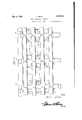
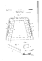
- Figure l is a bottom plan view of an apparatus embodying the features of my invention.
- Figure 2 is a side elevational View thereof.
- Figure 3 is a vertical transverse section therethrough.
- Figure 4 is a perspective view of one of the cleats
- y Figure 5 is a perspective View of one of the laggings.
- each of these cross members 6 denote spaced parallel cross members extending transversely of the mine tunnel, and each of these cross members 6 is provided at its end and in the upper edges thereof with notches 7.
- Posts 8 have their lower ends seated in the notches 7 and extend upwardly, and at their upper ends are seated in corner notches provided in the ends of upper cross members 10.
- serial No. 546,62of y spacedl cleats 11 v that project outwardly a slight distance from the post or uprights dependent upon conditions. The average distance would be about four inches.A
- Extending between, and contacting the outer edges of opposed cleats 11 are'laggings l2, thereby providing adjacent each sidewall 'of the tunnel a plurality of series of relatively spaced laggings '12 interposed between the outer edges of the cleats l1l and an adjacent side wall of the tunnel as shown in Figure 3.
- the laggings l2 of each series are maintained in proper spaced relation through the medium of spacer blocks 13 arranged between the laggings 12 at corre@ sponding ends of the lagging as shown inthe drawings.
- the lowermost laggings l2 may have one edge resting directly on the ground or suitable supporting blocks (not shown).
- a plurality of relatively spaced cross members having notches in their upper end corners, posts having their lower ends seated in said notches and rising from the cross members, upper cross members having notches in their lower end corners to receive the upper ends of the posts, spaced cleats secured to the post and extending outwardly therefrom, and laggings having the inner surfaces thereof iatly contacting the outer ends ofV the cleats, and spacer blocks arranged between vertically alined laggings for retaining the same in relatively spaced relation.
Landscapes
- Engineering & Computer Science (AREA)
- Mining & Mineral Resources (AREA)
- Architecture (AREA)
- Civil Engineering (AREA)
- Structural Engineering (AREA)
- Life Sciences & Earth Sciences (AREA)
- General Life Sciences & Earth Sciences (AREA)
- Geochemistry & Mineralogy (AREA)
- Geology (AREA)
- Supports For Pipes And Cables (AREA)
Description
THUN l v m J-l d- 3 Sheets-Sheet VYIIVH IIIIIII M ZIDRO MINE TIMBERING APPARATUS Filed June 24, 1931 IIIIIIII May3,l932
- Mnl My 3, 1932... M, DDR5 1,856,682
MINE TIMBERING APPARATUS Filed June 24,1931 5 sheets-sheet 2 Inventor May 3, 1932. M. zlDRO MINE TIMBERING APPARATUS 5 Sheets-Sheet Z5 Filed June 24, 1931 Homey Patented May 3, 1932 MATT ZIDRO, OF JEROME, ARIZONA MINE TIMBERING nIBPARAJJJUS` Application led vJune 24,
The present invention relates to an apparatus for timbering mines. As is well known in underground mining it is necessary that soft or caving ground be supported on the Q sides as well as on the top of the tunnels or horizontal workings and this is done by means of lagging which is placed on the outside of upright posts or timbers. If the ground is caving badly, the posts are often broken or lli forced out of position and have to be replaced,
often at frequent intervals.
The prime object of the present invention is to eliminate the likelihood of the post becoming broken or forced out of position..
lll Another very important object of the inventio-n resides in the provision of an apparatus of this nature which is exceedingly simple in its construction, easy to build, thoroughly ef* cient and reliable in use and otherwise Well l adapted to the purpose for which it is designed.
With the above and numerous other objects in view as will appear as the description proceeds, the invention resides in certain novel features of construction, and in the combination and arrangement of parts as will be hereinafter more fully described and claimed.
In the drawings:
Figure l is a bottom plan view of an apparatus embodying the features of my invention.
Figure 2 is a side elevational View thereof.
Figure 3 is a vertical transverse section therethrough.
Figure 4 is a perspective view of one of the cleats, and y Figure 5 is a perspective View of one of the laggings.
Referring to the drawings in detail, it will be seen that the numerals 6 denote spaced parallel cross members extending transversely of the mine tunnel, and each of these cross members 6 is provided at its end and in the upper edges thereof with notches 7. Posts 8 have their lower ends seated in the notches 7 and extend upwardly, and at their upper ends are seated in corner notches provided in the ends of upper cross members 10. To each upright or post 8 there are nailed or otherwise secured thereto a plurality of relatively 1931. serial No. 546,62of y spacedl cleats 11 vthat project outwardly a slight distance from the post or uprights dependent upon conditions. The average distance would be about four inches.A
Extending between, and contacting the outer edges of opposed cleats 11 are'laggings l2, thereby providing adjacent each sidewall 'of the tunnel a plurality of series of relatively spaced laggings '12 interposed between the outer edges of the cleats l1l and an adjacent side wall of the tunnel as shown in Figure 3. The laggings l2 of each series are maintained in proper spaced relation through the medium of spacer blocks 13 arranged between the laggings 12 at corre@ sponding ends of the lagging as shown inthe drawings.
In actual practice, the lowermost laggings l2 may have one edge resting directly on the ground or suitable supporting blocks (not shown).
By the use of this construction, instead of placing the lagging directly on the post it is held away from them by the cleats at right angles to the wall of the tunnel or other 7 working.` These cleats in actual practice are approximately eleven inches in length and should be placed so as to hold the lagging which is placed across the ends of the cleat about four inches away from the post. These dimensions are not of the essence of the invention. If the weight of the ground is then too heavy for the lagging to support, it has quite apparent to those skilled in this art '9 without a more detailed description thereof.'y
The present embodiment of the invention has been described in considerable detail merely for the purposes of exemplification since in actual practice it attains the features 3T' four inches to move, the nails yielding to the y pressure, before positions of the post are en- 8 of advantage enumerated as desirable in the statement of the invention and the above description.
It will be apparent that changes in the details of construction, and in the combination and arrangement of parts may be resorted to without departing from the spirit or scope of the invention as hereinafter claimed or sacrificing any of its advantages.
Having thus described my invention, what I claim as new is:
In an apparatus of the class described, a plurality of relatively spaced cross members having notches in their upper end corners, posts having their lower ends seated in said notches and rising from the cross members, upper cross members having notches in their lower end corners to receive the upper ends of the posts, spaced cleats secured to the post and extending outwardly therefrom, and laggings having the inner surfaces thereof iatly contacting the outer ends ofV the cleats, and spacer blocks arranged between vertically alined laggings for retaining the same in relatively spaced relation.
In testimony whereof I aiix my signature.
MATT ZIDRO.
Priority Applications (1)
| Application Number | Priority Date | Filing Date | Title |
|---|---|---|---|
| US546620A US1856682A (en) | 1931-06-24 | 1931-06-24 | Mine timbering apparatus |
Applications Claiming Priority (1)
| Application Number | Priority Date | Filing Date | Title |
|---|---|---|---|
| US546620A US1856682A (en) | 1931-06-24 | 1931-06-24 | Mine timbering apparatus |
Publications (1)
| Publication Number | Publication Date |
|---|---|
| US1856682A true US1856682A (en) | 1932-05-03 |
Family
ID=24181244
Family Applications (1)
| Application Number | Title | Priority Date | Filing Date |
|---|---|---|---|
| US546620A Expired - Lifetime US1856682A (en) | 1931-06-24 | 1931-06-24 | Mine timbering apparatus |
Country Status (1)
| Country | Link |
|---|---|
| US (1) | US1856682A (en) |
-
1931
- 1931-06-24 US US546620A patent/US1856682A/en not_active Expired - Lifetime
Similar Documents
| Publication | Publication Date | Title |
|---|---|---|
| Atkinson | Neolithic engineering | |
| US3186177A (en) | Safety device for excavations | |
| US1856682A (en) | Mine timbering apparatus | |
| US2000492A (en) | Retaining wall and method of constructing it | |
| US2092511A (en) | Well-rig | |
| US1799160A (en) | Samson post | |
| CN215979428U (en) | Support device for roadway | |
| US1946579A (en) | Process of sinking caissons | |
| US1924511A (en) | Sand box | |
| US269927A (en) | Case fob | |
| US3652058A (en) | Three-position crown block | |
| CN204386609U (en) | Zone of fracture coal face lower end breach supporting facility | |
| US2277701A (en) | Composite wooden flume | |
| CN105758992A (en) | Test bench and method for predicting cavability of top coal | |
| US2135970A (en) | Post hole forming machine | |
| US1583075A (en) | Method and apparatus for supporting timbering in tunnels | |
| RU2425225C1 (en) | Stowing connection strap | |
| US1634104A (en) | Timbering or bracing system | |
| US4249845A (en) | System for reclaiming bulk solids from a storage pile | |
| US1770978A (en) | Mining prop | |
| FR2262176A1 (en) | Modular holiday home construction system - has columns assembled by top and bottom cross-members | |
| US424819A (en) | Means for sinking shafts in soft earth | |
| US61524A (en) | ed gab | |
| US256244A (en) | Waed baumann and william h | |
| SU715808A1 (en) | Partition for closing-off mine workings |