US1856677A - Material handling machine - Google Patents
Material handling machine Download PDFInfo
- Publication number
- US1856677A US1856677A US298285A US29828528A US1856677A US 1856677 A US1856677 A US 1856677A US 298285 A US298285 A US 298285A US 29828528 A US29828528 A US 29828528A US 1856677 A US1856677 A US 1856677A
- Authority
- US
- United States
- Prior art keywords
- conveyor
- frame
- material handling
- handling machine
- cable
- Prior art date
- Legal status (The legal status is an assumption and is not a legal conclusion. Google has not performed a legal analysis and makes no representation as to the accuracy of the status listed.)
- Expired - Lifetime
Links
Images
Classifications
-
- E—FIXED CONSTRUCTIONS
- E21—EARTH DRILLING; MINING
- E21F—SAFETY DEVICES, TRANSPORT, FILLING-UP, RESCUE, VENTILATION, OR DRAINING IN OR OF MINES OR TUNNELS
- E21F13/00—Transport specially adapted to underground conditions
- E21F13/02—Transport of mined mineral in galleries
Definitions
- chine which is adapted to be used within the veins of mines for conveying and loading material on to mine cars, the machine being designed and constructed so that it may be operated with efliciency and moved in cramped and confined quarters.
- a further important object of this invention is to provide a material handling machine of the type described in which the conveyor frame portion is provided with a substantially horizontal loading end to facilitate the placing of material therein.
- a further object of this invention is to provide a material handling-machine having means in connection therewith for illuminating the space around the machine, which is particularly necessary in using the device in mines.
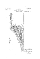
- Fig. 1 is a side view of the material handlingmachine, part being broken away to show the motor and driving means;
- Fig. 2 is a plan view thereof
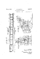
- Fig. 3 is a view of the discharge end of the machine.
- Fig. 4 is an enlarged detail view showing the improved means for adjusting the conveyor on the truck, parts being broken away.
- the numeral 10 designates a conveyor portion which comprises a trough member 11 normally positioned at an incline.
- the said conveyor member and trough have a discharge end 12 and a loading end 13.
- the shape of the conveyor and trough are novel, in View of the fact that the loading end 13 is substantially horizontal. This end may be of any desired length, the main object being to provide a portion of the trough which is substantially parallel to the ground so that material loaded therein will not slide back by the force of gravity.
- From the loading end the conveyor frame and trough incline upwardly, as shown clearly in Fig. 1, to the discharge end where they again extend in a substantially horizontal direction.
- the conveyor frame is provided at its sideportions with outwardly extending and upwardly inclined flanges 14 which are adapted to receive any surplus material which mightbe loaded into the receiving end and direct said material to the trough.
- the conveyor frame and trough are mounted ona truck frame which comprises frame members 15 having bearing portions 16 within which an axle 17 carrying a pairof flanged wheels 18 is journaled.
- Journaled in bearings 27 is a second shaft 28 carrying at its end portions small sprocketwheels 29.
- the said bearings 27 are adjustable by meansof the adjustment member 30 to tighten a pair of spaced-apart-endless chains 31 which pass under the sprocket wheels 28.
- the said endless chains 31 extendfrom the sprocket wheels 28 toward the loading end of the conveyor and pass around sprocket wheels 32 and up over the top of the trough traveling beneath the guiding flange 32 to the discharge end, where they pass around sprocket wheels 33. From there the chains pass through guiding flanges 34 down to and around one side of the sprocket wheels 26, the latter wheels driving the chains.
- a plurality of flight memhers35 Positioned between" the spaced-apart endless chains and" secured at each end thereto are a plurality of flight memhers35 which are adapted to engage material to carry it along the trough.
- brackets Projecting downwardly from side portions of the conveyor frame are brackets; 36- between which a shaft 37 extends. Carried by said shaft is the upper endofajjack izl, said jack having a universal joint connection with said shaft to permit the machine to be jacked up ofi of its wheels with'its lower end resting upon the groundand swung toa desired position when putting it on to or removing it from tracks or for moving it short distances.
- This means comprises a drum 43 which is rotatably mounted on one of the brackets 36, A crank handle 44 is connected with said drum and by turning said handle a rope or cable 45, one end of which isjattached (to the drum 43, may be wound about said drum.
- the said cable 45 passes around apulley 46 rotatably mounted in a block46f which is pivoted to an end of the frame mem-j ber 15. From there the cable passes'around a pulley 47 rotatably mounted in a b'lock47 securedto the lower end of the arm 39; The end of the cable is secured to the upper end of the frame member 15.
- the frame member 15 is L-shaped, its lower end being securedto the end of the motor supporting frame 19.
- the crank handle '44 By turning the crank handle '44 the cable is wound on the drum 43 and the-device may be thus adjusted so that its discharge end is at various distances from the ground.
- the conveyor frame may be maintained in any adjusted position by means of the dog 49 engaging a ratchet 50 in connectiomwith-the drum43.
- 'A hearing 51 connected to the conveyor frame has extending therein an arm 52 having a curved upper end 53. Extending downwardly from the curved upper end is a lamp 54.
- the arm 52 is adjustable in the bearing 51 by means of the set screw 55, so as to vary theheight of the electric lamp.
- the lamp' is covered by a guard 56 to prevent breakage. By means of this lamp the workmen are furnished with the proper light conveniently positioned for their purpose.
- thev conveyor trough may be of any desired width, according to theuse's'to which it is to be put. Furthermore, the length of the substantially horizontal loa dingend 13 may be varied to meet isc eet e ui eme s hen the motor is set] into operation,
- a material handlingmaehine comprising coni eyor,frame having a low; rr eterie e ei ingvi e a d g pperid r har e: 21; m n .i'er o es ater l P- warcl y, asa d. o re er f r ie upport means pivotally connected to the conyeyor frame intermediate itsends a d rum rotatb y oun d o fihe nv iwrfram n arm xte din f m Said. a e t P 1 y otatab me nt d e.
- a material handling machine comprise.
- an inclined conveyor frame having a lower material receiving end and an upper discharge end, means for moving material upwardly on said conveyor frame, supporting means pivotally connected to the conveyor frame intermediate of its ends, an arm extending from said conveyor frame, a pulley rotatably mounted on the lower portion of said arm, a pulley rotatably mounted on a portion of the supporting means, a cable aving one end secured to said supporting means, said cable passingaround the pulley mounted on the lower portion of said arm and around the pulley on the supporting means, and means for exerting a pull on the free end of said cable to cause tilting of the conveyor frame on thesupporting means.
Description
Filed Aug. 8, 1928 2 Sheets-;Sheet ORNEYS May 3, @932- G. R. WHITNALL 1,856,677
MATERIAL HANDLING MACHINE 7 Filed Aug. 8, 1928 2 Sheets-Sheet 2 INVENTOR.
A TTORNEY6 Patented May 3, 1932 uNiTEo STATES PATENT OFFICE GEORGE E. WHITNALL, 0F JANESVILLE, WISCONSIN, ASSIGNOR TO NORTHERN CON- -VEYOR 82; MFG. CO., OF JANESVILLE, WISCONSIN, A CORPORATION OF WISCONSIN MATERIAL HANDLING MACHINE Application filed August 8, 1928. Serial No. 298,285.
. chine which is adapted to be used within the veins of mines for conveying and loading material on to mine cars, the machine being designed and constructed so that it may be operated with efliciency and moved in cramped and confined quarters.
A further important object of this invention is to provide a material handling machine of the type described in which the conveyor frame portion is provided with a substantially horizontal loading end to facilitate the placing of material therein.
It is a further object of this invention to provide a material handling machine having an improved means for adjusting the conveyor on the truck, the said means being adapted to provide leverage for adjusting the height of the discharge end with the minimum amount of effort on the part of the operator.
A further object of this invention is to provide a material handling-machine having means in connection therewith for illuminating the space around the machine, which is particularly necessary in using the device in mines.
It is a further object of this invention to provide a material handling machine which is simple in construction, light in weight, and well adapted for the purpose described.
With the above and other objects in view the invention consists of the improved material handling machine and all its parts and combinations as set forth in the claims and all equivalents thereof.
In the accompanying drawings, in which the same reference characters indicate the same parts in all of the views:
Fig. 1 is a side view of the material handlingmachine, part being broken away to show the motor and driving means;
Fig. 2 is a plan view thereof;
Fig. 3 is a view of the discharge end of the machine; and
Fig. 4: is an enlarged detail view showing the improved means for adjusting the conveyor on the truck, parts being broken away.
Referring to the drawings, the numeral 10 designates a conveyor portion which comprises a trough member 11 normally positioned at an incline. The said conveyor member and trough have a discharge end 12 and a loading end 13. The shape of the conveyor and trough are novel, in View of the fact that the loading end 13 is substantially horizontal. This end may be of any desired length, the main object being to provide a portion of the trough which is substantially parallel to the ground so that material loaded therein will not slide back by the force of gravity. From the loading end the conveyor frame and trough incline upwardly, as shown clearly in Fig. 1, to the discharge end where they again extend in a substantially horizontal direction. The conveyor frame is provided at its sideportions with outwardly extending and upwardly inclined flanges 14 which are adapted to receive any surplus material which mightbe loaded into the receiving end and direct said material to the trough.
f The conveyor frame and trough are mounted ona truck frame which comprises frame members 15 having bearing portions 16 within which an axle 17 carrying a pairof flanged wheels 18 is journaled. A motor supportingsprocket wheels 26. Journaled in bearings 27 is a second shaft 28 carrying at its end portions small sprocketwheels 29. The said bearings 27 are adjustable by meansof the adjustment member 30 to tighten a pair of spaced-apart-endless chains 31 which pass under the sprocket wheels 28.
- The said endless chains 31 extendfrom the sprocket wheels 28 toward the loading end of the conveyor and pass around sprocket wheels 32 and up over the top of the trough traveling beneath the guiding flange 32 to the discharge end, where they pass around sprocket wheels 33. From there the chains pass through guiding flanges 34 down to and around one side of the sprocket wheels 26, the latter wheels driving the chains.
Positioned between" the spaced-apart endless chains and" secured at each end thereto are a plurality of flight memhers35 which are adapted to engage material to carry it along the trough.
Projecting downwardly from side portions of the conveyor frame are brackets; 36- between which a shaft 37 extends. Carried by said shaft is the upper endofajjack izl, said jack having a universal joint connection with said shaft to permit the machine to be jacked up ofi of its wheels with'its lower end resting upon the groundand swung toa desired position when putting it on to or removing it from tracks or for moving it short distances.
Projecting from a medial portion of the conveyor frame is a pair of arms .39 between the lower ends of which a shaft 40 extends, Rotatably mounted on the shaft is a cable reel 41, A cable 42 is wound on the reel, one end of the cable being in connection with the electric motor 20 and the other end being connected to a distant source of -electric power (not shown).
An important feature ofthe device resides in the means for tilting the conveyor frame on the truck. This means comprises a drum 43 which is rotatably mounted on one of the brackets 36, A crank handle 44 is connected with said drum and by turning said handle a rope or cable 45, one end of which isjattached (to the drum 43, may be wound about said drum. The said cable 45passes around apulley 46 rotatably mounted in a block46f which is pivoted to an end of the frame mem-j ber 15. From there the cable passes'around a pulley 47 rotatably mounted in a b'lock47 securedto the lower end of the arm 39; The end of the cable is secured to the upper end of the frame member 15. The frame member 15 is L-shaped, its lower end being securedto the end of the motor supporting frame 19. By turning the crank handle '44 the cable is wound on the drum 43 and the-device may be thus adjusted so that its discharge end is at various distances from the ground. By providing the drum 43 and the pulleys 46 and 47,,a powerful leverage is obtained which permits raising and lowering the conveyor frame with the minimum amount .of effort. The conveyor frame may be maintained in any adjusted position by means of the dog 49 engaging a ratchet 50 in connectiomwith-the drum43.
'A hearing 51 connected to the conveyor frame has extending therein an arm 52 having a curved upper end 53. Extending downwardly from the curved upper end is a lamp 54. The arm 52 is adjustable in the bearing 51 by means of the set screw 55, so as to vary theheight of the electric lamp. The lamp'is covered by a guard 56 to prevent breakage. By means of this lamp the workmen are furnished with the proper light conveniently positioned for their purpose.
It to be'under'stood that'thev conveyor trough may be of any desired width, according to theuse's'to which it is to be put. Furthermore, the length of the substantially horizontal loa dingend 13 may be varied to meet isc eet e ui eme s hen the motor is set] into operation,
hreugh the abov sc ibed. dr i g mea the endless chains are driven andanate rial which, is loaded into the horizontallower end is upwardly, along the trough the lig ts, 3 t s h e re 'i e pp r outerend portion into carsoig other'recep tacles. The substantially horizontal lower; end greatly facilitates loading" of, iiiaterialf'in to the conveyor, 21$; efore pointedout. When it is desired to vary the height of the dis charge end for cars of: different heights this may be readily accomplished through the novel adjJSt iIent; means above described.
i All structural members of the machine, and all plates and sheets are ,cpastmeta p erer ably of aluminum to render the device: light in weight so y it be handled' m'ore easily thelcramped passageways of min'es.
E-rom the foregoing description it, will "be seen thatfthe improved material handling machine is simple in; construction, strongfiand durable, and well adapted forthapurp ose deri ed; My A "What I claim is:
1.. A material handlingmaehine, comprising coni eyor,frame having a low; rr eterie e ei ingvi e a d g pperid r har e: 21; m n .i'er o es ater l P- warcl y, asa d. o re er f r ie upport means pivotally connected to the conyeyor frame intermediate itsends a d rum rotatb y oun d o fihe nv iwrfram n arm xte din f m Said. a e t P 1 y otatab me nt d e. the ev l d said arm a; pulleyblock pivoted to, aporon f t es ppo i emeee a Pu ey r e? ably carried by said pulleyblock; a eable hay ingone end securedto saidsupporting said cable passing around thepulley. mount} ed on the lower end of; said arm, around the pulley connected ;to the supporting means, and to said drum, thev conveyor. frame being adjustably tiltableonthe supporting means to vary the height of thedischarge end o f the. conveyor v frame ,7 by the rotation of said drum; and means for maintainingflsziidconveyor frame in any adjusted position; l
2. A material handling machine comprise.
ing an inclined conveyor frame having a lower material receiving end and an upper discharge end, means for moving material upwardly on said conveyor frame, supporting means pivotally connected to the conveyor frame intermediate of its ends, an arm extending from said conveyor frame, a pulley rotatably mounted on the lower portion of said arm, a pulley rotatably mounted on a portion of the supporting means, a cable aving one end secured to said supporting means, said cable passingaround the pulley mounted on the lower portion of said arm and around the pulley on the supporting means, and means for exerting a pull on the free end of said cable to cause tilting of the conveyor frame on thesupporting means.
In testimony whereof, I afiix my signature.
GEORGE R. WHITNALL.
Priority Applications (1)
| Application Number | Priority Date | Filing Date | Title |
|---|---|---|---|
| US298285A US1856677A (en) | 1928-08-08 | 1928-08-08 | Material handling machine |
Applications Claiming Priority (1)
| Application Number | Priority Date | Filing Date | Title |
|---|---|---|---|
| US298285A US1856677A (en) | 1928-08-08 | 1928-08-08 | Material handling machine |
Publications (1)
| Publication Number | Publication Date |
|---|---|
| US1856677A true US1856677A (en) | 1932-05-03 |
Family
ID=23149847
Family Applications (1)
| Application Number | Title | Priority Date | Filing Date |
|---|---|---|---|
| US298285A Expired - Lifetime US1856677A (en) | 1928-08-08 | 1928-08-08 | Material handling machine |
Country Status (1)
| Country | Link |
|---|---|
| US (1) | US1856677A (en) |
Cited By (1)
| Publication number | Priority date | Publication date | Assignee | Title |
|---|---|---|---|---|
| US2541462A (en) * | 1945-07-27 | 1951-02-13 | Jake C Cooley | Mobile conveyer |
-
1928
- 1928-08-08 US US298285A patent/US1856677A/en not_active Expired - Lifetime
Cited By (1)
| Publication number | Priority date | Publication date | Assignee | Title |
|---|---|---|---|---|
| US2541462A (en) * | 1945-07-27 | 1951-02-13 | Jake C Cooley | Mobile conveyer |
Similar Documents
| Publication | Publication Date | Title |
|---|---|---|
| US1989537A (en) | Conveyer | |
| US2760622A (en) | Universal elevator | |
| US4765461A (en) | Mobile elevator conveyor | |
| US1856677A (en) | Material handling machine | |
| US1989502A (en) | Conveyer belt unloader | |
| US2368414A (en) | Inclined elevator | |
| US1114425A (en) | Elevator. | |
| US2212702A (en) | Case stacker | |
| US1582411A (en) | Method of and apparatus for working mines | |
| US2746592A (en) | Power operated loader | |
| US3037612A (en) | Portable elevator | |
| US1950506A (en) | Portable adjustable grain elevator | |
| US1117619A (en) | Elevator. | |
| US1855257A (en) | Portable box car loader | |
| US2709514A (en) | Conveyors for sand, gravel, and the like | |
| US1527486A (en) | Loader and unloader eor railroad cars | |
| US1332292A (en) | Cane-shifting apparatus | |
| US977518A (en) | Elevator. | |
| US2644570A (en) | Material elevator | |
| US1613923A (en) | Loading machine | |
| US1027669A (en) | Car-unloader. | |
| US2984333A (en) | Conveying mechanism | |
| US2071743A (en) | Beet piling machine | |
| US1017094A (en) | Manure-loader. | |
| US1720843A (en) | Conveying apparatus |